Transcription
DESIGN GUIDE MD #1Roof Gutter Design MethodCONSTRUCTION DETAILSAND SPECIFICATIONSMarylandRevised – October 2004
TABLE OF CONTENTSSECTIONPAGESIGeneral Information1IIConstruction Specifications and WorksheetsDesign DataConstruction Check DataRoof Gutter Design InstructionsWorksheet 1 (Roof Gutter Design Sheet)Worksheet 2 (Underground Outlet Design Sheet)Chart 1 (5 Minute Rainfall Intensities)Figure 1 (Galvanized K-Style Gutter)Figure 2 (Aluminum K-Style Gutter)Figure 3 (Schedule 40 Half-Round)Figure 4 (Downspout Outlet Sizing)Figure 5 (Corrugated Underground Outlet Drain Chart)Figure 6 (Smooth Underground Outlet Drain Chart)Figure 7 (Fascia Boards Replacement Flow Chart)234567891011121314IIIConstruction Specifications15IVConstruction DrawingsDetails:558-A Detail of leader pipe and downspout with underground outlet558-B Detail of leader pipe and downspout with splash pad558-C 6” half round PVC gutter hanger558-D 6” half round PVC gutter558-E 8” half round PVC gutter558-F 8” half round PVC gutter hanger16-21Sizing ExampleWorksheet 1Worksheet 2 Underground Outlet sizing23-252425VDesign Guide MD#1 Roof Gutter Design MethodNRCS Engineering, MarylandOctober 2004Page i171819202122
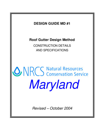
SECTION IGENERALThis design guide is a technical resource prepared by the Maryland NRCS Engineering staffand is intended for use by the NRCS in Maryland and its partners. Construction drawings for someof the gutter options are included, as well as other appropriate construction details andspecifications.To aid in the design process, some drawings and specifications are available online at theMaryland NRCS website at www.md.nrcs.usda.gov. No changes are allowed on these detailswithout prior approval from the NRCS engineering staff.There are many different manufactures of roof gutter and related materials. The flows andcapacities of the roof gutter and downspouts shown in this design guide are based on actualmeasurements taken from some of the materials available. For practical purposes the roof gutterdepths and areas used are assumed to hold true for all available gutter of a given style, top widthand material even though differences do occur. It is the judgement of the engineering staff that thesedifferences are minor and are neglected in the development of this design guide. The capacities ofdownspout outlets are based on using the manufacturers preformed (insert) outlets.Not all sizes of downspouts will fit on a given size of roof gutter. Typically, a 5-inch top widthK-style gutter can receive a 2” x 3” downspout. A 3” x 4” downspout can also fit. Some trimming ofthe flange on the preformed outlet may be required. A 6-inch top width K-style gutter can receive a3’ x 4” downspout. A 4” x 5” downspout can also fit, but again some trimming of the flange of thepreformed downspout outlet may be required. The above sizing is reflected in the development ofFigure 4 (Downspout Outlet Sizing, Leader Pipe Sizing). The use of 4” x 5” downspout outletsstarts at a depth of gutter of 4.5 inches. This corresponds to a minimum top width of 6 inches. Theavailability of 7-inch top width K-style gutter has been poor in the past. However, in recent yearssome seamless forms of 7-inch gutter as well as other sizes have become available. Sizes largerthan 7 inches have also been developed. Check for local availability before specifying sizes 7inches or larger.In section II, Construction Check Data are contractor certification statements. Contractorcertification is highly encouraged. Many roof runoff systems are constructed on buildings requiringa ladder or hydraulic lift in order to properly inspect the work being completed. In addition, the typeof hangers used and materials available is constantly changing. In lieu of climbing ladders andusing the hydraulic lifts to inspect the installed work, the contractor certifications are recommended.The use of snow guards is not mentioned and their use is neither encouraged nordiscouraged. Some of the buildings in which roof gutters are being installed are over a century old.Even though the condition of these buildings may be good, we feel it inappropriate to add anyloading to the roofs. The decision for the use of snow guards is that of the landowners.Rafters and fascia boards must be in good conditions in order to properly hang and supportthe roof gutter. It is common for rafter ends to be damaged and fascia boards to be missing ordamaged. Rafter ends must be repaired and fascia boards replaced as needed. When roofs arein poor conditions repairs should be made by the landowner before any recommendations to installroof gutter are made. There may be situations when a roof is in a poor or unsafe condition andalternatives other than roof runoff structure will be required. See Figure 7 for a flow chart indetermining fascia board replacement.Design Guide MD#1 Roof Gutter Design MethodNRCS Engineering, MarylandOctober 2004Page 1
In section IV of the design guide is a sample design, which includes design calculations andplan sketch.SECTION IIDESIGN DATARecord on appropriate engineering paper. The following is a list of the minimum required designdata:1.Determine roofs, which need roof runoff structure and where the systems may safely outlet.2.Determine peak runoff from each roof for the design storm selected.3.Select type of gutter to be used.4.Size gutter based on type, peak flow and slope. (See Figures 1,2 and 3).5.Determine the downspout outlets required for each roof to be guttered, and choose adownspout system. (See Figure 4).6.Drawings shall include the following as a minimum: Plan view; gutter location, gage, type,size, direction, slope, fascia board and rafter end replacement or repair, and mountinginstructions, underground outlet type, size, direction and installation instructions, andconstruction specifications.Design Guide MD#1 Roof Gutter Design MethodNRCS Engineering, MarylandOctober 2004Page 2
CONSTRUCTION CHECK DATARecord on appropriate engineering paper.construction check data:The following is a list of the minimum required1.Documentation of site visits on CPA-6. The documentation shall include the date, whoperformed the inspection, specifics as to what was inspected, all alternatives discussed,and decisions made and by whom.2.Contractor certification – certifying the roof gutter and downspout type, sizes, gage, roofgutter slope and mounting method.If rafter ends or fascia boards are repaired or replaced, the certification shall also include therafter end and fascia board material size, type and mounting method.I certify that the roof gutter and downspout type, size, gage, roof gutter slope and mountingmethod are as shown on the plans and specifications.(contractor)(date)I certify that the roof gutter and downspout type, size, gage, roof gutter slope and mountingmethod are as shown on the plans and specifications. Rafter ends and/or fascia boardshave been repaired or replaced as follows:(Contractor)(Date)3.Verify the roof gutter, size and gage, downspout opening size, downspout size, length andlocation.4.When applicable, verify the underground outlet size, type, location, outlet type, rodent guardtype, vertical distance between invert of outlet pipe and normal water in outlet stream or ditchand vertical distance between invert of outlet pipe and top of bank.5.Sign and date final notes and plans and include statement that practice meets or exceedsplans and NRCS practice standard.Design Guide MD#1 Roof Gutter Design MethodNRCS Engineering, MarylandOctober 2004Page 3
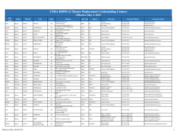
ROOF GUTTER DESIGN INSTRUCTIONS1.Choose the 10-year frequency 5 minute rainfall (see Chart 1). Record this on line 1 ofworksheet 1. For animal waste management use the 25-year frequency 5-minute rainfall.2.Label roof or roof segments and calculate roof area. Record this on line 2.3.Multiply roof area (sq.ft.) by rainfall intensity (ft./sec.) to obtain peak flow (cfs). Place on line2 of worksheet.4.Choose a roof gutter type, size and slope from Figures 1, 2 or 3 to carry the desired peakflow for each roof segment. If a reasonable size and slope do not exist, break the roof intosmaller segments and repeat. Record this on line 3 of worksheet.Make sure the type selected is readily available locally.During the design procedure, when possible, attempt to keep the roof gutter size and slopeuniform. This will help to minimize confusion during installation.Keep in mind that the slope and length of the gutter, width of fascia board and roofing slopeand overhang are critical to make sure that snow will not hang up on gutter and that roofrunoff will not overshoot the gutter. Steep roof gutter slopes should be reserved for shortruns only.5.Sizing the gutter outlet is a two-stage operation. The first step consists of choosing thedownspout outlets required for the given peak flow. The second step consists of choosing aleader pipe for the peak flow or combination of peak flows.Keep in mind the following when sizing downspout outlets for different sizes of roof gutter.Typically, a 5-inch top width K-style gutter can receive a 2” x 3” downspout. A 3” x 4”downspout can also fit. Some trimming of the flange on the preformed outlet may berequired. A 6-inch top width K-style gutter can receive a 3’ x 4” downspout. A 4” x 5”downspout can also fit, but again some trimming of the flange of the preformed downspoutoutlet may be required.a. From Figure 4, using the depth of gutter for the roof gutter size chosen read vertically upto the desired peak flow. Choose any downspout/combination above this level.b. Because of increased head, a combination of downspouts and roof segments may beadded together into one pipe. If the combined peak flow is less than 1.0 cfs, use 4”schedule 40 pipe. If the combined peak flow is between 1.0 and 2.5 cfs use 6” schedule40 pipe. If the combined peak flow is between 2.5 and 4.8 cfs use 8” schedule 40 pipe.Note: Sizing is based on a leader pipe height of 10 feet and a minimum slope of 25percent.6.If the roof runoff system outlets into an underground system, use the underground outlet,design sheet and Figures 5 and 6 to design a gravity flow outlet system. Record this onworksheet 2. Figures 5 and 6 may also be used to size horizontally suspended leaderpipes. These are often used on larger roof runoff systems.Design Guide MD#1 Roof Gutter Design MethodNRCS Engineering, MarylandOctober 2004Page 4
Work Sheet 1 – Roof Gutter DesignCOOPERATOR DATEADDRESS BY1) Ten-year or twenty-five-year frequency five minute rainfall, from Chart 1.(Rainfall intensity ft./sec.)Note: For systems protecting a waste storage structures, use the 25-year frequency.2)Roof AreaXRainfall Intensity Peak FlowRoof # sq.ft.Xft./sec. cfsRoof # sq.ft.Xft./sec. cfsRoof # sq.ft.Xft./sec. cfsRoof # sq.ft.Xft./sec. cfsRoof # sq.ft.Xft./sec. cfsRoof # sq.ft.Xft./sec. cfsRoof # sq.ft.Xft./sec. cfsRoof # sq.ft.Xft./sec. cfs3) Roof Gutter Size (From Figures 1, 2 or 3)(Circle One)Roof # Use ”Top (Aluminum/galvanized) @ ”Pitch in 100 ft.Roof # Use ”Top (Aluminum/galvanized) @ ”Pitch in 100 ft.Roof # Use ”Top (Aluminum/galvanized) @ ”Pitch in 100 ft.Roof # Use ”Top (Aluminum/galvanized) @ ”Pitch in 100 ft.Roof # Use ”Top (Aluminum/galvanized) @ ”Pitch in 100 ft.Roof # Use ”Top (Aluminum/galvanized) @ ”Pitch in 100 ft.Roof # Use ”Top (Aluminum/galvanized) @ ”Pitch in 100 ft.Roof # Use ”Top (Aluminum/galvanized) @ ”Pitch in 100 ft.4) Downspout Opening (orifice) Sizing. (See Figure 4).(combination)Roof # Use - ” X ” Downspout w/ ” LeaderRoof # Use - ” X ” Downspout w/ ” LeaderRoof # Use - ” X ” Downspout w/ ” LeaderRoof # Use - ” X ” Downspout w/ ” LeaderRoof # Use - ” X ” Downspout w/ ” LeaderRoof # Use - ” X ” Downspout w/ ” LeaderRoof # Use - ” X ” Downspout w/ ” LeaderDesign Guide MD#1 Roof Gutter Design MethodNRCS Engineering, MarylandOctober 2004Page 5
Underground Outlet Design Sheet - Worksheet 2LineDesign ReachLengthIndesignreachInput"Q" rade ss:Sta. b Class:Sta.Cooperator:Comments:DESIGN SKETCHDesign Guide MD#1 Roof Gutter Design MethodNRCS Engineering, MarylandOctober 2004Page 6Designed by:Date:Approved by:Date:Certified by:Date:
5 Minute Rainfall Intensities for Ten and Twenty YearFrequency StormsChart 1CountyAlleganyAnne eryPrince George'sQueen Anne'sSomersetSt. Mary'sTalbotWashingtonWicomicoWorchester10 YearFt./Sec.25 .000190.000190.000180.000200.00020Design Guide MD#1 Roof Gutter Design MethodNRCS Engineering, MarylandOctober 2004Page 7
Figure 1 - PEAK FLOW ESTIMATES FOR GALVANIZED K-STYLE ROOF GUTTER5" TOP WIDTH K STYLE GUTTERAREA PITCH IN 100 FT.SLOPE FT/FTQ CFSPITCH IN 100 FT.SLOPE FT/FTQ CFS0.1192sq.ft.WP 1.042ftN 0.0121/2"1"1 1/2"2"2 1/2"3"3 020.3180.3340.3496" TOP WIDTH K STYLE GUTTERAREA PITCH IN 100 FT.SLOPE FT/FTQ CFSPITCH IN 100 FT.SLOPE FT/FTQ CFS0.1671sq.ft.WP 1.204ftN 0.0121/2"1"1 1/2"2"2 1/2"3"3 810.5070.5320.5567" TOP WIDTH K STYLE GUTTERAREA PITCH IN 100 FT.SLOPE FT/FTQ CFSPITCH IN 100 FT.SLOPE FT/FTQ CFS0.2482sq.ft.WP 1.5ftN 0.0121/2"1"1 1/2"2"2 1/2"3"3 040.8470.8890.928NOTE: AREA AND WP ARE BASED ON ARMCO GALVANIZED K STYLE GUTTERDesign Guide MD#1 Roof Gutter Design MethodNRCS Engineering, MarylandOctober 2004Page 8
Figure 2 - PEAK FLOW ESTIMATES FOR ALUMINUM K-STYLE ROOF GUTTER5" TOP WIDTH K STYLE GUTTERAREA PITCH IN 100 FT.SLOPE FT/FTQ CFSPITCH IN 100 FT.SLOPE FT/FTQ CFS0.1042sq.ft.WP 0.9333ftN 0.0121/2"1"1 1/2"2"2 1/2"3"3 600.2740.2870.3006" TOP WIDTH K STYLE GUTTERAREA PITCH IN 100 FT.SLOPE FT/FTQ CFSPITCH IN 100 FT.SLOPE FT/FTQ CFS0.154sq.ft.WP 1.1167ftN 0.0121/2"1"1 1/2"2"2 1/2"3"3 420.4660.4880.5107" TOP WIDTH K STYLE GUTTERAREA PITCH IN 100 FT.SLOPE FT/FTQ CFSPITCH IN 100 FT.SLOPE FT/FTQ CFS0.2278sq.ft.WP 1.3333ftN 0.0121/2"1"1 1/2"2"2 1/2"3"3 540.7940.8330.870NOTE: AREA AND WP ARE BASED ON ALCOA AND ARMCO ALUMINUM K STYLE GUTTERDesign Guide MD#1 Roof Gutter Design MethodNRCS Engineering, MarylandOctober 2004Page 9
Figure 3 - PEAK FLOW ESTIMATES FOR SCHEDULE 40 1/2 ROUND ROOF GUTTER4" TOP WIDTH 1/2 ROUND GUTTERAREA PITCH IN 100 FT.SLOPE FT/FTQ CFSPITCH IN 100 FT.SLOPE FT/FTQ CFS0.044sq.ft.WP 0.524ftN 0.0111/2"1"1 1/2"2"2 1/2"3"3 990.1040.1090.1146" TOP WIDTH 1/2 ROUND GUTTERAREA PITCH IN 100 FT.SLOPE FT/FTQ CFSPITCH IN 100 FT.SLOPE FT/FTQ CFS0.098sq.ft.WP 0.785ftN 0.0111/2"1"1 1/2"2"2 1/2"3"3 870.3020.3170.3318" TOP WIDTH 1/2 ROUND GUTTERAREA PITCH IN 100 FT.SLOPE FT/FTQ CFSPITCH IN 100 FT.SLOPE FT/FTQ CFS0.175sq.ft.WP 1.05ftN 0.0111/2"1"1 1/2"2"2 1/2"3"3 210.6550.6870.717NOTE: AREA AND WP ARE BASED ON 1/2 OF CIRCULAR SCHEDULE 40 PIPEDesign Guide MD#1 Roof Gutter Design MethodNRCS Engineering, MarylandOctober 2004Page 10
Design Guide MD#1 Roof Gutter Design MethodNRCS Engineering, MarylandOctober 2004Page 1100.10.7PE0.6A QK0.5cF f 0.4L s0.3OW0.20.83.54.555.566.53.50" deep4.50" deep5.50" deep4.75" deep5.25" deep6.50" deepGalvanizedNote: Peak flows are estimatedusing manufacturers preformedoutlets5" top6" top7" topAluminumDOWNSPOUT LEADER SIZINGFrom 0 - 1.0 cfs use a 4” diameter downspout leader pipeFrom 1.0 - 2.5 cfs use a 6” diameter downspout leader pipeFrom 2.5 - 4.8 cfs use a 8” diameter downspout leader pipeDEPTH OF ROOF GUTTER 5Figure 4LEADER PIPE SIZINGDOWNSPOUT OUTLET SIZING
Design Guide MD#1 Roof Gutter Design MethodNRCS Engineering, MarylandOctober 2004Page 12IN0.01DISC1HCAFRSG0.1E100.1V 16”4”1V 2V 5V 3V 6SLOPE IN FEET PER 100 FEET8”MANNING N 0.015CORRUGATED PLASTIC DRAIN TUBINGFIGURE 5UNDERGROUND OUTLET DRAIN CHARTV 410
Design Guide MD#1 Roof Gutter Design MethodNRCS Engineering, MarylandOctober 2004Page 13IN0.01DISC1HCAFRSGE 0.1100.1V 18”6”1V 6V 4SLOPE IN FEET PER 100 FEET4”V 2V 3MANNING N 0.011SMOOTH SURFACE TUBINGFIGURE 6V 5UNDERGROUND OUTLET DRAIN CHART10
Design Guide MD#1 Roof Gutter Design MethodNRCS Engineering, MarylandOctober 2004Page 14ReplacenoPaint, Coverwith Vinyl orAluminumnoFascia BoardsPainted,or CoveredyesyesnoyesFascia Boards& Rafter Endsare in goodconditionyesDo NotReplaceProvide one of the following Decrease support spacing to 12 inches. If rafters are @ 24” spacing or lessinstall supports through fasciainto rafter ends. Use nut and bolts @ 24 inch spacingbetween rafters.noNominalThickness2” or GreaterReplaceand Repairas neededFASCIA BOARD REPLACEMENTFigure 7
SECTION IIICONSTRUCTION SPECIFICATIONS1.All materials and construction shall be in accordance with applicable NRCSstandards and construction specifications.2.All components of the completed system shall conform to the lines, grades,elevations, dimensions and materials shown on the plans.3.Any changes in the plans or specifications must be approved by the original planapprover prior to being made. Changes are to be reviewed by the landowner forconcurrence.4.All disturbed areas shall be fertilized, seeded, and mulched or otherwise stabilized asrequired on the construction plans.5.Existing fascia boards that are damaged, rotten, otherwise unstable or with a nominalthickness less than 2 inches, shall be replaced.6.Rafter ends that are damaged or rotted shall be repaired.7.All lumber used for fascia boards or for rafter end repair shall have a nominalthickness of 2 inches. Cover all fascia boards with aluminum or vinyl flashing or paintbefore the roof gutter is installed.8.Down spout outlet connections shall be the manufacturer’s preformed (insert) outletsfor the given size shown on the design, unless otherwise approved.9.Aluminum gutters and downspouts shall have a minimum thickness of 0.027 inch.10. Galvanized steel gutters and downspouts shall have a minimum thickness of 28 gage.11. Where animals or equipment may come in contact with downspouts, steel pipe,schedule 40 PVC or similar material will be used for the downspout.12. Roof gutter supports shall have a maximum spacing of 24 inches unless otherwiseapproved. Roof gutters shall be mounted to the fascia board using hidden hangers,bolts and ferrules, gutter screws and ferrules, or cradles. Other methods must beapproved by the engineer. Spike and ferrules are not approved.13. Itemized invoices from suppliers shall be provided to verify gutter and downspoutsize, length, material, material gage, and hanger type.14. The Soil Conservation District makes no representation as to the existence ornonexistence of any utilities at the construction site. Shown on these constructiondrawings are those utilities, which have been identified. It is the responsibility of thelandowners or operators and contractors to assure themselves that no hazard existsor damage will occur to utilities. Miss Utility should be contacted at1 800-257-7777.Design Guide MD#1 Roof Gutter Design MethodNRCS Engineering, MarylandOctober 2004Page 15
SECTION IVConstruction DrawingsDesign Guide MD#1 Roof Gutter Design MethodNRCS Engineering, MarylandOctober 2004Page 16
MARYLAND STANDARDS FOR AGRICULTURAL BMPSDETAIL 558-A - ROOF RUNOFF" STYLE GUTTER @FT./FT. OR %GUTTER MATERIAL. NOMINAL THICKNESS (MIN. 0.027")USE HIDDEN HANGERS @ 24" SPACING."x" FASCIA(SEE NOTE )DOWNSPOUT," DIAM. OR"xNOMINAL THICKNESS" (SEE SHEET(MINIMUM NOMINAL THICKNESS 0.027 IN)"FOR GUTTER LOCATION)INSERT DOWNSPOUTIN RISER 6" MIN.FT.(10 FT. MIN)DOWNSPOUT HANGERS(SPACING @ 10' O.C. MAX.)EXISTING GROUNDFT.(2 FT. MIN)RISER UNIT " DIA.SCH 40 PVC (NON-PERFORATED)WITH 90 ELBOWSLOPE%OUTLET SECTION" DIA. SOLID SCH 40 PVC(LAST 10' SECTION)INSTALL A FLAP ORFORK TYPE SELFSELF CLEANING(OR EQUIVALENT)ANIMAL GUARDELEV.FT.ELEV.(AS NEEDED)CORRUGATED PLASTIC TUBING" DIAM.,MEETING THE REQUIREMENTS OF ASTM F 405,HEAVY DUTY CPT.NOTE:1) FASCIA BOARD MATERIAL TO BE SPRUCE PINE FIR ORBETTER, COVER WITH ALUMINUM FLASHING ORPAINT PRIOR TO INSTALLATION OF ROOF GUTTER.U.S.DEPARTMENT OF AGRICULTURENATURAL RESOURCES CONSERVATION SERVICEDesign Guide MD#1 Roof Gutter Design MethodNRCS Engineering, MarylandOctober 2004558-A-ROOF RUNOFF.DWGPage 17MARYLAND DEPARTMENT OF AGRICULTUREMARYLAND SOIL CONSERVATION DISTRICTS
MARYLAND STANDARDS FOR AGRICULTURAL BMPSDETAIL 558-B - ROOF RUNOFF" STYLE GUTTER @FT./FT. OR %GUTTER MATERIAL. NOMINAL THICKNESS (MIN. 0.027")USE HIDDEN HANGERS @ 24" SPACING."x" FASCIA(SEE NOTE )DOWNSPOUT HANGERS(SPACING @ 10' O.C. MAX.)DOWNSPOUT," DIAM. OR"xNOMINAL THICKNESS" (SEE SHEET(MINIMUM NOMINAL THICKNESS 0.027 IN)"FOR GUTTER LOCATION)"SCH 40 PVC ELBOWEXISTING GROUNDSPLASH PADMATERIAL(MINIMUM SIZE 24"x24")NOTE:1) FASCIA BOARD MATERIAL TO BE SPRUCE PINE FIR ORBETTER, COVER WITH ALUMINUM FLASHING ORPAINT PRIOR TO INSTALLATION OF ROOF GUTTER.2) ABOVE GROUND OUTLET TO BE USED ONLY IF WATERIS DRAINED AWAY FROM THE FOUNDATION.U.S.DEPARTMENT OF AGRICULTURENATURAL RESOURCES CONSERVATION SERVICEDesign Guide MD#1 Roof Gutter Design MethodNRCS Engineering, MarylandOctober 2004558-B-ROOF RUNOFF.DWGPage 18MARYLAND DEPARTMENT OF AGRICULTUREMARYLAND SOIL CONSERVATION DISTRICTS
MARYLAND STANDARDS FOR AGRICULTURAL BMPSDETAIL 558-C - ROOF RUNOFF6.6"DRILLEDHOLE2"WELD3.25"CRADLE(1" X 3/16" STEEL)BRACE(1" X 3/16" STEEL)3.25"SIDE VIEW3/4" 3/8" DIA. HOLEHOLE TO FASTEN HANGERTO FASCIA BOARD 1/4" DIA. HOLEHOLE TO FASTENGUTTER TO HANGER1/2"1"FRONT VIEW1. GUTTER HANGERS SHALL BE MADE OF 1" X 3/16" STEEL.2. HANGER SPACING SHALL NO GREATER THAN 32".3. HANGERS SHALL BE BACKED WITH FASCIA BOARDS WITH AMINIMUM NOMINAL THICKNESS OF 2 INCHES.4. HANGERS SHALL BE FASTENED TO THE FASCIA BOARD BY:A. MINIMUM 1/4" DIA. BOLTS ( GALVANIZED )5. FASCIA BOARDS MUST BE SECURELY FASTENED TO RAFTERSAND SHALL BE REPLACED OR REPAIRED AS NECESSARY.6. HANGERS SHALL HAVE A MINIMUM ONE COAT OF PAINT.N.T.S.U.S.DEPARTMENT OF AGRICULTURENATURAL RESOURCES CONSERVATION SERVICEDesign Guide MD#1 Roof Runoff StructureNRCS Engineering, MarylandOctober 2004558-C-ROOF RUNOFF.DWGPage 19MARYLAND DEPARTMENT OF AGRICULTUREMARYLAND SOIL CONSERVATION DISTRICTS
MARYLAND STANDARDS FOR AGRICULTURAL BMPSDETAIL 558-D - ROOF RUNOFFU.S.DEPARTMENT OF AGRICULTURENATURAL RESOURCES CONSERVATION SERVICEDesign Guide MD#1Roof Runoff StructureNRCS Engineering, MarylandOctober 2004558-D-ROOF RUNOFF.DWGPage 20MARYLAND DEPARTMENT OF AGRICULTUREMARYLAND SOIL CONSERVATION DISTRICTS
MARYLAND STANDARDS FOR AGRICULTURAL BMPSDETAIL 558-E - ROOF RUNOFFU.S.DEPARTMENT OF AGRICULTURENATURAL RESOURCES CONSERVATION SERVICEDesign Guide MD#1Roof Runoff StructureNRCS Engineering, MarylandOctober 2004558-E-ROOF RUNOFF.DWGPage 21MARYLAND DEPARTMENT OF AGRICULTUREMARYLAND SOIL CONSERVATION DISTRICTS
MARYLAND STANDARDS FOR AGRICULTURAL BMPSDETAIL 558-F - ROOF RUNOFFU.S.DEPARTMENT OF AGRICULTURENATURAL RESOURCES CONSERVATION SERVICEDesign Guide MD#1Roof Runoff StructureNRCS Engineering, MarylandOctober 2004558-F-ROOF RUNOFF.DWGPage 22MARYLAND DEPARTMENT OF AGRICULTUREMARYLAND SOIL CONSERVATION DISTRICTS
SECTION VSizing ExampleLocation:Carroll CountyDivert roof runoff from buildings 1, 2 and 3 to avoid contamination of clean water with animal wastes.1.Choose the Design Storm - Choose the 25-year frequency 5 minute rainfall (see Chart 1).Record this on line 1 of worksheet 1. For animal waste management use the 25-yearfrequency 5-minute rainfall. Carroll County 0.00018 ft/sec2.Calculate the Roof Area - Label roof or roof segments and calculate roof area for buildings1, 2 and 3. Record this on line 2 of worksheet 1.3.Calculate the Peak Flow - Determine peak flow for each roof area - Multiply roof area(sq.ft.) for buildings 1, 2 and 3 by the rainfall intensity 0.00018 (ft./sec.) to obtain peak flow(cfs). Record on line 2 of worksheet 1.4.Size the Roof Gutter - Choose a roof gutter type. From Figures 1, 2 or 3 choose a roofgutter size and slope to carry the desired peak flow for each roof segment. For thisexample, Aluminum K-style gutter was used. From figure 2, a 6-inch top width gutter waschosen with slopes of 4”, 2 ½” and 2” for roofs 1a&b, 2, and 3a&b respectively. Record thisinformation on line 3 of worksheet.5.Size the Downspout Outlet and Leader Pipe - Sizing the gutter outlet is a two-stageoperation. The first step consists of choosing the downspout outlets required for the givenpeak flow. The second step consists of choosing a el ader pipe for the peak flow orcombination of peak flows.a. Size the Downspout Outlet - From Figure 4, using a roof gutter depth of 4.5 inches(i.e. 6 inch top width aluminum roof gutter) read vertically up at 4.5 inch depth to thedesired peak flow 0.284 then read up to the next downspout size. One 4”x5” downspoutoutlet would carry the design flow but would be difficult to fit in a 6-inch roof gutter. Two3”x4” downspout was chosen instead. Record this information on line 4 of the worksheet.Repeat this step for roofs 2, and 3a&b.b. Size the Leader Pipe - Because of increased head, a combination of downspouts androof segments may be added together into one pipe. If the combined peak flow is lessthan 1.0 cfs, use 4” schedule 40 pipe. If the combined peak flow is between 1.0 and 2.5cfs use 6” schedule 40 pipe. If the combined peak flow is between 2.5 and 4.8 cfs use 8”schedule 40 pipe. For roofs 1a and 1b, which have a peak flow of 0.284 cfs from eachroof, a 4-inch downspout pipe was chosen. These pipe were then combined in one 6inch leader pipe. The 6-inch was chosen to match the size of the underground outlet inthe next step.6.Design the underground Outlet System – Complete worksheet 2 for the undergroundsystem, using Figures 5 and 6 to design a gravity flow outlet system. Record this onworksheet 2.Design Guide MD#1 Roof Gutter Design MethodNRCS Engineering, MarylandOctober 2004Page 23
COOPERATORDesign ExampleDATE2\01ADDRESS BY WEJ1) Ten-year or twenty-five-year frequency five minute rainfall, from Chart 1.(Rainfall intensity 0.00018 ft./sec.)Note: For systems protecting a waste storage structures, use the 25-year frequency.2)Roof AreaXRainfall Intensity Peak FlowRoof # 1a&b1575sq.ft. X0.00018ft./sec. 0.284cfsRoof #1260sq.ft. X0.00018ft./sec. 0.227cfs475sq.ft. X0.00018ft./sec. 0.086cfsRoof # sq.ft. Xft./sec. cfsRoof # sq.ft. Xft./sec. cfsRoof # sq.ft. Xft./sec. cfsRoof # sq.ft. Xft./sec. cfsRoof # sq.ft. Xft./sec. cfs2Roof # 3a&b3) Roof Gutter Size (From Figures 1, 2 or 3)(Circle One)Roof # 1a&bUse6”Top (Aluminum/galvanized) @4”Pitch in 100 ft.Roof #Use6”Top (Aluminum/galvanized) @2½”Pitch in 100 ft.Roof # 3a&bUse6”Top (Aluminum/galvanized) @2”Pitch in 100 ft.Roof #Use ”Top (Aluminum/galvanized) @ ”Pitch in 100 ft.Roof #Use ”Top (Aluminum/galvanized) @ ”Pitch in 100 ft.Roof #Use ”Top (Aluminum/galvanized) @ ”Pitch in 100 ft.Roof #Use ”Top (Aluminum/galvanized) @ ”Pitch in 100 ft.Roof #Use ”Top (Aluminum/galvanized) @ ”Pitch in 100 ft.24) Downspout Opening (orifice) Sizing. (See Figure 4).(combination)Roof # 1aUse2-3”X4”Downspout w/ 4”Leader 6” LeaderRoof # 1bUse2-3”X4”Downspout w/ 4”Leader 6” LeaderRoof #Use2-3”X4”Downspou
6. If the roof runoff system outlets into an underground system, use the underground outlet, design sheet and Figures 5 and 6 to design a gravity flow outlet system. Record this on worksheet 2. Figures 5 and 6 may also be used to size horizontally suspended leader pipes. These are often us ed on larger roof runoff systems.