Transcription
Quickstart OrCAD PCB EditorVersion 17.4FlowCAD Confidential 1
Table of Contents Introduction OrCAD PCB Design Flow Necessary Steps in Schematic PCB Editor Flow Overview Overview Part Placement Routing Copper Areas Design Rule Check and Reports User Interface Manufacturing Outputs Workspace Board Templates Library Padstacks Symbols Final Statements Appendix Board Setup Import of Schematic Data Design ConstraintsFlowCAD Confidential 2
Introduction This documentation is created for first time users of OrCAD PCB Software. It is neither a traininghandbook nor a complete user manual. Since instructions focus on PCB Editor only, there are no instructions for schematic entry. Start pointfor this quick start is an already completed OrCAD Capture schematic. A separate OrCAD Capturequick start document is available. Because of compactness of this documentation it is not possible to take up all available commandsand their options. Here we reference to extensive online help documentation which is part ofinstallation. Based on a simple schematic and related PCB layout we will elaborate most important steps of designflow. First time users of PCB Editor are enabled to complete first tasks independently with minimumeffort.FlowCAD Confidential 3
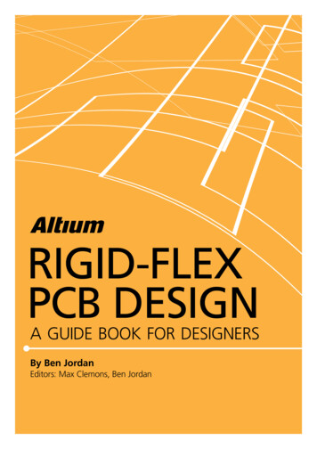
OrCAD PCB Design FlowSchematicElectrical EngineerBOMPCB LayoutManufacturing outputOrCAD PCB LibraryDesignSyncLayoutView, PlotFootprintLibraryGerber &DrillCIS-DB As you can see, OrCAD PCB Designer Flow consists mainly of two parts. These are the schematic capture module Capture and the layout module OrCAD PCB Editor. Both modules are supplemented by additional sub packages who represent in each combination anideal tool, enabling the user to complete all tasks with maximized efficiency.FlowCAD Confidential 4
Necessary Steps in SchematicFlowCAD Confidential 5
Necessary Steps in Schematic Steps described in this chapter give a brief overview. For Capture and Capture CIS separate quick start documents are available. Logic data already exists in training data and can be directly imported into a board-file as described inLab Import of Logic Information on page 72. Logic data required for PCB Editor quick start can be found at: \PCB Editor Demo 17 4\PCB Editor Demo\project2FlowCAD Confidential 6
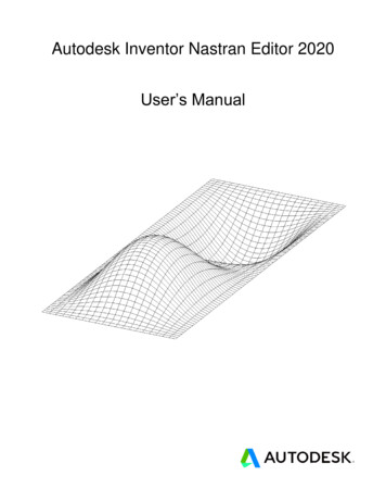
Capture Design FlowCreate a new project1.opjPlace and connect parts2Assign part references3U1ACheck design rules4U2A U3A.dsnU3BU3BAdd inter-sheetreferences5HS / SHT2Cross reference report6XREF8Netlist7Generate Bill of Materials9U2AU3AVCCEdit part and net propertiesSEL / SHT3Design Sync with jklh68766543swertU2AU3BVCCU3AGNDWIDTH “40”U1AU3 U3ABCOMPGROUP “1”Backannotate from PCB design10U1AU2AU3A U2BVCCGNDFlowCAD Confidential 7
Capture Design Flow Graphic on page 7 illustrates typical design flow creating a schematic for following PCB design.Points 1 to 10 illustrate individual work steps in design flow focusing on next pages. Main task starts with project creation and is completed with PCB layout synchronization. For surethere are other tasks during design process necessary like report generation, bill of materialgeneration, etc. Like wise it can happen that required parts are not in library. In this case a not illustrated part creationstep in between is necessary. We will focus on this step later.FlowCAD Confidential 8
Schematic TemplateGoal of design flow is, as already mentioned in introduction, to design a PCB layout based on anexisting schematic.Please see below schematic used for our demo example.More details regarding Capture flowcan be found in Quick Start Capturedocument.FlowCAD Confidential 9
REFDES – FootprintsIn list below we have listed footprints of individual parts manually assigned to parts in schematic.Footprints are symbols of electronic parts used in layout tool. T1 ERA-EI30-2 8VA D1 SM GL BRUECKE U1 TO220abv R1 SMR 1206 R2 VRES34 L1 SML 2220 C1, C2 Cpol 508 C3, C4 SMC 1206Please ensure correct spelling.FlowCAD Confidential 10
Start of CaptureAfter starting Capture,Capture Session Frame window will open.Start via:Start All Programs Cadence Release 17.4 OrCAD Products Capture CISorLinkIcon on desktopAt bottom of the window Session Log windowappears. It can be viewed also in a separatewindow. All events of current session andmessages from other Capture tools are listed here.File Open Project will open an existingproject, in which design (Power Supply) is defined.FlowCAD Confidential 11
Layout CreationLogic data gets transferred via PCB NewLayout into new PCB. PCB Layout Folder: Folder for netlist data Input Board File: A base or predefinedboard template Board: New generated board fileFlowCAD Confidential 12
PCB Editor Flow OverviewFlowCAD Confidential 13
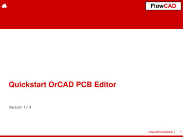
PCB Editor Flow OverviewCapture / CISForward AnnotationLibrariesLayoutBack AnnotationBoard Design SetupDrawing ParameterBoard TemplatePackage SymbolPadstacksMech. SymbolFormat SymbolShape SymbolFlash SymbolComponent PlacementRoutingInteractiv / AutoroutingConstraints Spacing Physical DesignDesignRuleCheckShapesPower PlanesPost ProcessPlotsGerber &DrillReportsFlowCAD Confidential 14
User InterfaceFlowCAD Confidential 15
PCB Editor and CanvasTitle BarPull-downMenusIcons usStatusbarActive CommandActive LayerCursor PositionApplication ModeFlowCAD Confidential 16
Icons and ToolbarsHere you can see all available icons of PCB Editor. They are bundled in groups, so-called toolbars.View Customize Toolbar allows to view or hide toolbars.Like in Windows, toolbars can be arranged along outer edges of window or in a separate location.FileEditUndo / RedoLinie / TextFix / UnfixSetup (Color,Constraints)DisplayZoomRoute3D ViewRats on / offPlaceShapesManufactureUpdate DRCNoteWhen you hover with curser over an icon, a short description will be displayed.FlowCAD Confidential 17
Control Panels and World View Window (I) Options Tab Shows current parameters and values foractive command. Shows fields to control active commands. Find Tab (Find Filter) Controls which objects can be selected. You can also select objects by entering their name. Visibility Tab Controls visibility of routing objects (Etch, Pin, Via,DRC) on conductor and plane layers.FlowCAD Confidential 18
Control Panels and World View Window (II)RMBView WindowTip Shows actual view section relative to entiredesign. Allows active view of partial areas of design.For larger working area all windows can beclosed separately(View Windows or via).Command Window Allows coordinate / command entry and showssystem messages.FlowCAD Confidential 19
Zoom Control with Middle Mouse ButtonMiddle mouse button provides you a universal tool to zooming and panning on work window.1 Circle in the middle represents original2 Arrows represent direction of mouseselection point. 1st click with middlemouse button (MMB).movement and following 2nd click (MMB).Zoom PrevZoom by PointsZoom by PointsZoom CancelZoom FitZoom OutZoom OutZoom Out3 Press middle mouse button (MMB) and move mouse. This is the way to pan actual view.4 A double click (MMB) will execute command Zoom Center.FlowCAD Confidential 20
Aliases, Function Keys and StrokesAliases, Function keys and strokes allow to execute complete commands or even macros with one click.Try to perform following examples as alias, function key and stroke:1. Load board sample.brd (folder sample).2. Type following commands, one after other, in command window and confirm with ENTER. alias Home zoom fit (Assignment of ZOOM Fit on Pos1-key. Please ensure correct large and lower case). funckey r iangle 90 (Assignment of 90-degree rotation on R-Key. Please ensure correct large and lower case).3. Use middle mouse key to zoom into a small area.4. Press key Pos1 (or Home using an English keyboard). Command Zoom Fit will be executed.5. Choose Edit Move and select a component.6. Press key R multiple times. Component will rotate by 90 degree every time.7. Press RMB Done.8. Press Ctrl key and at same time RMB – draw a small Z over a component.9. Command Zoom in will be executed.You have successfully defined an alias and a function as well as a stroke function executed.Type alias in command line and ENTER. All default aliases and function keys will be displayed.Select Tools Utilities Stroke Editor. Stroke editor will start and show all predefined strokes.TipTwo assignments above are only present in current session. How to define this kind of assignmentpermanently, will be explained in next chapter.FlowCAD Confidential 21
WorkspaceFlowCAD Confidential 22
PCB Editor Data StructureA Board File (xyz.brd) is collection of many drawing layers. Each of these layers can be switched visibleor invisible. Each layer can be assigned a color.PCB Editor is managing these drawing layers within a hierarchy of folders, classes and subclasses.Folders are a collection of classes to support users controlling colors and visibility.All elements are stored in kind of a 2-level database. First level is referencing to different predefinedclasses. Some dedicated classes are combined in specific folders.Folders and classes can neither be deleted nor can new ones be added.Within each class there are multiple subclasses. Subclasses are second level of database. They arecalled layers in the design. Predefined subclasses can not get deleted. You can add as many newsubclasses as you want. These can get deleted if they do not contain any data.All routing activities are related to subclasses assigned to class Etch. These subclasses have specialDRC properties assigned unlike other classes and subclasses.For each electrical layer of the board you must add an appropriate subclass. This means, for a 4-layermultilayer you need 4 subclasses under class Etch.A new defined PCB board is by default generated as a 2-layer board consisting of top and bottom.Predefined subclasses top and bottom can not get renamed or deleted.FlowCAD Confidential 23
Folders, Classes and Subclasses (I)FolderClassesSubclassesDisplayTemp Highlight, Grids, Ratsnest (top,bot, thru), Perm Highlight, WaivedDRCs, Drill holes, Via Label,Stacked via Label, Background,Pattern, Shading, TransparencySubclasses nicht vorhandenStackup /ConductorPin, Via, DRC, Etch, Anti Etch,BoundaryTop, Bottom(and all other user defined PCB board design layers)Stackup /Non ConductorPin, Via, DRC, Etch, Anti Etch,BoundarySoldermask Top, Soldermask Bottom, Pastemask Top,Pastemask Bottom, Filmmasktop, Filmmaskbottom,Through All, Package Top, Package BottomAreasRoute Keepout, Via Keepout,Package Top, Bottom, Through All,Package Keepout, Package Keepin,Route Keepin, Constraints RegionTop, Bottom, Inner Plane Layers, Inner Signal Layers,Outer Layers, Through AllBoard GeometryBoard GeometryOutline, Plating Bar, Assembly Notes, Tooling Corners,Dimension, Place Grid Top, Place Grid Bottom,Top Room, Bottom Room, Both Rooms,Switch Area Top, Switch Area Bottom, Silkscreen Top,Silkscreen Bottom, Assembly Detail, Soldermask Top,Soldermask Bottom, Off Grid Area, NcroutePath,Wb Guide LineFlowCAD Confidential 24
Folders, Classes and Subclasses (II)FolderClassesSubclassesPackageGeometryPackage GeometryAssembly Top, Assembly Bottom, Place Bound Top,Place Bound Bottom, Pin Number, Pad Stack Name,Silkscreen Top, Silkscreen Bottom, Body Center,Soldermask Top, Soldermask Bottom, Display Top,Display Bottom, Modules, Dfa Bound Top,Dfa Bound Bottom, PasteMask Top, PasteMask BottomEmbeddedGeometryEmbedded GeometryAllComponentsComp Value, Device Type, Ref Des,Tolerance, User Part NumberAssembly Top, Assembly Bottom, Display Top,Display Bottom, Silkscreen Top, Silkscreen BottomManufacturingManufacturingAutosilk Top, Autosilk Bottom, Ncdrill Legend,Ncdrill Figure, No Gloss All, No Gloss Top,No Gloss Bottom, No Gloss Internal, No Probe Top,No Probe Bottom, Photoplot Outline, Probe Top,Probe Bottom, Xsection ChartDrawing FormatDrawing FormatDrawing Origin, Outline, Revision Block, Revision Data,Title Block, Title DataAnalysisAnalysisLow Isocontour, Medium1 Isocontour,Medium2 Isocontour, Medium3 Isocontour,High Isocontour, Pcb TemperatureFlowCAD Confidential 25
Folders, Classes and Subclasses (III)To add additional layers (subclasses) to PCB, desired class should be selected in pull-down menuSetup Subclasses. Name of new subclass can be defined in subsequent windows.With exception of routing layers (Etch)all user defined layers can be entered viathese menus. When you choose ETCH, Layer Stackup will be started automatically to define additionalrouting layers. More details on this topic can be found at page 146 under Masterboard.All user defined layers have a white background to highlight user defined layers in menus. All other layersare default layers of system. One click on arrow button will delete a user defined layer.Only layers without any data can be deleted.FlowCAD Confidential 26
Control of Color and Visibility (I)Via Display Color Visibility orbe set.visibility and color of individual layers (classes / subclasses) tionFlowCAD Confidential 27
Control of Color and Visibility (II)Via Display Color Visibility orbe set.Color /Visibilityof designlayerNet colorsvisibility and color of individual layers (classes / subclasses) canGeneral displaysettings ofworking areaUser defined favorites(via RMB click in layer tab)Definition ofVisibility PaneTipIn display settings you also have functions like shadow mode and transparency for individual appearanceof design.FlowCAD Confidential 28
Option Window of Control PanelParameters in option window depend on respective command and offer a variety of options for respectivecommands. You should therefore always keep an eye on window option during interactive work.Route Connec
Aliases, Function keys and strokes allow to execute complete commands or even macros with one click. Try to perform following examples as alias, function key and stroke: 1. Load board sample.brd (folder sample). 2. Type following commands, one after other, in command window and confirm with ENTER.