Transcription
THERMAL STORAGE VESSEL SIZINGThis is a free article provided by www.homemicro.co.ukThermal Storage Vessel SizingDocument: lzc buffer Revision: 16.03 www.homemicro.co.uk LZC Articles on LZC technologies, HVAC, Computers & CAD too!Page 1 of 18
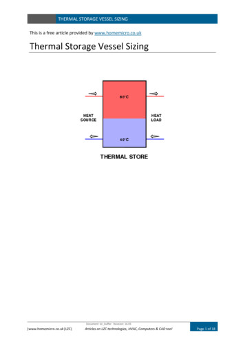
THERMAL STORAGE VESSEL SIZINGSummaryThis article provides information on sizing a thermal storage vessel. A buffer vessel orthermal store, captures heat to provide a buffer between load variations and improvesthermal efficiency.Tags: homemicro.co.uk; buffer vessel; thermal store; biomass boiler; ASHP; GSHP; Sizing a buffer vessel;accumulator tank; heating vesselThe web article relating to this subject can be found here:http://www.homemicro.co.uk/lzc vessel.htmlThe rights of publication or translation are reserved.Confidentiality StatementThis document shall be held confidentially and not disclosed to third parties without the prior written consent of theauthor. Homemicro.co.uk permits you to use the Homemicro.co.uk websites for non-commercial purposes only, unless youhave an Agreement with Homemicro.co.uk which states otherwise. The content and downloads that is made available toyou, are protected by copyright. They may not be copied, distributed, hired, leased or used in any other way other than fornon-commercial purposes, unless you have an Agreement with Homemicro.co.uk that states otherwise.Copyright www.homemicro.co.uk 2016DisclaimerWhile every care has been taken in the compilation of this information, Homemicro.co.uk will not be held responsible forany loss, damage or inconvenience caused as a result of inaccuracy or error within. Although care has been taken to ensurethe accuracy, completeness and reliability of the information provided, homemicro.co.uk assumes no responsibilitytherefore. The user of the information agrees that the information is subject to change without notice. Homemicro.co.ukassumes no responsibility for the consequences of use of such information, nor for any infringement of third partyintellectual property rights which may result from its use. In no event shall homemicro.co.uk be liable for any direct,indirect, special or incidental damage resulting from, arising out of or in connection with the use of the information.Document: lzc buffer Revision: 16.03 www.homemicro.co.uk LZC Articles on LZC technologies, HVAC, Computers & CAD too!Page 2 of 18
THERMAL STORAGE VESSEL SIZINGContentsSummary . 2Contents . 3List of figures . 3List of tables . 3INTRODUCTION . 4MANUFACTURERS ADVICE . 4BENEFITS . 4PUBLICATION ADVICE . 5INFORMATION REQUIRED. 7SIZING . 7Method 1 – Rule of Thumb litres per kW . 7Method 2 – Minimum Operating Time. 8Method 3 – Smallest Zone . 8Method 4 – Flow Rate Percentage . 9CAPACITY. 9STORED ENERGY . 10ASHP . 10BIOMASS . 11CHILLED WATER . 11CHP . 11GSHP. 12HEAT PUMPS . 12SOLAR THERMAL . 12LOCATION OF VESSEL . 12CONTROL . 13STRATIFICATION . 14ISSUES . 15DEFINITIONS. 16SPECIFIC HEAT CAPACITY . 17CONVERSIONS & DATA . 17List of figuresFigure 1 - Buffer vessel used with an ASHP . 13Figure 2 - Thermal store with a biomass boiler . 13Figure 3 - Thermal layering in a thermal store. 14Figure 4 - Mixing in a buffer vessel . 15List of tablesTable 1- Information contained in publications. 5Table 2- Water specific heat capacity . 17Document: lzc buffer Revision: 16.03 www.homemicro.co.uk LZC Articles on LZC technologies, HVAC, Computers & CAD too!Page 3 of 18
THERMAL STORAGE VESSEL SIZINGINTRODUCTIONThis guide provides information on the sizing of thermal storage vessels. The termsaccumulator, buffer vessel, thermal store, tank and cylinder are often used interchangeably(see Definitions), including in this guide. Essentially the advice in this guide is on buffervessels and thermal stores used to maximise thermal efficiency and provide plantprotection.A buffer vessel is a vessel that holds water, increasing the overall volume content of theheating distribution system. The additional water volume absorbs heat (thermal storage)produced by the heating appliance in low load conditions, which the building or system doesnot yet require principally to prevent plant short cycling. The vessels also provide hydraulicseparation between primary and secondary circuits. Buffer vessels are also used withchilled water systems for the same reasons.This guide outlines factors that affect the selection and sizing of buffer vessels for a varietyof different heat sources to include heat pumps, biomass boilers and combined heat andpower plant.MANUFACTURERS ADVICEConsulting equipment manufacturers for best advice is strongly recommended.Manufacturers’ advice will be invaluable to ensure the most appropriate type of vessel andcontrol regime is provided for a particular application. Variable methods of control anddifferences in turn-down ratios means that no two items of plant will have the sameoperating requirements. As an example, a 900kW chiller manufactured by Carrier requires aminimum system water content of 4,600 litres, whereas Airedale manufacture a chillerrequiring a water content of only 1,350 litres.BENEFITSAs stated above, terminology used to reference thermal storage vessels is often usedinterchangeably. For the purpose of this guide, there are two vessel variations:Buffer Vessel: Used to capture residual heat on shut-down to improve system efficiency Dissipate heat from boiler on shutdownProtects boiler from overheatingImproves overall efficiencyStored heat can be used by boiler on start-upThermal Store: Enables a small boiler to serve a system with a higher capacity Boiler can be sized at less than 100% of the system heat demandAllows boiler to operate continuously for long periodsWill serve function of a buffer vessel (takes heat on shut-down and feeds boiler onstart-up as required)Document: lzc buffer Revision: 16.03 www.homemicro.co.uk LZC Articles on LZC technologies, HVAC, Computers & CAD too!Page 4 of 18
THERMAL STORAGE VESSEL SIZINGBuffer vessels extend the life of plant by preventing short cycling. Short cycling willparticularly occur at times of low heat demand when the plant will produce heat at a fasterrate than can be used by the system. The system water temperature will therefore risequickly, shutting down the plant after only a short operating period.The buffer vessel acts as a store to absorb part of the heat generator (boiler, heat pump,etc.) output when the system load is below the minimum operating output of the plant. Thisstored heat is then used at the start of the heating period each day when the buffer willdischarge in a controlled manner to satisfy part or all of the initial peak heat demand whilethe central plant heats up. The stored heat can also serve as a preheat to the plant.A thermal store also provides a heat sink in order that heat pumps can take advantage oflower night time electricity tariffs and possibly lower energy costs (not a clear cut matter).Used with a CHP, a buffer can provide a thermal store during periods of low heat demand toprevent [waste] heat having to be dumped.PUBLICATION ADVICEInformation from a collection of published technical sources is detailed in Table 1. Specificguidance is limited in detail, and at best only prescribes rule of thumb parameters. There isno one size fits all solution as system design and use can vary significantly.Table 1- Information contained in publicationsSourceInformation ProvidedBS EN 14511:2011Recommends the heat pump should not start more than three times in anhour. This is due to the relatively high starting current of the compressordrive motor and the impact this may have on the local electricity supplyinfrastructure. Also for the purpose of defrosting, and as a guide, thecapacity of the buffer tank should be based on approximately 25 litres perkW output of the heat pump.BS EN 15450:2007Design of heat pumpheating systemsp.20 (4.5) “A higher inertia (capacity) can be achieved by installing abuffer storage (in parallel or series). A buffer storage connected in parallelwith the heat pump serves additionally as a means of hydraulicdecoupling. A guidance value for sizing the buffer storage volume is 12 to35 l per kW maximum heat pump capacity”BSRIA 7/2009 HeatPumps (BG7)p.37 includes statement: “It [a buffer vessel] is most likely needed forradiator, fan coil and air-handling-based heat distribution systems wherethe system has limited storage capacity.”p.38 provides a formula for calculating a buffer volume size based uponminimum operating time. Refer to equation 1.Guidance indicates buffer vessel located in return feed to heat pump.Energy Saving TrustCE299 (2008), theapplicability of districtheating for newdwellingsp.15 CHP – “ thermal storage is normally required to match the heatoutput of the CHP with the heat demand profile.”p.20 Biomass – “Higher levels of biomass penetration will require a greateramount of thermal storage to smooth the heat demand.”Document: lzc buffer Revision: 16.03 www.homemicro.co.uk LZC Articles on LZC technologies, HVAC, Computers & CAD too!Page 5 of 18
THERMAL STORAGE VESSEL SIZINGCarbon Trust CTG012(2009) Biomass Heatingp.46 “Where a biomass plant is the only item of heating plant, installing abuffer tank (heat store) can smooth out its running profile”p.46 “Seasonal load conditions – .If the heat load is below the lower limitthat the biomass plant can provide (typically 20-30% of the plant rating),this can lead to short-cycling. The inclusion of a heat store can avoidthis. . improving performance and reducing maintenance issues.”p.41 Batch-fired
As an example, a 900kW chiller manufactured by Carrier requires a BENEFITS As stated above, terminology used to reference thermal storage vessels is often used File Size: 1MBPage Count: 18