Transcription
AdvancedTECH GUIDEPAVING STONES RETAINING WALLS
ACKNOWLEDGEMENTSThe content of this manual was developed using the vast experience acquiredby the Unilock sales force during more than 40 years in the precast concreteindustry.Unilock has attempted to ensure that all information contained in this guideis correct. However, there is the possibility that this guide may contain errors.Review all critical designs with your local Unilock representative prior toconstruction. Final determination of the suitability of any information or materialis the sole responsibility of the user. Products mentioned herein are subject toregional availability. Check for product availability at your Unilock location. 2006-2013 Hengestone Holdings, Inc.Hengestone Holdings, Inc. is the owner or authorized user of all trademarkslisted herein.iUnilock
TABLE OF CONTENTSACKNOWLEDGEMENTSTABLE OF CONTENTSINTRODUCTIONOverview of Interlocking Concrete PavementsConceptAdvantagesComponentsTypical cross sectionsOverview of Segmental Retaining WallsConceptAdvantagesComponentsPAVER AND WALL INSTALLATIONDesign and PlanningSketch or planEngineering design and certificationFlow of materialsUtilities locationBase ConstructionLayout for excavationExcavationSoil conditionsSite drainageSoil compactionBase installationQuality of base materialsBase thicknessBase compactionPAVER INSTALLATIONEdge RestraintsEdge restraint installationBedding CourseBedding course installationPavers InstallationManual installationStep-by-step manual paver installationMechanical installationTech 2325262728ii
TABLE OF CONTENTSCuttingCutting toolsBorders and AccentsCompacting paversJointing SandCleaning and finishingGRAVITY RETAINING WALL INSTALLATIONBase preparationInstalling the first courseStack unitsBackfillCoping UnitFinish gradingREINFORCED RETAINING WALL INSTALLATIONGeogrid reinforcementBackfill over geogridDETAILSSplittingCornersOutside cornersInside cornersCurvesInside curvesOutside curvesStepsMost common configurationsSteps installation tipsPlantersPillarsPAVERS MAINTENANCE GUIDECleaningGrease and oil stainsEfflorescence on concreteRust stainsTar, rubber and paint stainsSealingSolvent and water base protective sealerJoint sand stabilizer and paver sealerSpecialty joint sands and EasyPro jointing compoundUse of chemicals & 45454546475051525353545455555556565657Unilock
INTRODUCTIONAs North America’s premier paving stone and retaining wall manufacturer, Unilock is adynamic organization at the forefront of the commercial and residential concrete landscapeproducts industry. Our exclusive range of products, services and expertise is continuallyexpanding. Whether you are building a complete streetscape or a residential walkway,patio or driveway, Unilock can provide you with a range of shapes, colors and texturessecond to none within the precast concrete industry. Be sure to use Unilock productsmade with EnduraColor and EnduraColor Plus . Visit our website to learn more.This manual is a basic guide for the construction of any type of project involving pavingstones and segmental retaining walls. Hands-on training is also available at Unilock Installation & Design Seminars. For a listing of seminars near you, visit www.unilock.com.Overview of Interlocking Concrete PavementsConceptInterlocking concrete pavements are generally composed of a surface consisting ofprecast modular concrete units of varying shapes, colors and textures. These areplaced over a graded sand and gravel base and interlocked with bedding and jointsand, which can be constructed over a variety of sub-bases. Because they work as aflexible pavement, they can flex with minor movements in the base without cracking,making them an ideal pavement for North America’s climate. This uniqueness givesthem a distinct advantage over asphalt, poured and stamped concrete.AdvantagesConcrete paving stones offer a great variety of advantages over all other types ofpaving products. Durability - The combination of high density, high compressive strength andlow absorption rate makes concrete paving stones highly resistant to saltscaling, a common problem with some types of concrete. EnduraColor andEnduraColor Plus products from Unilock take performance and aesthetics toa whole new level. Learn more at www.unilock.com.Reusable - If the pavers must be removed in order to correct a pavementproblem, or to allow utility installation or repair, the pavers are completelyreusable.Aesthetics - The visual impact of paving stones adds character and charmto any installation. With interlocking pavers, color, shape and texture can beincorporated to complement any project design.Freeze-thaw resistance - Frost damage is virtually nonexistent. The jointsbetween the paver units absorb any movement caused by frost.Tech Guide1
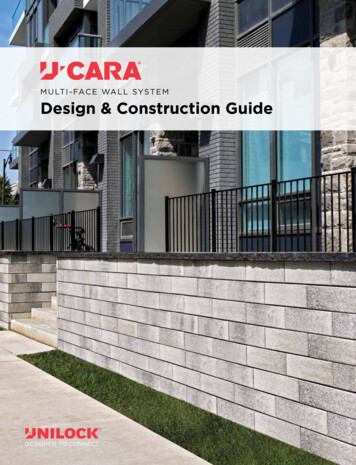
Below ground access - Pavers can be removed and reinstalled without anyvisual or functional changes. This is ideal for utility access below ground.Skid resistance - The surface texture of pavers gives superior traction inpedestrian, automotive and pool applications.Economics - Paving stones offer an economical alternative to other types ofpavement especially over the long term. When maintenance and replacement costs are considered, other forms of paving are usually moreexpensive.Maintenance - With proper installation, pavers require low maintenance.Accessories - Accessory products for pavers, such as lights, are availableto transform outdoor spaces into more functional areas.Modularity - Paving stones can be installed in a variety of patterns,including curves, straight lines and intricate designs, and add vitality toalmost any environment. The combination of compatible shapes, sizes andcolors gives the installer the opportunity to do “Paver Quilting”.Ready to use - They may be used immediately upon completion INTERLOCKUNILOCK CONCRETEPAVERS WITHSAND FILLED JOINTSCOMPACTEDAGGREGATE ORSTABILIZED BASETO SUIT TRAFFICAND TILE ASREQUIRED BYDESIGNFigure 1. Typical components of an interlocking concrete pavement system.The unique aspect of concrete pavers is that they interlock to help spread any loadpoints. There are three ways pavers interlock: Vertical, Horizontal, and Rotational.(Figure 1) Vertical interlock is achieved by the shear transfer of loads to surroundingunits through the sand in the joints. Horizontal is maintained by the pavers being ofsufficient thickness, placed closely together, and restrained by a curb from lateralforces. Rotational interlock is achieved through the use of laying patterns thatdisperse forces from braking, turning and accelerating vehicles.2Unilock
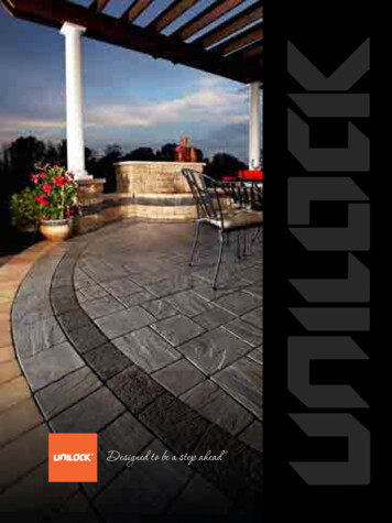
Typical cross sectionsUNILOCK EDGERESTRAINT (BURIED)JOINTING SANDUNILOCK PAVERSGRASSBEDDINGSANDTOPSOILCOMPACTED 3/4"CRUSHER RUNGRAVELGEOTEXTILE ASREQUIRED BY DESIGNCOMPACTEDSOILSUBGRADEMINIMUM 6"- 8" (150-200MM)Figure 3. Paver installation with PVC or aluminum edge restraintCONCRETE CURBUNILOCK PAVERSJOINTING SAND1" THICK BEDDINGCOURSE OF 1/8"CLEAR CHIP STONEGRASSTOPSOIL14" (MIN) THICK BASEOF 3/4" CLEARCHIP STONE4" DRAIN PIPERECOMMENDEDAT LOWESTPOINT. MUST BECONNECTEDTO APPROPRIATEOUTLETGEOTEXTILE ASREQUIRED BYDESIGNMINIMUM 4"-6" (100-150MM)COMPACTED OR UNDISTURBEDSOIL SUBGRADECOMPACTED 3/4"CRUSHER RUN GRAVELFigure 4. Permeable paver installation with precast or cast-in-place curb unitRETAINING WALLUNITS & COPINGJOINTING SANDUNILOCK PAVERSBUILDING WALLUNILOCK CONCRETEADHESIVEBEDDING LAYER:1" THICK LAYEROF 1/4" STONECHIP (NO FINES)GEOTEXTILEIN-FILL AREA: 3/4"CLEAR CHIP STONE(NO FINES)GRASSTOPSOILCOMPACTED SOILSUBGRADECOMPACTED3/4" CRUSHERRUN GRAVELMINIMUM 4"-6" (100-150MM)OPTIONAL4" PERFORATEDDRAINAGE PIPEWATERPROOFMEMBRANEFigure 5. Patio/Terrace installation with wall units and copingTech Guide3
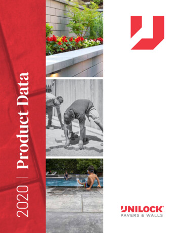
CONCRETE CURBUNILOCK PAVERSJOINTING SANDGRASS1" THICK BEDDINGCOURSE OF 1/8"CLEAR CHIP STONETOPSOIL4" - 6” REINFORCEDCONCRETE PAD WITHPOSITIVE DRAINAGEAWAY FROMSTRUCTURESMINIMUM 4"-6" (100-150MM)COMPACTEDSOIL SUBGRADEGEOTEXTILEOR FILTER FABRICFigure 6. Paver installation over cast-in-place concreteCaution: Pavers over ConcreteA bedding course of 1/8” clear chip stone on a concrete pad will provide the necessarydrainage required, but will provide little or no “give” when final compaction of the pavers isattempted. You also run the risk of damaging the pavers.Therefore we highly recommend that you make the necessary height adjustments (if any) tothe individual stone units to achieve a flat surface. You may attempt to compact any slightvariances out using a small vibratory plate compactor that is fitted with a protective pad.Cease any further compaction if damage occurs.4Unilock
Overview of Segmental Retaining WallsConceptAll Unilock’s retaining wall systems have been engineered to work on the basicpremise that the mass of the concrete units will counter the force of the soils beingretained. To achieve this, units are simply stacked on top of each other using a runnerbond pattern. The locking mechanism on each of the units interlocks with the unitsbelow. This creates a strong connection between the individual units, preventingsliding and bulging of the wall.Most Unilock retaining wall systems have a patented offset tongue-and-groovedesign, which ensures that each course is installed at the appropriate setback, furtherincreasing the wall’s stability. When the wall has been assembled, the retaining wallsystem remains flexible. This allows the wall to endure minimal settlement, deflectionand freeze/thaw movement.For the construction of walls less than 36” (1m) in height, where good soilconditions exist, the typical installation method described in this guide shouldbe used. When walls exceed this height, consult your local planning departmentand obtain professional engineering services.AdvantagesUnilock retaining wall systems offer a great variety of advantages over all othertypes of retaining wall products. Modularity - These walls are flexible, yet retain their structural characteristics.Unilock retaining wall units are easy to use and are dry stacking (nomortar required). They do not require special concrete footings to beinstalled. These multi-component systems allow for complete flexibility indesign and ease of installation. Freeze-Thaw Resistance - These walls can absorb minor movements dueto frost or settlement. Aesthetic - The visual impact of our retaining walls add character andcharm to any project. With Unilock retaining walls, color, shape andtexture can be incorporated to complement the landscape design. Components - Many components are included with Unilock retainingwalls. With these, it is easy to save time during installation and create auniform finished look for the wall. Maintenance - With proper installation, walls require virtually nomaintenance. Trouble-free Base - A compacted granular base is all that is required. Thisreduces cost by not requiring an expensive structural footing. Mechanical Installation - Some Unilock wall systems can be mechanicallyinstalled, reducing installation time and labor required.Tech Guide5
ComponentsCOPING UNITGRASSUNILOCKCONCRETEADHESIVETOPSOILRETAINED SOILWALL UNITINFILL GRAVELGEOTEXTILEPERFORATED DRAINWITH FILTER SOCKCOMPACTEDGRANULAR BASEEXISTING SITE SOILMUST BE UNDISTURBEDFigure 6. Conventional gravity structureCOPING UNITGRASSUNILOCKCONCRETEADHESIVEWALL UNITMAXIMUM HEIGHTAS SPECIFIEDBY DESIGNTOPSOILRETAINED SOILGEOGRIDAS SPECIFIEDBY DESIGNINFILL GRAVELGEOTEXTILECOMPACTEDGRANULAR BASEPERFORATED DRAINWITH FILTER SOCKEXISTING SITE SOILMUST BE UNDISTURBEDFigure 7. Typical components of a geo-grid reinforced retaining wall6Unilock
PAVER AND WALL INSTALLATIONDesign and PlanningSketch or planA well thought-out design, combined with proper planning, makes the installationproceed smoothly and ensures a quality installation. Proper planning and organizationwill reduce headaches and costly mistakes and will improve customer relations.It is recommended to elaborate on a plan, showing all measurements, diagrams andcross sections for all landscape elements. Elevation views and all details involved inthe project should be sketched as well.Engineering design and certificationWalls greater than 3’ (1 m) or with a heavy load must be engineered by a qualifiedengineer. Some municipalities require even lower heights, such as 2’ (600 mm), tobe designed by an engineer. Fencing or railing may also be required. Verify localcodes.Only “stamped” drawings from a qualified engineer should be used for your installation.A retaining wall is an engineered structure and must be installed as per engineeringguidelines. Failure to install its properly could result in wall failure, leading to propertydamage or personal injury. A failed installation is very expensive to remedy.The presence of slopes greater than 3:1 or other weights, such as vehicular trafficabove a wall, can adversely affect the wall’s performance. This needs to be identifiedfor appropriate engineering.Flow of materialsMoving material onto the site and balancing the flow of material before the job beginsare important to complete the job without delays. Planning the movement and timingof materials also affects the productivity of the crew.Consider where all materials need to be dumped or placed. Allow space on the sitefor their delivery. Avoid placing material away from the project area and hauling themin small quantities to the different areas. This wastes time. (Figure 8)Efficient handling of the pavers will affect the length of time taken to complete thebalance of the job. It is recommended to use a forklift or a paver cart so it is possibleto move a whole section of pavers at once. This tool will reduce labor costs and canpay for itself in a single job.Tech Guide7
COMPACTEDAND INSPECTEDAGGREGATE ORSTABILIZED BASEEDGE RESTRAINTCONSTRUCTEDON BASE COURSEBEDDING SANDSTOCKPILED AHEADOF SCREEDINGSAND BEDDINGCOURSESCREEDLAYING FACEUNCOMPACTEDPAVING UNITSLAIDPAVER BUNDLESPLACED AS CLOSEAS POSSIBLETO LAYING FACEPAVINGUNITSCOMPACTEDJOINTING SANDBEING PLACEDCUT INFILLUNITSPAVEMENTCOMPLETEDALLOW ACCESSFigure 8. Flow of material onto the job side8Unilock
Utilities locationFor personal safety of all crew members, make sure that all underground utilitieshave been located and clearly marked. Contact local utility companies to find anyunderground services, such as telephone, electricity, gas, cable TV, etc. Mark anystructures, such as water supply, irrigation piping, storm and sanitary sewer, etc.Base ConstructionLayout for excavationStake out the area - Before excavation begins, mark out the perimeter with paint,locating all elements, such as steps, planters, raised patios, etc., In order to geta “feel” for the design. This will make it easier for the crew working on the job tounderstand the scope of the project. Set measurements and stakes with anothercrew member as a “double-check”. (Figure 9) Changes sometimes need to bemade from the original plan due to certain site issues that were not addressed inthe original design.The perimeter of the paver and wall installation should be at least 8” (200 mm)greater than the actual area to be constructed. Mark the elevations on stakeswith string lines so that the depth of excavation can be checked as it progresses.Using a nylon mason’s line set the finished elevation of the pavement. Measure allexcavations and base thickness from these lines.BENCHMARKSTRING LINESEDGE OFEXCAVATIONSTRING LINES PULLEDTIGHT TO REQUIRED SLOPEAND ELEVATIONSMINIMUM 8"(200MM)WIDER THANEDGE OF PAVERSWOOD ORSTEEL STAKESFigure 9. Project layout and stakingTech Guide9
ExcavationThere are several factors associated with base construction that may impact the depthrequirements of the base. The depth of excavation depends on load requirements,drainage, existing soil conditions and paver or wall style and thickness. To determinethe depth of the excavation, use of the following tables is recommended.Table 3: Typical base thickness for paversPAVERSWELL DRAINED AREA/UNDISTURBED SOILPOORLY DRAINED AREA/DISTURBED SOILBEDDINGCOURSEPAVERTHICKNESSGRANULARBASE - (min)BEDDINGCOURSEGRANULARBASE - (min)Pedestrian TrafficPatios, Walkways,Pool Decks6” (100 mm)1” (25 mm)8” (150 mm)1” (25 mm)2 3/8” (60 mm)2 3/4” (70 mm)Vehicular TrafficResidentialDriveways10” (200 mm)1” (25 mm)14” (300 mm)1” (25 mm)2 3/8” (60 mm)2 3/4” (70 mm)2 1/8” (80 mm)Vehicular TrafficCommercial Areas14” (300 mm)1” (25 mm)20” (450 mm)1” (25 mm)2 3/4” (70 mm)3 1/8” (80 mm)Total Excavation Granular Base Bedding Course Paver Thickness - 1/2 ” (13 mm) for an uncompacted bedding thicknessTable 4: Typical base thickness for walls and required backfillWALLSGRANULARBASEUNIT THICKNESSBELOW GRADEGRANULAR BACKFILLWIDTHSteps, Planters, Raised PatioMinimum Height less than 18”(45 cm)Min. 4” (100 cm)Min. 3” (75 mm)Min. 8” (200 mm) 12” (300mm)Steps, Planters, Raised PatioHeight greater than 18” (45 cm)Min. 6” (150 cm)Min. 6” (150 mm)Min. 12” (300 mm) 18” (450 mm)Special Applications Pillars,Fountains, Water FeaturesMin. 6” (150 cm)Min. 6” (150 cm)N/ARetaining Wall ApplicationsMin. 6” (150 cm)Min. 6” (150 cm)Min. 18” (450 mm)Total Excavation Granular Base Unit Thickness Below GradeTable 4 is based on well-drained and undisturbed soils. The granular backfill dependson type of soil, drainage conditions, height and type of wall (gravity, reinforced orcrib)10Unilock
Soil conditionsWhen working in areas where there are poor soil conditions (e.g. heavy clay, disturbedsoils), there is the potential for surface deformation or settlement. Action must betaken to increase the depth of the base to provide more stability. Always remove anyloose or disturbed soils.Here are some quick field tests that can provide hints on the type of soil in the jobsite.Quick field identification - Using simple field tests like the “patty”, “shake” and “snake”tests, a good idea of the basic soil type can be obtained. For each test, take a soilsample and add enough water to make it into a “putty type” consistency. Form thesoil into a ball about the size of an egg. This is easily done for most clay and silt soils.Forming sandy soils may not be possible and may not be necessary since its grittytexture indicates its classification.For the “patty” test, flatten out a sample about 3/8” (10 mm) thick and let it dry in thesun. After it is dry, it will either break easily or be more difficult to break. If it is difficultto break, it has high clay content. If it breaks easily, it has a predominance of sandand silt in it.For the “shake” test, sup the ball of soil in two hands and shake vigorously for about30 seconds. If small drops of water are released to the surface and hands, there issome sand in the soil. If no water is released, the soil is clay or contains some silt.The “snake” test is done with clay or silt soils to determine how much water they willhold. This is seen by rolling the sample into a few moistened “snakes” about 3/8” (10mm) in diameter. If snakes can be made greater than 2” (50 mm) long, the soil haspotential to hold much water (high plasticity soil). If the snake falls apart before it rollsinto a 2” length, the soil is consider low plasticity and will drain water.Site drainageAll lines and final elevations of the pavement should slope away from the house orbuilding. The minimum recommended slope is 2% or 1/4” per every foot of pavement(20 mm per meter) as this will better facilitate drainage. (Figure 10) The maximumslope for comfortable walking is 7 degrees or about 12%. Note: 8% is the steepestslope for pedestrian accessibility.Grading of the base material is often done with a large landscape rake guided byseveral string lines. Larger areas may require the use of a transit (surveyor’s level) toaccomplish more delicate grades.Tech Guide11
STAKEBEDDING SANDLINE LEVELSTRING LINE100"3"5"COMPACTEDAGGREGATE ORSTABILIZED O OR WALKWAYALWAYS SET RUNOFF AWAYFROM EXISTING BUILDINGSFigure 10. 2% is the minimum recommended slope for site IONFLOW OF WATERFigure 11. Runoff should always be directed to the lowest elevation.12Unilock
Downspouts - Rerouting downspouts (Figure 12) so that the roof water is divertedaway from paved areas is an inexpensive insurance for protecting the integrity of theinstallation and it is easy to do early on in the project. The trenches may need to beexcavated manually so a proper slope can be put on the pipe.Drainpipesshouldbesurrounded by gravel so thearea remains as frost-free aspossible. A minimum of 3” (75mm) of gravel should alwayssurround the pipe. To avoidsettlement, always compactwell trenched areas.ROOFEAVESTROUGHBEDDING SANDFigure 12.DownspoutTO EXIT ATAPPROPRIATELOWER GRADECOMPACTED SOILSUBGRADEUNILOCKCONCRETEPAVERSDOWNSPOUTHOUSE BRICKNON-PERFORATEDDRAIN PIPECOMPACTEDAGGREGATE ORSTABILIZED BASESoil compactionOnce an area has been excavated, the soils at the bottom must be compacted priorto the placement of the new base material. It is important to spend as much time aspossible compacting to achieve good compaction. Insufficient compaction may resultin settlement.Compaction achieves four main purposes. It increases the load-bearing capacityof the soil, prevents settlement/rutting, reduces seasonal movement from moisturechanges and freeze-thaw cycles and helps ensure that movement during freeze-thawcycles in uniform.Avoid compacting excessively wet or dry soils. Every soil has optimum moisturecontent. Higher or lower water content than optimum produces lower density duringcompaction. The optimum moisture content in relation to density of a soil is normallytested in a soil laboratory using the Standard Proctor Density (SPD) test.Compaction moisture content field test - For non-commercial applications, the “drop”test is a simple soil moisture content field test. Prior to soil compaction, remove asample from the newly excavated subgrade surface and press it into a tennis-ballsized clump. Hold the ball about 2’ (600 mm) above a flat rigid surface and drop it. Ifthe sample breaks into at least three or four equal size particles, it is close to optimummoisture content and ready to compact. If it breaks into many small pieces, it is toodry and water may need to be applied to the soil prior to compacting. If the ball doesn’tbreak at all, it is too wet and the soil will likely need to dry prior to compacting.Tech Guide13
Right equipment - The best way to compact cohesive soils, such as clay and silt, iswith a low amplitude vibratory roller or rammer (Table 5) as they effectively removeair and force the particles closer together. For very heavy clays, a minimum 5,000 lbf(21 kN) reversible plate rammer is recommended. Adding a thin layer of base material(1/2” - 10 mm) over stable but sticky clay can reduce compaction time.Non-cohesive soils, like sands and sandy gravels, compact best with vibratory platecompactors and vibratory rollers. It’s recommended to use large plate compactors, atleast 4,000 lbf or 18 kN, or a walk-behind vibratory roller. For larger jobs, a ride-ondouble drum roller compactor with 7,000 lbf to 9,000 lbf (30 to 40 kN) is suggested.Soft spots - Sometimes during compaction, soft spots will become apparent, especiallyin heavy clay soils. In these cases, it will be necessary to remove the soil and replaceit with suitable base material and compact it.Table 5. Soil compaction equipmentRammer(7,000 lbs)Medium Compactor(4,000 lbs)Large Compactor(5,000 lbs)Base installationGeotextiles - Installation of geotextile (filter fabric) over cohesive soils, i.e. clays orsilts, is highly recommended. It is also a good option for use over soils that staysaturated for a large portion of the year. The fabric separates the “fines” in soils fromthe granular base and prevents them from migrating upward into their base, resultingin reduced base performance.Geotextiles do not typically increase the load-bearing capacity of a pavement or aretaining wall. Rather, they retain the intended load-bearing capacity. They can beconsidered inexpensive insurance for extending the life of a compacted base. Theydo not allow for a reduction of base thickness.14Unilock
Installing geotextiles around the perimeter will also prevent migration of adjacent soilsinto the base material. Cover the sides with fabric and fasten it to the ground withmetal staples while removing all wrinkles. Excess fabric and exposed staples canbe removed once the job is completed. When installing geotextiles, it is important tooverlap them in the direction of the grade by placing the fabric at the lowest elevationfirst, and working up to the higher elevation next.Base installation - Like soils, the right amount of moisture in the base material ensuresreaching maximum density during compaction. Most crushed aggregate basesrequire about 5% to 6% optimum moisture content to reach 100% Standard ProctorDensity. If the aggregate is dry, spread and moisten by spraying before compacting,allowing the water to penetrate to the full depth of base thickness.When the aggregate is not at its optimum moisture throughout the lift thickness, thereis a risk of compacting only the top portion of the base. As a result, it will not compactto maximum density and pavement settlement may occur in the future. In contrast,adding excessive water can create pumping of the aggregate under moisture contentof the aggregate in the field, grab a handful and squeeze it tightly for a few seconds.After opening the hand, a good sign of the right amount of moisture is that theaggregate is sticking together with no water draining.When installing the first layer of aggregate, it is important not to compromise theintegrity of the geotextile with wrinkles. Place the first aggregate lift ahead of theloader wheels, ensuring that the equipment does not drive directly over the geotextile.This also reduces the risk of tearing or puncturing the fabric.Quality of base materialsSpecifications typically used by cities, states or provinces for dense gradedaggregate base materials under flexible asphalt pavements are generally adequatefor pavers. These specifications can be obtained from engineering departments. If nospecifications are available, then use the recommended grading for aggregate basesin accordance with ASTM D 2940. (Table 6)Table 6: ASTM D 2940 - Standard Specification for Graded Aggregate Material for Bases or Subbases for Highways and AirportsSIEVE SIZEPERCENT PASSINGJOB MIX TOLERANCEBASESSUBBASESBASES2” (50 mm)100100-2-31 1/2” (37.5 mm)95-10090-100 5 53/4” (19 mm)70-92 83/8” (9.5 mm)50-70 8No. 4 (4.75 mm)35-55No. 30 (600 μm)12-55No. 200 (75 μm)0-8Tech Guide30-60 8SUBBASES 50-12 3 15
Base thicknessThe thickness of the base is determined by traffic loads, soil strength, subgrade soildrainage, moisture and climate. A qualified civil engineer familiar with local soils andtraffic conditions should be consulted to determine the appropriate base thickness forstreets, industrial pavements and critical retaining wall installations.Minimum base thickness guidelines that apply to most areas in North America areshown in tables 3 and 4 (Page 10). Greater thicknesses for the listed applications areoften used in regions with numerous freeze-thaw cycles, expansive soils or very coldclimates.Base compactionRake and grade the base to string lines so that the base will compact to a uniformthickness and to the planned slope. This can be done with the backside of a gradingrake (sometimes called a “lute”). The rake helps prevent aggregate segregation oflarger particles from smaller ones, which reduces the compacted density. Gardenrakes are not appropriate for spreading base aggregates.Individual base lifts (layers) should be installed in uniform thicknesses to preventwaste and help ensure uniform density. A thickness tolerance of 3/4” (19 mm) to 1/2”(13 mm) is recommended for the final base thickness. Too much aggregate wastestime and money. Too little aggregate can create a base with reduced support.The total number of passes to accomplish full compaction to the required proctordensity depends upon the weight and travel speed of the compactor. See table 7 forguidelines regarding maximum lift loads and minimum number of passes. A good fieldindicator that full compaction has been reached is that your compactor will begin tobounce slightly as opposed to the regular vibration.Table 7: Compaction equipmentSmall Compactor (3,000 lbs) - 3”(75 mm) maximum lift thickness.Minimum 3 passes per layer.16Medium Compactor (4,000 lbs) - 4”(100 mm) maximum lift thickness.Minimum 2 passes per layer.Unilock
Large Compactor (5,000 lbs) - 6”(150 mm) maximum layer thickness.Minimum 2 passes per layerRammer (7,000 lbs) - (Unconfined)6” (150 mm) maximum lift thickness.Minimum 2 passes per layerRammer (7,000 lbs) - Confined) 8”(200 mm) maximum lift thickness.Minimum 2 passes per layer.Vibratory Roller (9,000 lbs) - 8” (200mm) maximum layer thickness. Minimum 2 passes per layer.When compacting soils or base materials, compact first in one direction (PerimeterCompaction), then compact the entire area again with passes perpendicular toprevious ones (Lateral Compaction). Overlap should be about one third the width ofthe plate compactor base. (Figure 14)Tech Guide17
HOUSEGARAGEPerimeter CompactionHOUSEGARAGELateral CompactionFigure 14. Compaction directions.18Unilock
There are some indicators that the point of nearly complete compaction is beingreached: When the compactor starts “crabbing” (moving in a sideways motion)The “spike test” - where it takes at least a three pound (1.5 kg) hammer to drivean 8” or 10” (200 mm - 250 mm) long spike into the base.Co
Unilock retaining wall . cross sections for all landscape elements. Elevation views and all details involved in the project should be sketched as well. Engineering design and certification Walls greater than 3’ (1 m) or with a heavy load must be engineered by a qualified engineer. Some