Transcription
Introduction to Arduino// Basic Arduino reference sheet:Installation: Arduino: http://www.arduino.cc/en/Guide/HomePage Fritzing: http://fritzing.org/download/Support: Arduino: http://www.arduino.cc, http://www.freeduino.org, google.com Fritzing: http://www.fritzing.org/learning/Forums: Arduino: http://forum.sparkfun.com/viewforum.php?f 32 Fritzing: http://fritzing.org/forum/ 2012 SparkFun Electronics, Inc. SparkFun Electronics Educational Materials are Licensed under Creative Commons Attribution -ShareAlike, CC BY-SASparkFun Electronics Introduction to Arduino is a trademark of SparkFun Electronics, Inc. All other trademarks contained herein are the property of their respective owners.SparkFun Electronics Introduction to Arduino Educational MaterialIntro to Arduino //1
SIK Worksheets v. 1.0Name:Date:// Basic Arduino code definitions: setup( ): A function present in every Arduino sketch. Run once before the loop( ) function. Often used to setpinmode to input or output. The setup( ) function looks like:void setup( ){//code goes here} loop( ): A function present in every single Arduino sketch. This code happens over and over again. Theloop( ) is where (almost) everything happens. The one exception to this is setup( ) and variable declaration.ModKit uses another type of loop called “forever( )” which executes over Serial. The loop( ) function lookslike:void loop( ) {//code goes here} input: A pin mode that intakes information. output: A pin mode that sends information. HIGH: Electrical signal present (5V for Uno). Also ON or True in boolean logic. LOW: No electrical signal present (0V). Also OFF or False in boolean logic. digitalRead: Get a HIGH or LOW reading from a pin already declared as an input. digitalWrite: Assign a HIGH or LOW value to a pin already declared as an output. analogRead: Get a value between or including 0 (LOW) and 1023 (HIGH). This allows you to get readingsfrom analog sensors or interfaces that have more than two states. analogWrite: Assign a value between or including 0 (LOW) and 255 (HIGH). This allows you to set output toa PWM value instead of just HIGH or LOW. PWM: Stands for Pulse-Width Modulation, a method of emulating an analog signal through adigital pin. A value between or including 0 and 255. Used with analogWrite.Intro to Arduino //2
SIK Worksheets v. 1.0Name:Date:// Arduino Uno pin type definitions: (Take a look at your Arduino board)Reset 3v3 5Ground Voltagevoltsin forinsourcesandover 7V(9V-12V)outAnalog In RX/TX Digital PWM( )Analoginputs, canalso be usedas DigitalSerialcomm.ReceiveandTransmitInput oroutput,HIGH orLOWDigitalpins withoutputoption ofPWMAREFExternalreferencevoltageused foranalogThese boards below use the same microcontroller, just in a different package. The Lilypad isdesigned for use with conductive thread instead of wire and the Arduino Mini is simply a smaller packagewithout the USB, Barrel Jack and Power Outs. Other boards in the Arduino family can be found athttp://arduino.cc/en/Main/Hardware.Intro to Arduino //3
SIK Worksheets v. 1.0Name:Date:// Voltage Dividers:What is a voltage divider?Voltage dividers are a way to produce a voltage that is a fraction of the original voltage.Why is a voltage divider useful?One of the ways this is useful is when you want to take readings from a circuit that has a voltage beyond thelimits of your input pins. By creating a voltage divider you can be sure that you are getting an accuratereading of a voltage from a circuit. Voltage dividers are also used to provide an analog Reference signal.What is in a voltage divider?A voltage divider has three parts; two resistors and a way to read voltage between the two resistors.How do you put together a voltage divider?It’s really pretty easy. Here is a schematic and explanation detailing how:Often resistor # 1 is a resistor with a valuethat changes, possibly a sensor or apotentiometer.Resistor # 2 has whatever value is neededto create the ratio the user decides isacceptable for the voltage divider output.The Voltage In and Ground portions are justthere to establish which way the electricalcurrent is heading, there can be any numberof circuits before and after the voltagedivider.Here is the equation that represents how avoltage divider works:If both resistors have the same value thenVoltage Out is equal to ½ Voltage In.Ok, how is this voltage divider information used?It depends on what you want to do with it really. There are two different purposes outlined above for thevoltage divider, we will go over both.If you wish to use the voltage divider as a sensor reading device first you need to know themaximum voltage allowed by the analog inputs you are using to read the signal. On an Arduino this is 5V.So, already we know the maximum value we need for Vout. The Vin is simply the amount of voltage alreadypresent on the circuit before it reaches the first resistor. You should be able to find the maximum voltageyour sensor outputs by looking on the Datasheet, this is the maximum amount of voltage your sensor will letthrough given the voltage in of your circuit. Now we have exactly one variable left, the value of the secondresistor. Solve for R2 and you will have all the components of your voltage divider figured out! We solve forR1’s highest value because a smaller resistor will simply give us a smaller signal which will be readable byour analog inputs.Powering an analog Reference is exactly the same as reading a sensor except you have to calculate for theVoltage Out value you want to use as the analog Reference.Given three of these values you can always solve for the missing value using a little algebra, making it prettyeasy to put together your own voltage divider. The S.I.K. has many voltage dividers in the example circuits.These include: Circuits # 7, 8, 9, 13 and 14.Intro to Arduino //4
SIK Worksheets v. 1.0Name:Date:// Digital:All of the electrical signals that the Arduino works with are either Analog or Digital. It is extremely importantto understand the difference between these two types of signal and how to manipulate the information thesesignals represent.DigitalAn electronic signal transmitted as binary code that can be either the presence or absence ofcurrent, high and low voltages or short pulses at a particular frequency.Humans perceive the world in analog, but robots, computers and circuits use Digital. A digitalsignal is a signal that has only two states. These states can vary depending on the signal, butsimply defined the states are ON or OFF, never in between.In the world of Arduino, Digital signals are used for everything with the exception of Analog Input. Dependingon the voltage of the Arduino the ON or HIGH of the Digital signal will be equal to the system voltage, whilethe OFF or LOW signal will always equal 0V. This is a fancy way of saying that on a 5V Arduino the HIGHsignals will be a little under 5V and on a 3.3V Arduino the HIGH signals will be a little under 3.3V.To receive or send Digital signals the Arduino uses Digital pins # 0 - # 13. You may also setup your Analog Inpins to act as Digital pins. To set up Analog In pins as Digital pins use the command:pinMode(pinNumber, value); where pinNumber is an Analog pin (A0 – A5) and value is either INPUT orOUTPUT. To setup Digital pins use the same command but reference a Digital pin for pinNumber instead ofan Analog In pin. Digital pins default as input, so really you only need to set them toOUTPUT in pinMode. To read these pins use the command: digitalRead(pinNumber); wherepinNumber is the Digital pin to which the Digital component is connected. The digitalReadcommand will return either a HIGH or a LOW signal. To send a Digital signal to a pin use thecommand: digitalWrite(pinNumber, value); where pinNumber is the number of the pin sending the signal andvalue is either HIGH or LOW.The Arduino also has the capability to output a Digital signal that acts as an Analog signal, thissignal is called Pulse Width Modulation (PWM). Digital Pins # 3, # 5, # 6, # 9, # 10 and #11 have PWMcapabilities. To output a PWM signal use the command: analogWrite(pinNumber, value);where pinNumber is a Digital Pin with PWM capabilities and value is a number between 0 (0%) and 255(100%). For more information on PWM see the PWM worksheets or S.I.K. circuit 12.Examples of Digital:Values: On/Off, Men’s room/Women’s room, pregnancy, consciousness, the list goes on.Sensors/Interfaces: Buttons, Switches, Relays, CDs, etc.Things to remember about Digital: Digital Input/Output uses the Digital pins, but Analog In pins can be used as Digital To receive a Digital signal use: digitalRead(pinNumber); To send a Digital signal use: digitalWrite(pinNumber, value); Digital Input and Output are always either HIGH or LOWIntro to Arduino //5
SIK Worksheets v. 1.0Name:Date:// Analog:All of the electrical signals that the Arduino works with are either Analog or Digital. It is extremely importantto understand the difference between these two types of signal and how to manipulate the information thesesignals represent.AnalogA continuous stream of information with values between and including 0% and 100%.Humans perceive the world in analog. Everything we see and hear is a continuous transmission ofinformation to our senses. The temperatures we perceive are never 100% hot or 100% cold, they areconstantly changing between our ranges of acceptable temperatures. This continuous stream is what definesanalog data. Digital information, the complementary concept to Analog, estimates analog data using onlyones and zeros.In the world of Arduino an Analog signal is simply a signal that can be HIGH (on), LOW (off) oranything in between these two states. This means an Analog signal has a voltage value that can be anythingbetween 0V and 5V (unless you mess with the Analog Reference pin). Analog allows you to send output orreceive input about devices that run at percentages as well as on and off. The Arduino does this bysampling the voltage signal sent to these pins and comparing it to a voltage reference signal (5V). Dependingon the voltage of the Analog signal when compared to the Analog Reference signal the Arduino then assignsa numerical value to the signal somewhere between 0 (0%) and 1023 (100%). The digital system of theArduino can then use this number in calculations and sketches.To receive Analog Input the Arduino uses Analog pins # 0 - # 5. These pins are designed for use withcomponents that output Analog information and can be used for Analog Input. There is no setupnecessary, and to read them use the command: analogRead(pinNumber); where pinNumber is the AnalogIn pin to which the the Analog component is connected. The analogRead command will return a numberincluding or between 0 and 1023.The Arduino also has the capability to output a digital signal that acts as an Analog signal, thissignal is called Pulse Width Modulation (PWM). Digital Pins # 3, # 5, # 6, # 9, # 10 and #11 have PWMcapabilities. To output a PWM signal use the command: analogWrite(pinNumber, value); where pinNumber isa Digital Pin with PWM capabilities and value is a number between 0 (0%) and 255 (100%). On the ArduinoUNO PWM pins are signified by a sign. For more information on PWM see the PWM worksheets or S.I.K.circuit 12.Examples of Analog:Values: Temperature, volume level, speed, time, light, tide level, spiciness, the list goes on.Sensors: Temperature sensor, Photoresistor, Microphone, Turntable, Speedometer, etc.Things to remember about Analog: Analog Input uses the Analog In pins, Analog Output uses the PWM pins To receive an Analog signal use: analogRead(pinNumber); To send a PWM signal use: analogWrite(pinNumber, value); Analog Input values range from 0 to 1023 (1024 values because it uses 10 bits, 210) PWM Output values range from 0 to 255 (256 values because it uses 8 bits, 28)Intro to Arduino //6
SIK Worksheets v. 1.0Name:Date:// Output:All of the electrical signals that the Arduino works with are either input or output. It is extremelyimportant to understand the difference between these two types of signal and how to manipulate theinformation these signals represent.Output SignalsA signal exiting an electrical system, in this case a microcontroller.Output to the Arduino pins is always Digital, however there are two different types of DigitalOutput; regular Digital Output and Pulse Width Modulation Output (PWM). Output is only possiblewith Digital pins # 0 - # 13. The Digital pins are preset as Output pins, so unless the pin was used as anInput in the same sketch, there is no reason to use the pinMode command to set the pin as an Output.Should a situation arise where it is necessary to reset a Digital pin to Output from Input use the command:pinMode(pinNumber, OUTPUT); where pinNumber is the Digital pin number set as Output. To send a DigitalOutput signal use the command: digitalWrite(pinNumber, value); where pinNumber is the Digital pin that isoutputting the signal and value is the signal. When outputting a Digital signal value can be either HIGH (On)or LOW (Off).Digital Pins # 3, # 5, # 6, # 9, # 10 and #11 have PWM capabilities. This means you can Output the Digitalequivalent of an Analog signal using these pins. To Output a PWM signal use the command:analogWrite(pinNumber, value); where pinNumber is a Digital Pin with PWM capabilities and value is anumber between 0 (0%) and 255 (100%). For more information on PWM see the PWM worksheets or S.I.K.circuit 12.Output can be sent to many different devices, but it is up to the user to figure out which kind ofOutput signal is needed, hook up the hardware and then type the correct code to properly use these signals.Things to remember about Output: Output is always Digital There are two kinds of Output: regular Digital or PWM (Pulse Width Modulation) To send an Output signal use analogWrite(pinNumber, value); (for analog) ordigitalWrite(pinNumber, value); (for digital) Output pin mode is set using the pinMode command: pinMode(pinNumber, OUTPUT); Regular Digital Output is always either HIGH or LOW PWM Output varies from 0 to 255Examples of Output:Light Emitted Diodes (LED’s), Piezoelectric Speakers, Servo MotorsIntro to Arduino //7
SIK Worksheets v. 1.0Name:Date:// Input:All of the electrical signals that the Arduino works with are either input or output. It is extremelyimportant to understand the difference between these two types of signal and how to manipulate theinformation these signals represent.Input SignalsA signal entering an electrical system, in this case a microcontroller. Input to the Arduino pins can come inone of two forms; Analog Input or Digital Input.Analog Input enters your Arduino through the Analog In pins # 0 - # 5. These signals originate from analogsensors and interface devices. These analog sensors and devices use voltage levels tocommunicate their information instead of a simple yes (HIGH) or no (LOW). For this reason youcannot use a digital pin as an input pin for these devices. Analog Input pins are used only forreceiving Analog signals. It is only possible to read the Analog Input pins so there is no commandnecessary in the setup( ) function to prepare these pins for input. To read the Analog Input pins use thecommand: analogRead(pinNumber); where pinNumber is the Analog Input pin number. This function willreturn an Analog Input reading between 0 and 1023. A reading of zero corresponds to 0 Volts and a readingof 1023 corresponds to 5 Volts. These voltage values are emitted by the analog sensors and interfaces. If youhave an Analog Input that could exceed Vcc .5V you may change the voltage that 1023 corresponds to byusing the Aref pin. This pin sets the maximum voltage parameter your Analog Input pins can read. The Arefpin’s preset value is 5V.Digital Input can enter your Arduino through any of the Digital Pins # 0 - # 13. Digital Input signals areeither HIGH (On, 5V) or LOW (Off, 0V). Because the Digital pins can be used either as input or output youwill need to prepare the Arduino to use these pins as inputs in your setup( ) function. To do this type thecommand: pinMode(pinNumber, INPUT); inside the curly brackets of the setup( ) function where pinNumberis the Digital pin number you wish to declare as an input. You can change the pinMode in the loop( )function if you need to switch a pin back and forth between input and output, but it is usually set in thesetup( ) function and left untouched in the loop( ) function. To read the Digital pins set as inputs use thecommand: digitalRead(pinNumber); where pinNumber is the Digital Input pin number.Input can come from many different devices, but each device’s signal will be either Analog orDigital, it is up to the user to figure out which kind of input is needed, hook up the hardware and then typethe correct code to properly use these signals.Things to remember about Input: Input is either Analog or Digital, make sure to use the correct pins depending on type. To take an Input reading use analogRead(pinNumber); (for analog) Or digitalRead(pinNumber); (for digital) Digital Input needs a pinMode command such as pinMode(pinNumber, INPUT); Analog Input varies from 0 to 1023 Digital Input is always either HIGH or LOWExamples of Input:Push Buttons, Potentiometers, Photoresistors, Flex SensorsIntro to Arduino //8
SIK Worksheets v. 1.0Name:Date:// Breadboard:One of the most important tools for electrical prototyping and invention is the breadboard. It’s not apiece of bread that you stick electronics into, it’s a piece of plastic with holes to place wires into and copperconnecting the holes so electricity can get to all the pieces you are working with. But not all the holes areconnected! Below is a diagram and explanation of how a breadboard works as well as examples of paralleland series circuits. Not sure what parallel and series circuits are? Don’t worry! The important thing is learninghow to use the breadboard so you can play around with some electronics.The right side of this breadboard shows you which holes are connected and allow electricity to flowbetween them without anything else connecting them. This is made possible by strips of copper on theunderside of the board. The power supply connections have a and – indicating how to hook up your powersource. The connections for the power supply run up and down. The terminal strips are labeled “a” through“j”, these connections run across the board, but are broken down the middle. This cuts the connectionacross the entire terminal area in half, giving you two unconnected sections to work with.Intro to Arduino //9
SIK Worksheets v. 1.0Name:Date:// Circuit 1, How the Circuits Work:Circuit 1Explanation:Schematic:This circuit takes electricity from digital Pin # 9on the Arduino. Pin # 9 on the Arduino has PulseWidth Modulation capability allowing the user tochange the brightness of the LED when usinganalogWrite. The LED is connected to the circuitso electricity enters through the anode ( , orlonger wire) and exits through the cathode (-, orshorter wire). The resistor dissipates current sothe LED does not draw current above themaximum rating and burn out. Finally theelectricity reaches ground, closing the circuitand allowing electricity to flow from powersource to ground.Components:Code:Arduino Digital Pin # 9: Power source, PWM (ifcode uses analogWrite) or digital (if code usesdigitalWrite) output from Arduino board.int ledPin 3;LED: As in other diodes, current flows easilyfrom the side, or anode (longer wire), to the- side, or cathode (shorter wire), but not in thereverse direction. Also lights up!330 Ohm Resistor: A resistor resists thecurrent flowing through the circuit. In thiscircuit the resistor reduces the current sothe LED does not burn out.Gnd: Groundvoid setup() {pinMode(ledPin, OUTPUT);}void loop() {digitalWrite(ledPin, HIGH); //LED ondelay(1000); // wait seconddigitalWrite(ledPin, LOW); //LED offdelay(1000); // wait second}or for PWM output loop could read :int ledPin 3;void setup() {pinMode(ledPin, OUTPUT);}void loop() {analogWrite(ledPin, 255); // LED ondelay(1000); // wait secondanalogWrite(ledPin, 0); // LED offdelay(1000); // wait secondThis first circuit is the simplest form of output in the kit. You can use the LED to teach both analog and digitaloutput before moving on to more exciting outputs. There is an LED built into your Arduino board whichcorresponds to Digital Pin # 13.Intro to Arduino //10
SIK Worksheets v. 1.0Name:Date:// Circuit 8, How the Circuits Work:Circuit 8Explanation:Schematic:This circuit is actually two different circuits. Onecircuit for the potentiometer and another for theLED. See How the Circuits Work, Circuit 1for an explanation of the LED circuit. Thepotentiometer circuit gets electricity from the 5Von the Arduino. The electricity passes throughthe potentiometer and sends a signal to AnalogPin # 0 on the Arduino. The value of this signalchanges depending on the setting of the dial onthe potentiometer. This analog reading is thenused in the code you load onto the Arduinoand effects the power signal in the LED circuit.Finally the electricity reaches ground, closingthe circuit and allowing electricity to flow frompower source to ground.Components:Code:Arduino Digital Pin # 13: Power source, PWM(if code uses analogWrite) or digital (if codeuses digitalWrite) output from Arduino board.int sensorPin 0;int ledPin 13;int sensorValue 0;Arduino Analog Pin # 0: Analog input toArduino board.void setup() {pinMode(ledPin, OUTPUT);}330 Ohm Resistor: A resistor resists thecurrent flowing through the circuit. In the LEDcircuit it reduces the current so the LED in thecircuit does not burn out.void loop() {LED: As in other diodes, current flows easily fromthe side, or anode (longer wire), to the - side, orcathode (shorter wire), but not in the reversedirection.Potentiometer: A voltage divider which outputs ananalog value. 5V: Five Volt power source.Gnd: Ground//this line assigns whatever the //Analog Pin 0reads to sensorValuesensorValue analogRead(sensorPin);digitalWrite(ledPin, HIGH);delay(sensorValue);digitalWrite(ledPin, LOW);delay(sensorValue);}This is another example of input, only this time it is Analog. Circuits 7 and 8 in the S.I.K. introduces you tothe two kinds of input your board can receive: Digital and Analog. Not sure what a voltage divider is? Checkthe Voltage Divider page towards the back of this section.Intro to Arduino //11
SIK Worksheets v. 1.0Name:Date:// Circuit 7, How the Circuits Work:Circuit 7Explanation:Schematic:This circuit is actually two different circuits. Onecircuit for the buttons and another for the LED.See ‘How the Circuits Work’, Circuit 1 for anexplanation of the LED circuit. The buttoncircuit gets electricity from the 5V on theArduino. The electricity passes through a pull upresistor, causing the input on Arduino Pins # 2and # 3 to read HIGH when the buttons are notbeing pushed. When a button is pushed it allowsthe current to flow to ground, causing a LOWreading on the input pin connected to it. ThisLOW reading is then used in the code you loadonto the Arduino and effects the power signal inthe LED circuit.Components:Code:Arduino Digital Pin # 13: Power source, PWM (if codeuses analogWrite) or digital (if code uses digitalWrite)output from Arduino board.int buttonState 0;Arduino Digital Pin # 2 and # 3: Digital input toArduino board.330 & 10K Ohm Resistors: Resistors resist the currentflowing through the circuit. In the LED circuit the 330ohm resistor reduces the current so the LED in thecircuit does not burn out. In the button circuits the10K’s ensure that the buttons will read HIGH whenthey are not pressed.LED: As in other diodes, current flows easily fromthe side, or anode (longer wire), to the - side, orcathode (shorter wire), but not in the reversedirection. Lights up!const int buttonPin 2;const int ledPin 13;void setup() {pinMode(ledPin, OUTPUT);//this line below declares the button pin as inputpinMode(buttonPin, INPUT);}void loop(){//this line assigns whatever the Digital Pin 2 readsto buttonStatebuttonState digitalRead(buttonPin);Button: A press button which is open(or disconnected) when not in use and closed(or connected) when pressed. This allows you tocomplete a circuit when you press a button. 5V: Five Volt power source.Gnd: Ground}if (buttonState HIGH) {digitalWrite(ledPin, HIGH);}else {digitalWrite(ledPin, LOW);}This circuit is the first to use the input capabilities of the Arduino. Notice the difference in setup ( ).You are using a Digital Pin but you are using it as input rather than output.Intro to Arduino //12
SIK Worksheets v. 1.0Name:Date:// Circuit 4, How the Circuits Work:Circuit 4Explanation:Schematic:The servo in this circuit takes electricity from 5Von the Arduino. Pin # 9 on the Arduino suppliesa PWM signal which sets the position of theservo. Each voltage value has a distinctcorrelating position. Finally the electricityreaches ground, closing the circuit andallowing electricity to flow from powersource to ground.Servo Signal Energy Source Arduino9 PinMini ServoSignal(white) 5vgnd(red)(black)KEY:Direction of currentGND(ground)(-)Electricity ends 5vServo Energy SourceComponents:Code:Arduino Digital Pin #9: Signal power source forservo.//include the servo library for use#include Servo.h Servo myservo; //create servo objectServo: Sets the position of the servo armdepending on the voltage of thesignal received. 5V: Five Volt power source.Gnd: Groundint pos 0;void setup() {myservo.attach(9);}void loop() {//moves servo from 0 to 180 for(pos 0; pos 180; pos 1) {myservo.write(pos);delay(15);}// moves servo from 180 to 0 for(pos 180; pos 1; pos- 1) {myservo.write(pos);delay(15);}}Intro to Arduino //13 Electricity starts hereand variesElectricity starts here
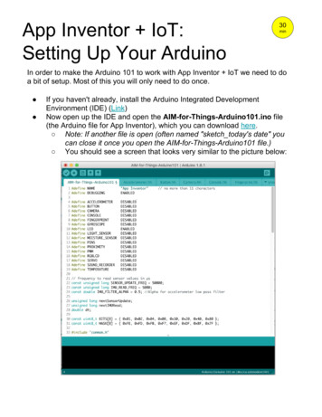
SIK Worksheets v. 1.0Name:Date:// Circuit 5, How the Circuits Work:Circuit 5Explanation:Schematic:The shift register in this circuit takes electricityfrom 5V on the Arduino. Pin # 2, # 3 and # 4 onthe Arduino supply a digital value. The latch andclock pins are used to allow data into the shiftregister. The shift register sets the eight outputpins to either HIGH or LOW depending on thevalues sent to it via the data pin. The LEDs areconnected to the circuit so electricity entersthrough the anode ( , or longer wire) and exitsthrough the cathode (-, or shorter wire) if theshift register pin is HIGH. The resistor dissipatescurrent so the LEDs do not draw current abovethe maximum rating and burn out. Finally theelectricity reaches ground, closing the circuitand allowing electricity to flow from powersource to ground.Data, Clock & LatchSignal Energy SourcesShift Register Energy SourcePin 4 Pin 3 Pin 2 5 volts 5Vdata1clock2latch6gndint data 2;int clock 3;int latch 4; 5V: Five Volt power source.Gnd: GroundGND(ground)(-)Electricity ends here7KEY:Direction of currentElectricity starts hereArduino Digital Pin # 2, # 3 and # 4: Signalpower source for data, clock and latch pins onshift register.330 Ohm Resistor: A resistor resists the currentflowing through the circuit. In this circuit theresistor reduces the current so the LEDdoes not burn out.35Code:LED: As in other diodes, current flows easilyfrom the side, or anode (longer wire), to the- side, or cathode (shorter wire), but not in thereversedirection. Lights up!resistor4Components:Shift register: Allows usage of eight output pinswith three input pins, a power and a ground.Link to datasheet.LED0int ledState 0;const int ON HIGH;const int OFF LOW;void setup() {pinMode(data, OUTPUT);pinMode(clock, OUTPUT);pinMode(latch, OUTPUT);}void loop(){for(int i 0; i 256; i ) {updateLEDs(i);delay(25);}}void updateLEDs(int value) {digitalWrite(latch, LOW);shiftOut(data, clock, MSBFIRST, value);digitalWrite(latch, HIGH);}Intro to Arduino //14
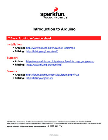
Intro to Arduino 60EXTTXRXLPWMPWMPOWER5V Gnd VinPWRICSPANALOG IN0 1 2 3 4 5www.arduino.ccArduinoPWM3 2 1 0 9 87 6 5 4 3 2 1 01 1 1 1DIGITALIJIHAREFGNDJFGFEHEDGCDC1B5A1BPWR SELAPWMPWMPWMRESET3V3TXRX1SIK Worksheets v. 1.0Name:Date:// Circuit 5, How the Circuits Work:
SIK Worksheets v. 1.0Name:Date:// Resistance:Resistance is an important concept when you are creating circuits.Resistance is the difficulty a current encounters when it passes through acomponent. Everything that electricity passes through provides somemeasure of resistance, wires, motors, sensors, even the human body!Measuring voltage, current and resistance are all done in different ways.To measure resistance you disconnect (turn off) your circuit and place bothmultimeter leads on either side of the portion of the circuit you wish tomeasure. For example: for measuring just a component you would place yourleads on the power and ground leads of the component. To measure theresistance of multiple components you leave them connected and place thepositive (red) multimeter lead closer to the disconnected power source and thenegative (black) multimeter lead closer to the ground. Sometimes you will wantto measure the resistance of input and output leads, but more often you will findyourself measuring resistance along the power to ground circuit. It isimportant to know how much resistance is present in components andcircuits for many reasons. Too much resistance and the current will nevertravel through the whole circuit, too little and the current may fry some ofyour components! But most importantly you can use resistance to choosethe path the current takes through your circuit.Hook up the circuit to the right using red LEDs. (Don’t hook up the power yet.)Measure the resistance of each of the possible paths the current can take frompower (5v) to ground. There are three possible paths. You will have to measureeach component separately and then add the resistance up for the total. You will
on the voltage of the Analog signal when compared to the Analog Reference signal the Arduino then assigns a numerical value to the signal somewhere between 0 (0%) and 1023 (100%). The digital system of the Arduino can then use this number in calculations and sketches. To receive Analog Input