Transcription
RASPBERRY PI MEGA-IO EXPANSION CARDwww.sequentmicrosystems.comUSER'S GUIDE VERSION 3.2GENERAL DESCRIPTION. 2BOARD LAYOUT . 3BLOCK DIAGRAM . 4COMPONENT DESCRIPTION . 5CONFIGURATION JUMPERS . 6MEGA-IO HEADER . 7RELAY HEADERS . 8POWER REQUIREMENTS . 9HARDWARE SPECIFICATIONS . 10MECHANICAL SPECIFICATIONS . 12SOFTWARE SETUP . 13MEGA-IO AD-ON CARDS. 15MEGA-IO SELF-TEST CARD . 15MEGA-IO LED-CARD . 17MEGA-IO BREAK-OUT CARD. 18DIN-RAIL KIT for RASPBERRY PI . 208-RELAY ADD-ON BOARD . 21MEGA-IO TESTING WITHOUT A TEST CARD . 221
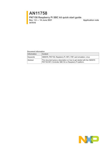
GENERAL DESCRIPTIONThe MEGA-IO is a stackable expansion card for Raspberry Pi B , 2, 3 and Zero. Two of the Raspberry Pi’sGPIO pins are used for I2C communication. Another pin is allocated for the interrupt handler, leaving 23GPIO pins available for the user. MEGA-IO adds the following I/O functions: Eight on-board relaysEight 12 bit A/D inputsEight optically isolated inputsOne 12 bit DAC OutputFour open collector outputsSix GPIO'sUp to four MEGA-IO cards can be stacked on top of a Raspberry Pi.Any of the inputs of the MEGA-IO can be configured as interrupt inputs.2
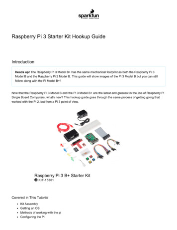
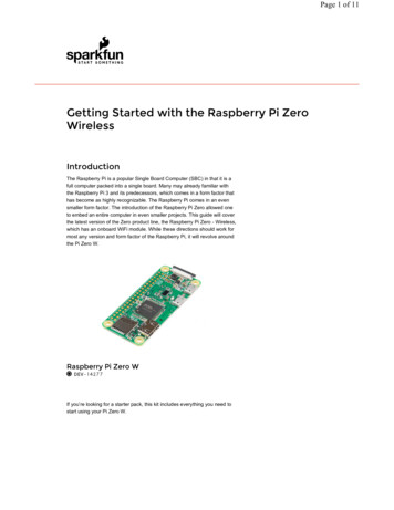
BOARD LAYOUT3
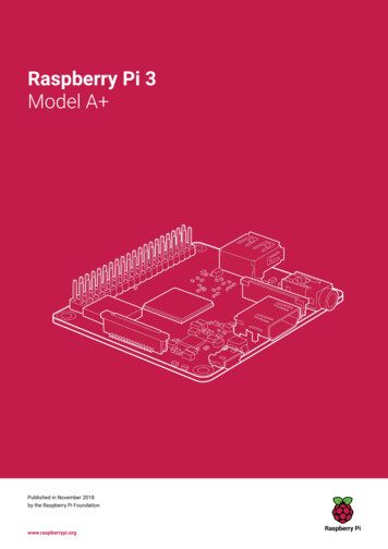
BLOCK DIAGRAM4
COMPONENT DESCRIPTIONThe top 40 pin header plugs into the Raspberry Pi GPIO header and passed through the pins to the nextMEGA-IO expansion card.The bottom 40 pin header is a right angle connector for I/O expansion.The eight Relays are numbered from upper left to lower right. Numbering the Relays is important toassociate them correctly with the Relay Headers and Relay LEDs. The Relays are SPST, with three outputpins labeled COM, NO and NC.The Relay LEDs are right angle, to permit visual inspection of the relays status when multiple cards arestacked.The Power LED in the upper right corner shows when power is applied to the board.5
CONFIGURATION JUMPERSThe 2x5 pin jumper installed in the upper right corner of the MEGA-IO card has the following functions:Position 1-2: Factory use only.Position 3: Processor reset.Position 4-5: Stack Level. These two jumpers permit addressing multiple MEGA-IO cards on the I2C bus.No jumpers need to be installed if only one card is present. If two or more cards are stacked up, the cardI2C address 0 - 3 is as follows:6
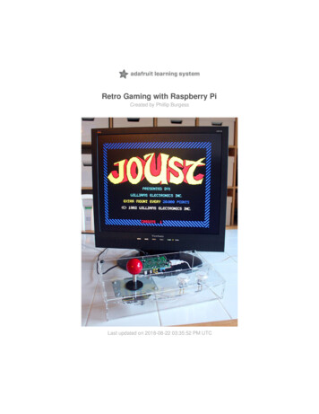
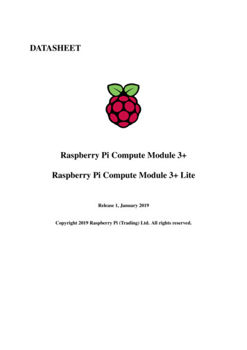
MEGA-IO HEADER7
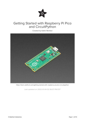
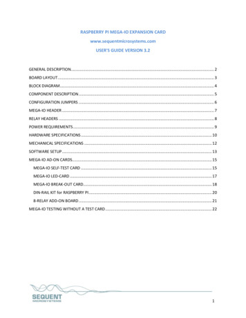
RELAY HEADERS8
POWER REQUIREMENTSThe Mega-IO card requires 5V power, supplied either from the Raspberry Pi expansion bus, or from itsown 2.1mm power jack. The on-board relays are connected to the 5V. A local 3.3V regulator powersthe rest of the circuits.Only one 5V source can be used to power both the Raspberry Pi and the Mega-IO card.Raspberry Pi 3 current consumption:250 mA @ 5VMega-IO current consumption:60 mA @ 5V (all relays OFF)800 mA @ 5V (all relays ON)The USB connector which powers the Raspberry Pi can supply maximum 1.5A.The jack which powers the Mega-IO card can supply 3A. We strongly recommend using this jack and a5V regulated power supply rated at 3A or higher.The Mega-IO card can be stacked up to four levels. A multi-stack configuration can be powered from anyof the cards. A four stack needs 500 mA for electronic circuits, leaving 2.5A for relays. With some marginof error, not more than 24 relays can be ON at the same time.In the rare event that your application uses four Mega-IO cards and requires that all relays be ON atthe same time, you need a power source that can supply minimum 4A. You also need to split thepower cable and feed the 5V through two Mega-IO cards.9
HARDWARE SPECIFICATIONSMICROCONTROLLER:STM8L151C3T6SIX GPIO pins: Operating voltage:CPU frequency:Touch sensing capability:Maximum input voltage:Series protection resistor:Output Low Level:Output High Level:3.3V16 MHzYes4V51 OhmsMaximum 0.45VMinimum 2.6VFOUR OPEN COLLECTOR OUTPUTS: Driver:Output Low Voltage:Max Pull Up Voltage:Maximum sink per channel:ESD:ULN2003F12FN-70.6V20V100mA @ 3.3V Logic Input, 140mA @ 5.0V Logic Input4kV HBM, 1kV CDMEIGHT 12 bit ADC: Sample rate:Input low pass filter:Up to 1 Msps0.22µF/51 ΩONE 12 bit DAC: Resistive load:Output impedance:Capacitive load:Settling time:Update rate:Minimum 5 KΩMaximum 10 KΩMaximum 50 pFMaximum 12 μsMaximum 1 Msps10
OPTOISOLATORS: Transceiver:LED current limit resistor:Input Forward Current:Input Reverse Voltage:Input Forward Voltage:Isolation Resistance:Isolation Voltage:TLP293-41 KΩTypical 5 mA, maximum 50 mA5V1.25V @ 10 mAMinimum 1012 ΩTypical 10,000 VRELAYS: SRD-05VDC-SL-C Relay maximum current/voltage:PCB maximum current/voltage:10A/250V5A/48VPOWER CONSUMPTION: 60 mA @ 5V (all relays OFF)800 mA @ 5V (all relays ON)11
MECHANICAL SPECIFICATIONS12
SOFTWARE SETUP1. Have your Raspberry Pi ready with the latest OS.2. Install the Wiring Pi library (many thanks to Gordon Henderson)3. Enable I2C communication: sudo raspi-config4. Install the megaio software from github.com: git clone https://github.com/alexburcea2877/megaio-rpi.git5. cd /home/pi/megaio-rpi6. /megaio-rpi sudo make install7. /megaio-rpi megaioThe program will respond with a list of available commands.Type "megaio -h" for online help.After installing the software, you can update it to the latest version with the commands:1. cd /home/pi/megaio-rpi13
2. /megaio-rpi git pull3. /megaio-rpi sudo make install14
MEGA-IO AD-ON CARDSMEGA-IO SELF-TEST CARDThe self-test card routs all the inputs to outputs, as shown in the following diagram:15
ADC7 analog input is used to test the analog output (DAC). The other seven analog inputs are connectedto resistor dividers:If the self-test card is present, the MEGA-IO can be tested using the command “megaio [0:3] test”. Thesoftware will cycle all relays until any key is pressed, then will report the status of all the inputs andoutputs.Self-test card top viewSelf-test card back view16
MEGA-IO LED-CARDThe LED card plugs into the Raspberry Pi expansion connector. Its main function is to show in top-viewthe status of the relays, but it can be used as a general purpose, 32 LED card to show the status of anyinput or output.Any LED can be turned on or off using the command “megaio led [1-32] on/off”17
MEGA-IO BREAK-OUT CARDThe Break-out card plugs into the MEGA-IO expansion connector and brings all the IO pins to screw-typeterminal blocks. It can be used also as a break-out card for the Raspberry Pi GPIO connector.Break-out card top viewBreak-out card back view18
Raspberry Pi with Break-out cardBreak-out cards for MEGA-IO and Raspberry Pi19
DIN-RAIL KIT for RASPBERRY PIThe DIN-Rail Kit permits mounting any Raspberry Pi on a DIN-Rail. It contains all the necessary screwsand stand-offs.20
8-RELAY ADD-ON BOARDThe 8-RELAY board is an inexpensive add-on board that can be mixed with the MEGA-IO card whenmore relays are needed, without adding more IO functions. The board is similar with the MEGA-IO, butall the IO functions have been removed in order to save cost. Up to four MEGA-IO and 8-RELAY cards canbe mixed in any configuration. A LED-CARD can be added to the stack as well.21
MEGA-IO TESTING WITHOUT A TEST CARDThe analog and digital I/O's of the MEGA-IO card can be self-tested without a self test card by running aone wire jumper between one input and one output. The I/O's under test need to be disconnected fromany external sources. The following commands are available for one wire self testing:OPEN COLLECTOR OUTPUT TO OPTO-ISOLATED INPUT:Command:megaio [0:3] test-opto-oc [1:8] [1:4]Example:megaio 0 test-opto-oc 1 2This command requires a jumper from 5V (pin 2) to VEXT1 (pin 4) to power the OPTO-INPUTS, andanother jumper from OPTO1 (pin 3) to OC2 (pin 32). The software will set the output low and high andcheck the values on the input.DIGITAL INPUT TO DIGITAL OUTPUT:Command:megaio [0:3] test-io [1:6] [1:6]Example:megaio 0 test-io 2 5This command requires a jumper from IO2 (pin 27) to IO5 (pin 23).ANALOG I/O self test command:Example:megaio [0:3] test-dac-adc [1:8]megaio 0 test-dac-adc1This command requires a jumper from DAC (pin 7) to ADC1 (pin 21). The software will set the DACoutput to 0, 25%, 50% and 100% of the full scale, and measure the corresponding values on the ADCinput.The MEGA-IO card can also be tested using its own IO Commans. Here are examples for testing all IOfunctions:1) IO Test- Connect pin 27 to pin 28 (IO1 to IO2)- Set IO1 as output : pi@raspberrypi: megaio 0 iodwrite 1 0- Read IO2 pin : pi@raspberrypi: megaio 0 ioread 2 (Response should be 0)- Write IO1 pin: pi@raspberrypi: megaio 0 iowrite 1 122
- Read IO2 pin : pi@raspberrypi: megaio 0 ioread 2 (Response should be 1)2) DAC - ADC test- Connect pin 7 to pin 11 (DAC to ADC channel 7)- Write DAC value 0: pi@raspberrypi: megaio 0 awrite 0 (0V)- Read ADC channel 7: pi@raspberrypi: megaio 0 aread 7 (Response should be less than 150 )- Write DAC value 2000: pi@raspberrypi: megaio 0 awrite 2000 (1.6V)- Read ADC channel 7: pi@raspberrypi: megaio 0 aread 7 (Response should be 2000 /-75 )- Write DAC value 4095: pi@raspberrypi: megaio 0 awrite 4095 (3.3V)- Read ADC channel 7: pi@raspberrypi: megaio 0 aread 7 (Response should be more than 3950)3) Open collector output - Opto-coupled input- Connect pin 2 to pin 4 (5V to Opto 5V external)- Connect pin 3 to pin 33 (Opto channel 1 to open collector channel 1)- Set OFF OC channel 1 : pi@raspberrypi: megaio 0 ocwrite 1 0- Read opto channel 1: pi@raspberrypi: megaio 0 optread 1 ( Response should be 0)- Set ON OC channel 1 : pi@raspberrypi: megaio 0 ocwrite 1 1- Read opto channel 1: pi@raspberrypi: megaio 0 optread 1 ( Response should be 1)23
The MEGA-IO is a stackable expansion card for Raspberry Pi B , 2, 3 and Zero. Two of the Raspberry Pi’s GPIO pins are used for I2C communication. Another pin is allocated for the interrupt handler, leaving 23 GPIO pins available for the user. MEGA-IO adds the following I/O functions: Eight on-board relays Eight 12 bit A/D inputs