Transcription
DATASHEETRaspberry Pi Compute Module 3 Raspberry Pi Compute Module 3 LiteRelease 1, January 2019Copyright 2019 Raspberry Pi (Trading) Ltd. All rights reserved.
Compute Module 3 DatasheetCopyright Raspberry Pi (Trading) Ltd. 2019Table 1: Release HistoryReleaseDateDescription128/01/2019First releaseThe latest release of this document can be found at https://www.raspberrypi.org1Release 2
Compute Module 3 DatasheetCopyright Raspberry Pi (Trading) Ltd. 2019Contents1Introduction52Features2.1 Hardware . . . . . . . . . . . . . . . . . . . . . . . . . . . . . . . . . . . . . . . . . .2.2 Peripherals . . . . . . . . . . . . . . . . . . . . . . . . . . . . . . . . . . . . . . . . .2.3 Software . . . . . . . . . . . . . . . . . . . . . . . . . . . . . . . . . . . . . . . . . . .66663Block Diagram74Mechanical Specification85Pin Assignments96Electrical Specification7Power Supplies137.1 Supply Sequencing . . . . . . . . . . . . . . . . . . . . . . . . . . . . . . . . . . . . . 147.2 Power Requirements . . . . . . . . . . . . . . . . . . . . . . . . . . . . . . . . . . . . 148Booting149Peripherals9.1 GPIO . . . . . . . . . . . . . . . . . . . .9.1.1 GPIO Alternate Functions . . . . .9.1.2 Secondary Memory Interface (SMI)9.1.3 Display Parallel Interface (DPI) . .9.1.4 SD/SDIO Interface . . . . . . . . .9.2 CSI (MIPI Serial Camera) . . . . . . . . .9.3 DSI (MIPI Serial Display) . . . . . . . . .9.4 USB . . . . . . . . . . . . . . . . . . . . .9.5 HDMI . . . . . . . . . . . . . . . . . . . .9.6 Composite (TV Out) . . . . . . . . . . . .151516171718181818181911.10 Thermals1910.1 Temperature Range . . . . . . . . . . . . . . . . . . . . . . . . . . . . . . . . . . . . . 1911 Availability1912 Support192Release 2
Compute Module 3 DatasheetCopyright Raspberry Pi (Trading) Ltd. 2019List of Figures123CM3 Block Diagram . . . . . . . . . . . . . . . . . . . . . . . . . . . . . . . . . . . 7CM3 Mechanical Dimensions . . . . . . . . . . . . . . . . . . . . . . . . . . . . . . . 8Digital IO Characteristics . . . . . . . . . . . . . . . . . . . . . . . . . . . . . . . . . . 133Release 2
Compute Module 3 DatasheetCopyright Raspberry Pi (Trading) Ltd. 2019List of Tables12345678910Release History . . . . . . . . . . . . . . . . . .Compute Module 3 SODIMM Connector PinoutPin Functions . . . . . . . . . . . . . . . . . . .Absolute Maximum Ratings . . . . . . . . . . .DC Characteristics . . . . . . . . . . . . . . . .Digital I/O Pin AC Characteristics . . . . . . . .Power Supply Operating Ranges . . . . . . . . .Mimimum Power Supply Requirements . . . . .GPIO Bank0 Alternate Functions . . . . . . . . .GPIO Bank1 Alternate Functions . . . . . . . . .4.191011121213141617Release 2
Compute Module 3 DatasheetCopyright Raspberry Pi (Trading) Ltd. 20191IntroductionThe Raspberry Pi Compute Module 3 (CM3 ) is a range of DDR2-SODIMM-mechanically-compatibleSystem on Modules (SoMs) containing processor, memory, eMMC Flash (on non-Lite variants) andsupporting power circuitry. These modules allow a designer to leverage the Raspberry Pi hardware andsoftware stack in their own custom systems and form factors. In addition these modules have extra IOinterfaces over and above what is available on the Raspberry Pi model A/B boards, opening up moreoptions for the designer.The CM3 contains a BCM2837B0 processor (as used on the Raspberry Pi 3B ), 1Gbyte LPDDR2RAM and eMMC Flash. The CM3 is currently available in 4 variants, CM3 /8GB, CM3 /16GB,CM3 /32GB and CM3 Lite, which have 8, 16 and 32 Gigabytes of eMMC Flash, or no eMMC Flash,respectively.The CM3 Lite product is the same as CM3 except the eMMC Flash is not fitted, and the SD/eMMCinterface pins are available for the user to connect their own SD/eMMC device.Note that the CM3 is electrically identical and, with the exception of higher CPU z-height, physicallyidentical to the legacy CM3 products.CM3 modules require a software/firmware image dated November 2018 or newer to function correctly.5Release 2
Compute Module 3 DatasheetCopyright Raspberry Pi (Trading) Ltd. 201922.1FeaturesHardware Low cost Low power High availability High reliability– Tested over millions of Raspberry Pis Produced to date– Module IO pins have 15 micro-inch hard gold plating over 2.5 micron Nickel2.2Peripherals 48x GPIO 2x I2C 2x SPI 2x UART 2x SD/SDIO 1x HDMI 1.3a 1x USB2 HOST/OTG 1x DPI (Parallel RGB Display) 1x NAND interface (SMI) 1x 4-lane CSI Camera Interface (up to 1Gbps per lane) 1x 2-lane CSI Camera Interface (up to 1Gbps per lane) 1x 4-lane DSI Display Interface (up to 1Gbps per lane) 1x 2-lane DSI Display Interface (up to 1Gbps per lane)2.3Software ARMv8 Instruction Set Mature and stable Linux software stack– Latest Linux Kernel support– Many drivers upstreamed– Stable and well supported userland– Full availability of GPU functions using standard APIs6Release 2
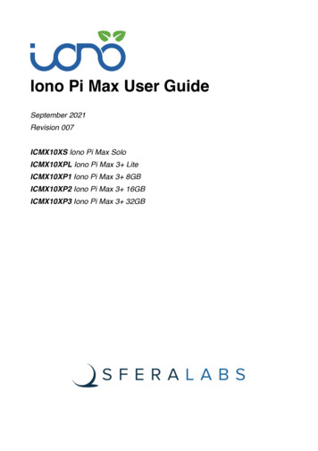
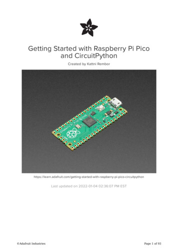
Compute Module 3 DatasheetCopyright Raspberry Pi (Trading) Ltd. 2019Block DiagramEMMC EN N 1V8IO ExpanderHDMI HPD N 1V8VBATCore SMPS3V31V8VDACTVDACVDD GPIO0-27GPIO[0:27]VDD GPIO28-45GPIO[28:45]200 Pin SODIMM Connector3CSI CAM0CSI CAM1DSI DISP0DSI DISP1CMCHOKESHDMI CEC, DDCTVDACBCM2837B0GPIOBANK0GPIOBANK11GByte LPDDR22 Lane CSI Camera4 Lane CSI Camera2 Lane DSI Display4 Lane DSI DisplayHDMI TMDSCLOCK & DATA4GByte eMMC(CM3 only)HDMI CEC & I2CUSBUSB OTGIDUSB2JTAG3V3SD I/O VOLTAGESD CMD, DxSD CLKRUNRUN3V3EMMC DISABLE NSDX CLK (CM3 Lite only)1V8CM3 eMMC I/OVoltage fixed at1V8CM3 LiteSD I/O Voltagesupplied fromSDX VDDSDX CMD, Dx (CM3 Lite only)SDX VDD (CM3 Lite only)Figure 1: CM3 Block Diagram7Release 2
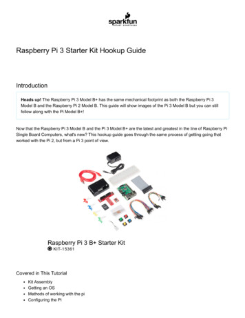
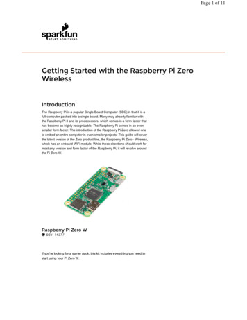
Compute Module 3 DatasheetCopyright Raspberry Pi (Trading) Ltd. 20194Mechanical SpecificationThe CM3 modules conform to JEDEC MO-224 mechanical specification for 200 pin DDR2 (1.8V)SODIMM modules and therefore should work with the many DDR2 SODIMM sockets available on themarket. (Please note that the pinout of the Compute Module is not the same as a DDR2 SODIMMmodule; they are not electrically compatible.)The SODIMM form factor was chosen as a way to provide the 200 pin connections using a standard,readily available and low cost connector compatible with low cost PCB manufacture.The maximum component height on the underside of the Compute Module is 1.2mm.The maximum component height on the top side of the Compute Module is 2.5mm.The Compute Module PCB thickness is 1.0mm /- 0.1mm.Note that the location and arrangement of components on the Compute Module may change slightlyover time due to revisions for cost and manufacturing considerations; however, maximum componentheights and PCB thickness will be kept as specified.Figure 2 gives the CM3 mechanical dimensions.Figure 2: CM3 Mechanical Dimensions8Release 2
Compute Module 3 DatasheetCopyright Raspberry Pi (Trading) Ltd. 20195Pin AssignmentsCM3 CM3 6GPIO7GNDGPIO8GPIO9GNDGPIO10GPIO11GNDGPIO0-27 121416182022242628303234363840CM3 CM3 LiteEMMC DISABLE NNCSDX VDDNCSDX VDDGNDNCSDX CLKNCSDX CMDGNDNCSDX D0NCSDX D1GNDNCSDX D2NCSDX D3GNDGPIO28GPIO29GNDGPIO30GPIO31GNDGPIO0-27 92194196198200GPIO28-45 44GPIO45GNDHDMI HPD N 1V8EMMC EN N 1V8GNDDSI1 DP0DSI1 DN0GNDDSI1 CPDSI1 CNGNDDSI1 DP3DSI1 DN3GNDDSI1 DP2DSI1 DN2GNDDSI1 DP1DSI1 DN1GNDNCNCNCNCNCGNDCAM0 DP0CAM0 DN0GNDCAM0 CPCAM0 CNGNDCAM0 DP1CAM0 DN1GNDNCNCNCNCNCGNDTVDACUSB OTGIDGNDVC TRST NVC TDIVC TMSVC TDOVC TCKGND1V81V8GNDVDAC3V33V3GNDVBATVBATKEYGPIO28-45 83GND85GPIO2687GPIO2789GND91DSI0 DN193DSI0 DP195GND97DSI0 DN099DSI0 DP0101GND103DSI0 CN105DSI0 CP107GND109HDMI CLK N111HDMI CLK P113GND115HDMI D0 N117HDMI D0 P119GND121HDMI D1 N123HDMI D1 P125GND127HDMI D2 N129HDMI D2 P131GND133CAM1 DP3135CAM1 DN3137GND139CAM1 DP2141CAM1 DN2143GND145CAM1 CP147CAM1 CN149GND151CAM1 DP1153CAM1 DN1155GND157CAM1 DP0159CAM1 DN0161GND163USB DP165USB DM167GND169HDMI CEC171HDMI SDA173HDMI SCL175RUN177VDD CORE (DO NOT 3193GND195VBAT197VBAT199Table 2: Compute Module 3 SODIMM Connector PinoutTable 2 gives the Compute Module 3 pinout and Table 3 gives the pin functions.9Release 2
Compute Module 3 DatasheetCopyright Raspberry Pi (Trading) Ltd. 2019Pin NameDIRVoltage RefPDNa StateIf UnusedDescription/NotesRUN and Boot Control (see text for usage guide)RUNEMMC DISABLE NEMMC EN N 1V8IIO3V3b3V3b1V8Pull HighPull HighPull HighLeave openLeave openLeave openHas internal 10k pull upHas internal 10k pull upHas internal 2k2 pull upI/OI/OGPIO0-27 VDDGPIO28-45 VDDPull or Hi-ZcPull or Hi-ZcLeave openLeave openGPIO Bank 0GPIO Bank 1OI/OI/OSDX VDDSDX VDDSDX VDDPull HighPull HighPull HighLeave openLeave openLeave openPrimary SD interface CLKPrimary SD interface CMDPrimary SD interface DATAI/OI3V3ZLeave openTie to GNDSerial interfaceOTG pin detectI/OI/OI/OOOI3V3b3V3b3V31V8ZfZfZZZPull HighLeave openLeave openLeave openLeave openLeave openLeave openDDC Clock (5.5V tolerant)DDC Data (5.5V tolerant)CEC (has internal 27k pull up)HDMI serial clockHDMI serial dataHDMI hotplug detect-ZZLeave openLeave openSerial clockSerial data-ZZLeave openLeave openSerial clockSerial dataZZLeave openLeave openSerial clockSerial dataGPIOGPIO[27:0]GPIO[45:28]Primary SD Interfaced,eSDX CLKSDX CMDSDX DxUSB InterfaceUSB DxUSB OTGIDHDMI D N 1V8CAM0 (CSI0) 2-lane InterfaceCAM0 CxCAM0 DxIICAM1 (CSI1) 4-lane InterfaceCAM1 CxCAM1 DxIIDSI0 (Display 0) 2-lane InterfaceDSI0 CxDSI0 DxOO-DSI1 (Display 1) 4-lane InterfaceDSI1 CxDSI1 DxOO-ZZLeave openLeave openSerial clockSerial dataO-ZLeave openComposite video DAC outputIIIIO3V33V33V33V33V3ZZZZOLeave openLeave openLeave openLeave openLeave openHas internal 50k pull upHas internal 50k pull upHas internal 50k pull upHas internal 50k pull upHas internal 50k pull upTV OutTVDACJTAG InterfaceTMSTRST NTCKTDITDOaThe PDN column indicates power-down state (when RUN pin LOW)Must be driven by an open-collector driverc GPIO have software enabled pulls which keep state over power-downd Only available on Lite variantse The CM will always try to boot from this interface firstf Requires external pull-up resistor to 5V as per HDMI specbTable 3: Pin Functions10Release 2
Compute Module 3 DatasheetCopyright Raspberry Pi (Trading) Ltd. 20196Electrical SpecificationCaution! Stresses above those listed in Table 4 may cause permanent damage to the device. This isa stress rating only; functional operation of the device under these or any other conditions above thoselisted in the operational sections of this specification is not implied. Exposure to absolute maximumrating conditions for extended periods may affect device ore SMPS Supply-0.56.0V3V33V3 Supply Voltage-0.54.10V1V81V8 Supply Voltage-0.52.10VVDACTV DAC Supply-0.54.10VGPIO0-27 VDDGPIO0-27 I/O Supply Voltage-0.54.10VGPIO28-45 VDDGPIO28-45 I/O Supply Voltage-0.54.10VSDX VDDPrimary SD/eMMC Supply Voltage-0.54.10VTable 4: Absolute Maximum RatingsDC Characteristics are defined in Table 511Release 2
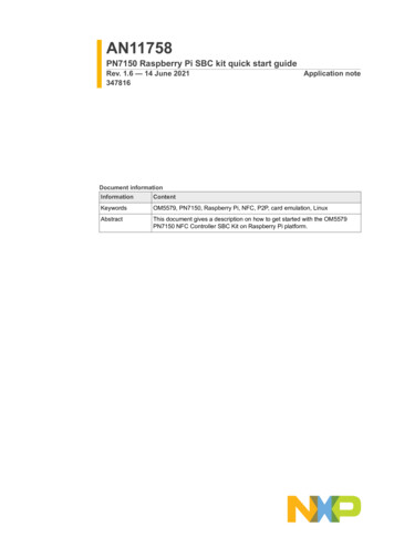
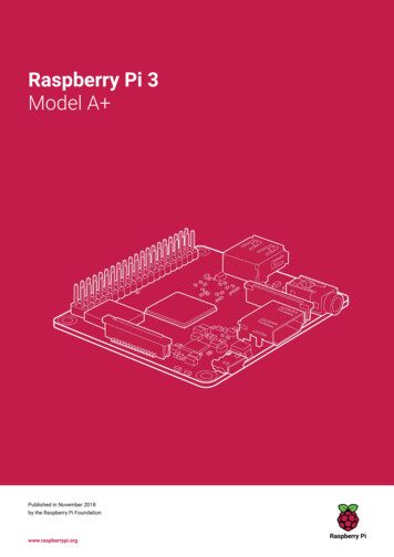
Compute Module 3 DatasheetCopyright Raspberry Pi (Trading) Ltd. lMaximumUnitVDD IO 1.8VVDD IO 2.7VVDD IO 3.3V--0.60.80.9VVVVILInput lowVIHInput high voltageaVDD IO 1.8VVDD IO 2.7VVDD IO 3.3V1.01.31.6--VVVIILInput leakage currentTA 85 C--5µACINInput capacitance--5-pFVOLOutput low voltagebVDD IO 1.8V, IOL -2mAVDD IO 2.7V, IOL -2mAVDD IO 3.3V, IOL -2mA--0.20.150.14VVVVOHOutput high voltagebVDD IO 1.8V, IOH 2mAVDD IO 2.7V, IOH 2mAVDD IO 3.3V, IOH 2mA1.62.53.0--VVVIOLOutput low currentcVDD IO 1.8V, VO 0.4VVDD IO 2.7V, VO 0.4VVDD IO 3.3V, VO 0.4V121718--mAmAmAIOHOutput high currentcVDD IO 1.8V, VO 1.4VVDD IO 2.7V, VO 2.3VVDD IO 3.3V, VO 2.3V101617--mAmAmARP UPullup resistor-50-65kΩRP DPulldown resistor-50-65kΩaHysteresis enabledDefault drive strength (8mA)c Maximum drive strength (16mA)bTable 5: DC CharacteristicsAC Characteristics are defined in Table 6 and Fig. 3.Pin l outputstrise10-90% rise timea-1.6-nsDigital outputstf all90-10% fall timea-1.7-nsGPCLKtJOSCOscillator-derived GPCLKcycle-cycle jitter (RMS)--20psGPCLKtJP LLPLL-derived GPCLKcycle-cycle jitter (RMS)--48psaDefault drive strength, CL 5pF, VDD IOx 3.3VTable 6: Digital I/O Pin AC Characteristics12Release 2
Compute Module 3 DatasheetCopyright Raspberry Pi (Trading) Ltd. 2019tfalltriseDIGITALOUTPUTFigure 3: Digital IO Characteristics7Power SuppliesThe Compute Module 3 has six separate supplies that must be present and powered at all times; youcannot leave any of them unpowered, even if a specific interface or GPIO bank is unused. The sixsupplies are as follows:1. VBAT is used to power the BCM2837 processor core. It feeds the SMPS that generates the chipcore voltage.2. 3V3 powers various BCM2837 PHYs, IO and the eMMC Flash.3. 1V8 powers various BCM2837 PHYs, IO and SDRAM.4. VDAC powers the composite (TV-out) DAC.5. GPIO0-27 VREF powers the GPIO 0-27 IO bank.6. GPIO28-45 VREF powers the GPIO 28-45 IO Core SMPS Supply2.5-5.0 5%V3V33V3 Supply Voltage3.3 - 5%3.33.3 5%V1V81V8 Supply Voltage1.8 - 5%1.81.8 5%VVDACTV DAC Supplya2.5 - 5%2.83.3 5%VGPIO0-27 VDDGPIO0-27 I/O Supply Voltage1.8 - 5%-3.3 5%VGPIO28-45 VDDGPIO28-45 I/O Supply Voltage1.8 - 5%-3.3 5%VSDX VDDPrimary SD/eMMC Supply Voltage1.8 - 5%-3.3 5%VaRequires a clean 2.5-2.8V supply if TV DAC is used, else connect to 3V3Table 7: Power Supply Operating Ranges13Release 2
Compute Module 3 DatasheetCopyright Raspberry Pi (Trading) Ltd. 20197.1Supply SequencingSupplies should be staggered so that the highest voltage comes up first, then the remaining voltagesin descending order. This is to avoid forward biasing internal (on-chip) diodes between supplies, andcausing latch-up. Alternatively supplies can be synchronised to come up at exactly the same time aslong as at no point a lower voltage supply rail voltage exceeds a higher voltage supply rail voltage.7.2Power RequirementsExact power requirements will be heavily dependent upon the individual use case. If an on-chip subsystem is unused, it is usually in a low power state or completely turned off. For instance, if your applicationdoes not use 3D graphics then a large part of the core digital logic will never turn on and need power.This is also the case for camera and display interfaces, HDMI, USB interfaces, video encoders anddecoders, and so on.Powerchain design is critical for stable and reliable operation of the Compute Module 3 . We stronglyrecommend that designers spend time measuring and verifying power requirements for their particularuse case and application, as well as paying careful attention to power supply sequencing and maximumsupply voltage tolerance.Table 8 specifies the recommended minimum power supply outputs required to power the ComputeModule 3 .SupplyMinimum RequirementUnitVBAT (CM1)2000amWVBAT (CM3,3L)3500amW3V3250mA1V8250mAVDAC25mAGPIO0-27 VDD50bmAGPIO28-45 VDD50bmASDX VDD50bmAabRecommended minimum. Actual power drawn is very dependent on use-caseEach GPIO can supply up to 16mA, aggregate current per bank must not exceed 50mATable 8: Mimimum Power Supply Requirements8BootingThe eMMC Flash device on CM3 is directly connected to the primary BCM2837 SD/eMMC interface.These connections are not accessible on the module pins. On CM3 Lite this SD interface is availableon the SDX pins.14Release 2
Compute Module 3 DatasheetCopyright Raspberry Pi (Trading) Ltd. 2019When initially powered on, or after the RUN pin has been held low and then released, the BCM2837will try to access the primary SD/eMMC interface. It will then look for a file called bootcode.bin on theprimary partition (which must be FAT) to start booting the system. If it cannot access the SD/eMMCdevice or the boot code cannot be found, it will fall back to waiting for boot code to be written to it overUSB; in other words, its USB port is in slave mode waiting to accept boot code from a suitable host.A USB boot tool is available on Github which allows a host PC running Linux to write the BCM2837boot code over USB to the module. That boot code then runs and provides access to the SD/eMMC as aUSB mass storage device, which can then be read and written using the host PC. Note that a Raspberry Pican be used as the host machine. For those using Windows a precompiled and packeged tool is available.For more information see here.The Compute Module has a pin called EMMC DISABLE N which when shorted to GND will disablethe SD/eMMC interface (by physically disconnecting the SD CMD pin), forcing BCM2837 to boot fromUSB. Note that when the eMMC is disabled in this way, it takes a couple of seconds from powering upfor the processor to stop attempting to talk to the SD/eMMC device and fall back to booting from USB.Note that once booted over USB, BCM2837 needs to re-enable the SD/eMMC device (by releasingEMMC DISABLE N) to allow access to it as mass storage. It expects to be able to do this by drivingthe EMMC EN N 1V8 pin LOW, which at boot is initially an input with a pull up to 1V8. If an end userwishes to add the ability to access the SD/eMMC over USB in their product, similar circuitry to thatused on the Compute Module IO Board to enable/disable the USB boot and SD/eMMC must be used;that is, EMMC DISABLE N pulled low via MOSFET(s) and released again by MOSFET, with the gatecontrolled by EMMC EN N 1V8. Ensure you use MOSFETs suitable for switching at 1.8V (i.e. usea device with gate threshold voltage, Vt, suitable for 1.8V switching).99.1PeripheralsGPIOBCM2837 has in total 54 GPIO lines in 3 separate voltage banks. All GPIO pins have at least twoalternative functions within the SoC. When not used for the alternate peripheral function, each GPIOpin may be set as an input (optionally as an interrupt) or an output. The alternate functions are usuallyperipheral I/Os, and most peripherals appear twice to allow flexibility on the choice of I/O voltage.GPIO bank2 is used on the module to connect to the eMMC device and for an on-board I2C bus (to talkto the core SMPS and control the special function pins). On CM3 Lite most of bank2 is exposed toallow a user to connect their choice of SD card or eMMC device (if required).Bank0 and 1 GPIOs are available for general use. GPIO0 to GPIO27 are bank0 and GPIO28-45 makeup bank1. GPIO0-27 VDD is the power supply for bank0 and GPIO28-45 VDD is the power supply forbank1. SDX VDD is the supply for bank2 on CM3 Lite. These supplies can be in the range 1.8V-3.3V(see Table 7) and are not optional; each bank must be powered, even when none of the GPIOs for thatbank are used.Note that the HDMI HPD N 1V8 and EMMC EN N 1V8 pins are 1.8V IO and are used for specialfunctions (HDMI hot plug detect and boot control respectively). Please do not use these pins forany other purpose, as the software for the module will always expect these pins to have thesespecial functions. If they are unused please leave them unconnected.15Release 2
Compute Module 3 DatasheetCopyright Raspberry Pi (Trading) Ltd. 2019All GPIOs except GPIO28, 29, 44 and 45 have weak in-pad pull-ups or pull-downs enabled when thedevice is powered on. It is recommended to add off-chip pulls to GPIO28, 29, 44 and 45 to make surethey never float during power on and initial boot.9.1.1GPIO Alternate ighSDA0SA5PCLK---1HighSCL0SA4DE---2HighSDA1SA3LCD VSYNC---3HighSCL1SA2LCD HSYNC---4HighGPCLK0SA1DPI D0--ARM TDI5HighGPCLK1SA0DPI D1--ARM TDO6HighGPCLK2SOE NDPI D2--ARM RTCK7HighSPI0 CE1 NSWE NDPI D3---8HighSPI0 CE0 NSD0DPI D4---9LowSPI0 MISOSD1DPI D5---10LowSPI0 MOSISD2DPI D6---11LowSPI0 SCLKSD3DPI D7---12LowPWM0SD4DPI D8--ARM TMS13LowPWM1SD5DPI D9--ARM TCK14LowTXD0SD6DPI D10--TXD115LowRXD0SD7DPI D11--RXD116LowFL0SD8DPI D12CTS0SPI1 CE2 NCTS117LowFL1SD9DPI D13RTS0SPI1 CE1 NRTS118LowPCM CLKSD10DPI D14-SPI1 CE0 NPWM019LowPCM FSSD11DPI D15-SPI1 MISOPWM120LowPCM DINSD12DPI D16-SPI1 MOSIGPCLK021LowPCM DOUTSD13DPI D17-SPI1 SCLKGPCLK122LowSD0 CLKSD14DPI D18SD1 CLKARM TRST-23LowSD0 CMDSD15DPI D19SD1 CMDARM RTCK-24LowSD0 DAT0SD16DPI D20SD1 DAT0ARM TDO-25LowSD0 DAT1SD17DPI D21SD1 DAT1ARM TCK-26LowSD0 DAT2TE0DPI D22SD1 DAT2ARM TDI-27LowSD0 DAT3TE1DPI D23SD1 DAT3ARM TMS-Table 9: GPIO Bank0 Alternate Functions16Release 2
Compute Module 3 DatasheetCopyright Raspberry Pi (Trading) Ltd. DA0SA5PCM CLKFL0--29NoneSCL0SA4PCM FSFL1--30LowTE0SA3PCM DINCTS0-CTS131LowFL0SA2PCM DOUTRTS0-RTS132LowGPCLK0SA1RING E NTE2SD1 CLK--35HighSPI0 CE1 NSWE N-SD1 CMD--36HighSPI0 CE0 NSD0TXD0SD1 DAT0--37LowSPI0 MISOSD1RXD0SD1 DAT1--38LowSPI0 MOSISD2RTS0SD1 DAT2--39LowSPI0 SCLKSD3CTS0SD1 DAT3--40LowPWM0SD4-SD1 DAT4SPI2 MISOTXD141LowPWM1SD5TE0SD1 DAT5SPI2 MOSIRXD142LowGPCLK1SD6TE1SD1 DAT6SPI2 SCLKRTS143LowGPCLK2SD7TE2SD1 DAT7SPI2 CE0 NCTS144NoneGPCLK1SDA0SDA1TE0SPI2 CE1 N-45NonePWM1SCL0SCL1TE1SPI2 CE2 N-Table 10: GPIO Bank1 Alternate FunctionsTable 9 and Table 10 detail the default pin pull state and available alternate GPIO functions. Most ofthese alternate peripheral functions are described in detail in the Broadcom Peripherals Specificationdocument and have Linux drivers available.9.1.2Secondary Memory Interface (SMI)The SMI peripheral is an asynchronous NAND type bus supporting Intel mode80 type transfers at 8 or16 bit widths and available in the ALT1 positions on GPIO banks 0 and 1 (see Table 9 and Table 10). Itis not publicly documented in the Broadcom Peripherals Specification but a Linux driver is available inthe Raspberry Pi Github Linux repository (bcm2835 smi.c in linux/drivers/misc).9.1.3Display Parallel Interface (DPI)A standard parallel RGB (DPI) interface is available on bank 0 GPIOs. This up-to-24-bit parallel interface can support a secondary display. Again this interface is not documented in the Broadcom Peripherals Specification but documentation can be found here.17Release 2
Compute Module 3 DatasheetCopyright Raspberry Pi (Trading) Ltd. 20199.1.4SD/SDIO InterfaceThe BCM283x supports two SD card interfaces, SD0 and SD1.The first (SD0) is a proprietary Broadcom controller that does not support SDIO and is the primaryinterface used to boot and talk to the eMMC or SDX x signals.The second interface (SD1) is standards compliant and can interface to SD, SDIO and eMMC devices;for example on a Raspberry Pi 3 B it is used to talk to the on-board CYW43455 WiFi device in SDIOmode.Both interfaces can support speeds up to 50MHz single ended (SD High Speed Mode).9.2CSI (MIPI Serial Camera)Currently the CSI interface is not openly documented and only CSI camera sensors supported by theofficial Raspberry Pi firmware will work with this interface. Supported sensors are the OmniVisionOV5647 and Sony IMX219.It is recommended to attach other cameras via USB.9.3DSI (MIPI Serial Display)Currently the DSI interface is not openly documented and only DSI displays supported by the officialRaspberry Pi firmware will work with this interface.Displays can also be added via the parallel DPI interface which is available as a GPIO alternate function- see Table 9 and Section 9.1.39.4USBThe BCM2837 USB port is On-The-Go (OTG) capable. If using either as a fixed slave or fixed master,please tie the USB OTGID pin to ground.The USB port (Pins USB DP and USB DM) must be routed as 90 ohm differential PCB traces.Note that the port is capable of being used as a true OTG port however there is no official documentation.Some users have had success making this work.9.5HDMIBCM283x supports HDMI V1.3a.It is recommended that users follow a similar arrangement to the Compute Module IO Board circuitryfor HDMI output.The HDMI CK P/N (clock) and D0-D2 P/N (data) pins must each be routed as matched length 100ohm differential PCB traces. It is also important to make sure that each differential pair is closely phasematched. Finally, keep HDMI traces well away from other noise sources and as short as possible.Failure to observe these design rules is likely to result in EMC failure.18Release 2
Compute Module 3 DatasheetCopyright Raspberry Pi (Trading) Ltd. 20199.6Composite (TV Out)The TVDAC pin can be used to output composite video (PAL or NTSC). Please route this signal awayfrom noise sources and use a 75 ohm PCB trace.Note that the TV DAC is powered from the VDAC supply which must be a clean supply of 2.5-2.8V. Itis recommended users generate this supply from 3V3 using a low noise LDO.If the TVDAC output is not used VDAC can be connected to 3V3, but it must be powered even if theTV-out functionality is unused.10ThermalsThe BCM2837 SoC employs DVFS (Dynamic Voltage and Frequency Scaling) on the core voltage.When the processor is idle (low CPU utilisation), it will reduce the core frequency and voltage to reducecurrent draw and heat output. When the core utilisation exceeds a certain threshold the core votlageis increased and the core frequency is boosted to the maximum working frerquency of 1.2GHz. Thevoltage and frequency are throttled back when the CPU load reduces back to an ’idle’ level OR whenthe silicon temperature as mesured by the on-chip temperature sensor exceeds 80C (thermal throttling).A designer must pay careful attention to the thermal design of products using the CM3 so thatperformance is not artificially curtailed due to the processor thermal throttling, as the Quad ARMcomplex in the BCM2837 can generate significant heat output under load.10.1Temperature RangeThe operating temperature range of the module is set by the lowest maximum and highest minimum ofany of the components used.The eMMC and LPDDR2 have the narrowest range, these are rated for -25 to 80 degrees Celsius.Therefore the nominal range for the CM3 and CM3 Lite is -25C to 80C.However, this range is the maximum for the silicon die; therefore, users would have to take into accountthe heat generated when in use and make sure this does not cause the temperature to exceed 80 degreesCelsius.11AvailabilityRaspberry Pi guarantee availability of CM3 and CM3 Lite until at least January 2026.12SupportFor support please see the hardware documentation section of the Raspberry Pi website and post questions to the Raspberry Pi forum.19Release 2
The Raspberry Pi Compute Module 3 (CM3 ) is a range of DDR2-SODIMM-mechanically-compatible System on Modules (SoMs) containing processor, memory, eMMC Flash (on non-Lite variants) and supporting power circuitry. These modules allow a designer to leverage the Raspberry Pi hardware and sof