Transcription
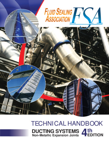
TECHNICAL HANDBOOKDUCTING SYSTEMSNon-Metallic Expansion Joints4thEDITION
AcknowledgementsThe Fluid Sealing Association (FSA) is pleased toacknowledge the member companies and individualswho served on the Technical Committee of the DuctingSystems Non-Metallic Expansion Joints division, formaking a particularly significant contribution to thispublication.The FSA is also pleased to acknowledge the cooperation of the European Sealing Association (ESA).This document is the copyright 2010 of theFluid Sealing Association (FSA).All rights reserved.Members of the FSA may copy this document as required.No part of this publication may be reproduced in any form bynon-members without prior written permission of the FSA.
Fluid Sealing Association Technical Handbook ForNon-Metallic Expansion JointsWHO WE AREThe Fluid Sealing Association (FSA) is an international tradeassociation. Founded in 1933, the FSA membership today representsover 85% of the manufacturing capacity for fluid sealing devices inNorth America. Our membership is most heavily concentrated in NorthAmerica, but also includes a number of companies in Europe, Asia andCentral and South America. As international trade growsthroughout the world and creates a need for universally acceptedstandards, we have become more international in scope. We activelyseek and welcome new members from all parts of the world.WHAT WE DOOur objective is to serve as a focal point for worldwide efforts toimprove the manufacture, understanding and application of fluidsealing devices. Our members provide expertise to outsideorganizations and government agencies involved in the establishmentof standards and regulations which may affect the manufacture andapplication of fluid sealing devices. We publish handbooks andtechnical data on many aspects of fluid sealing and serve as a primaryresource for engineers, students, government officials and othersseeking technical information about fluid sealing devices. We alsocollect, analyze and disseminate information about trends in business,markets, materials, technology, government regulations and tradewhich may affect our membership.OUR MISSION To be recognized as the primary source of technical information To take a leadership role in setting standards To influence and support the development of such standards To provide education in the fluid sealing area To promote a safe, clean environment for society and a safeworkplace for our employees To monitor the economic, environmental and social changes thatmay impact our membership's business To develop a global forum for exchange of informationWHY BUY FROM AN FSA MEMBER Collective experiences of the major manufacturers inthe industry Active participation in the development of the technologicalimprovements Set codes and standards for the industry Reliability/proven technology Decades of field experienceWe encourage qualified applicants to becomemembers of the FSA. For information on eligibilitycriteria, or for more information about the FSA,call or write:CURRENT FSA MEMBERSwww.fluidsealing.com/members.aspFluid Sealing Association994 Old Eagle School Road, Suite 1019Wayne, PA, 19087-1802Telephone: (610) 971-4850E-Mail: info@fluidsealing.comFax: (610) 971-4859 2010 Fluid Sealing Association - Non Metallic Expansion Joint Division
SECTIONPAGEA - What Are Ducting Non-Metallic Expansion Joints?2B - Expansion Joint System Design Criteria5C - Expansion Joint Ductwork Interface Considerations7D - Expansion Joint Design Considerations11E - Materials Used In The Manufacture Of Expansion Joints20F - Storage25G - Handling, Installation, Commissioning & Inspection26APPENDIX1 - Terpolymer Fluoroelastomer Standard FSA-DSJ-401-09302 - Fluoroelastomer Belt Recommendation FSA-DSJ-402-06323 - Fluoroplastic Belt Guidelines FSA-DSJ-403-07334 - Quality Management In Design, DevelopmentProduction, Installation & Servicing365 - Expansion Joint Specification Sheet386 - Thermal Expansion Chart397 - Conversion Charts408 - Glossary Of Terms42
This Technical Handbook will give both the designer and theuser of flue gas ducting systems a better understanding ofnon-metallic expansion joints and a means of evaluating thevarious products on the market. This handbook describes indetail the applications and capabilities of non-metallic joints,provides information on standardized expansion joints andoutlines the basic engineering concepts that are involved. Itprovides information on materials used, plus many othersections organized to help in the design and specifying ofnon-metallic expansion joints. Leading manufacturers joinedtogether as the Ducting Systems Non-Metallic ExpansionJoint Division within the Fluid Sealing Association to betterserve the industry by working toward the improvement ofproducts and to expand the technology in the area of properapplication of these products.It is not the intent of the Association or this handbook to limitthe creativeness of the manufacturers by restricting designsto specific configurations, but more to aid the user in evaluating products being proposed. This handbook provides thebasis for working intelligently with manufacturers to solveproblems and to select the proper products for given applications.Neither the Association nor any of its members make anywarranty concerning the information or any statement setforth in this handbook, and both expressly disclaim anyliability for incidental or consequential damages rising out ofdamage to equipment, injury to persons or products, or anyharmful consequences resulting from the use of theinformation or reliance or any statement set forth in thishandbook.
Technical Handbook4th EditionSection A - What Are Ducting Non-Metallic Expansion Joints?A-1. Definition of ProductNon-metallic expansion joints are flexible connectorsdesigned to provide stress relief and seal in gaseous mediain ducting systems. They are fabricated from a wide varietyof non-metallic materials, including synthetic elastomers,fabrics, insulation materials and fluoroplastics, dependingon the designs.A-3. Expansion Joint Capabilities & AdvantagesExpansion joints provide flexibility in ductwork and areused to allow for 4 main situations: expansion or contraction of the duct due to temperaturechanges. isolation of components to minimize the effects ofvibration or noise. movement of components during process operations. installation or removal of large components and erectiontolerances.A-2. Industries/ProcessesNon-metallic expansion joints have over 40 years of operating experience in the following industries and processes.Advantages of non-metallic expansion joints include: Power Generation; Fossil Fuel Fired Plants Gas Turbine Plants Cogeneration Plants Large movements in a short lengthRequires fewer expansion joints, reducing the overall number of units and providing additional economies.Nuclear Power PlantsBio-Mass PlantsPollution Abatement SystemsPulp and Paper PlantsChemical and PetrochemicalPrimary Metal ProcessingCement PlantsWaste IncinerationMarine, Shipboard and OffshoreVapor/Heat/Dust RecoveryAbility to absorb simultaneous movements easily inmore than one planeAllows the duct designer to accommodate compositemovements in fewer and simpler expansion joints.Very low forces required to move the expansion jointThe low spring rate enables their use to isolate stresses onlarge, relatively lightweight, equipment. A particular example is a gas turbine exhaust where it is crucial to minimizethe forces from the duct expansion on the turbine frame.2
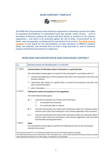
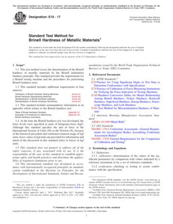
DUCTING SYSTEMSNon-Metallic Expansion JointsACorrosion Resistant Materials of ConstructionModern technology materials enable the use in aggressive chemical conditions.A- 4.1.2. Multi-Layer ConstructionAn expansion joint in which the various plies are of different materials which are not integrally bonded together.Noise and Vibration ResistanceNon-metallic expansion joints provide a high degree ofnoise isolation and vibration damping.Gas Seal MembraneInsulating LayerInsulationRetainer LayerEase of InstallationNon-metallic expansion joints are relatively lightweightand can be hoisted into place with a minimum of fieldassembly required.Flange Reinforcement (Cuff)Minimal Replacement CostThe flexible element portion of the expansion joint assembly can be replaced simply and economically.A- 4.2. Clamping ConfigurationsThere are three types of clamping configurations that mayemploy one of the above constructions;Design FreedomNon-metallic expansion joints can be tailored to suit theduct application with taper, transition or irregular shape,allowing the designer the maximum variety of options. Belt type expansion joint configuration Flanged expansion joint configuration Combination type expansion joint configurationThermal BreaksSelf-insulating properties of the fabric allow simple hot-tocold transition.A- 4.2.1. Belt-Type Expansion Joint ConfigurationAn expansion joint in which the flexible element is madelike a flat belt:A- 4. Expansion Joint Construction and ConfigurationA- 4.1 ConstructionThere are two basic forms of construction depending onthe number of layers in the expansion joint; single layerconstruction and multi-layer construction.A- 4.2.2. Flanged-Type Expansion Joint ConfigurationAn expansion joint in which the flexible element hasflanges formed at right angles.A- 4.1.1. Single Layer ConstructionAn expansion joint formed of one consolidated layer, oftenconstructed from elastomers and reinforcement materialsor fluoroplastics and reinforcement materials:BoltBack-Up BarWasherA- 4.2.3. Expansion Joint Clamping ConfigurationAn expansion joint that utilizes both belt type and flangedconfigurations.Flexible ElementWasherNutExpansion Joint Frame3 2010 Fluid Sealing Association - Non Metallic Expansion Joint Division
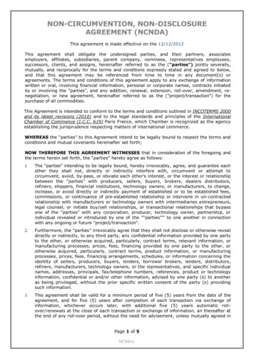
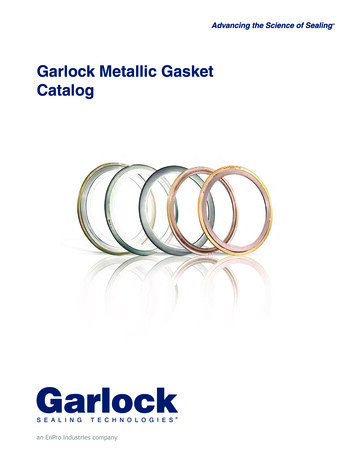
Technical Handbook4th EditionSection A - What Are Ducting Non-Metallic Expansion Joints?A- 4.3.3. Concave Type Flexible Element ConfigurationExpansion joints where the flexible element is formed intoa "U" or conical shape.A- 4.3. Flexible Element ConfigurationsIn addition to the clamping configurations shown, theflexible element may be manufactured in a variety ofconfigurations, depending on application and performance requirements:Flat Convex Concave ConvolutedIn the section below, the upper diagram represents flat belttype configuration and the lower diagram represents aflanged clamping configuration.A- 4.3.1. Flat-Type Flexible Element ConfigurationAn expansion joint where the flexible element is a flat beltwith two alternate clamping configurations.A- 4.3.4. Convoluted Type Flexible Element ConfigurationExpansion joints where large movements are accommodated through the use of multiple convolutions.A- 4.3.2. Convex-Type Flexible Element ConfigurationAn expansion joint where the arch is pre-formed to provideadditional movement capability and prevent folding of theflexible element.4
DUCTING SYSTEMSNon-Metallic Expansion JointsSection B - Expansion Joint System Design CriteriaIntroductionIn order to design the expansion joint with optimum life andoperating reliability, there are certain criteria which must beconsidered. (See Appendix-5 on page 38)BIn connection with the operation of a plant, it may benecessary to perform washing to clean fly ash build-up inthe ducting, washing of the heat exchangers or washingthe gas turbine propellers.B-1. Customer DataCustomer name and qualifier (OEM, End-user)AddressCity, State, Zip CodeName of person submitting data, Phone, FaxProject name & countryNew or replacementB- 2. ServiceInformation concerning service, type of plant and locationin the plant is probably the most important information toobtain. In most cases this information will give the supplierdetails of the demands put on the expansion joints that thesupplier will not get from all the other data on the specification sheet. The supplier's experience with thedifferent plant types and technologies is importantknowledge to utilize.In all cases it will be necessary to prevent liquids fromsoaking the expansion joints. The only exception is singlelayer expansion joints (i.e. of elastomeric or fluoroplasticmaterials installed in flue gas cleaning plants).B- 3.1B- 3.2B- 3.3B- 3.4B- 3.5B- 3.6Type of fuel (B-2.2) is important for determining the aggressiveness of the flue gas. In particular, finding the contentsof sulphur (SO2, SO3) as it may have a negative influenceon the expansion joints material, if not considered in the initial design.B- 2.1B- 2.2B- 2.3B- 2.4B- 2.5Type of plant & in plant location.(GT, Boiler, Precipitator, Scrubber, etc.)Type of fuelPeak load or base loadNumber of start/stop cycles per yearInstallation inside or outsideMedium (air, flue gas, etc.)Chemical composition (SO2, SO3, HF etc.)Medium condition (dry/wet)Dust contents and load (type, lbs/ft3 (mg/m3))Flow velocity/volume (ft/s (m/s))Washing of duct/gas turbine (yes/no)B- 4. Pressure - Pulsation & FlutterThe system operating pressure is a crucial factor affectingthe design of expansion joints. The very flexible nature ofthe materials brings a number of design issues which mustbe addressed. Although maximum operating pressures induct systems are low by comparison with pipeline systems,wide variations of pressure, such as a change from positiveto negative, or short term peak pressures can occur. Suchvariations should be reflected in the design pressure specified by the customer. Particular care in the choice andconstruction of materials must allow for:B- 3. MediumKnowing the medium is essential for deciding on materialsand design of baffle (flow liner) construction, drain, etc.Medium (B-3.1) requires a detailed description (e.g. airshould be described as combustion air, not just air). Containment of the stated design pressure under allconditions of movement and temperature, withoutover-stressing the expansion joint assembly. Changes from positive to negative pressure which couldentrap materials under compression
A-4.2.1. Belt-Type Expansion Joint Configuration . An expansion joint in which the flexible element is made like a flat belt: A-4.2.2. Flanged-Type Expansion Joint Configuration. An expansion joint in which the flexible element has flanges formed at right angles. A-4.2.3. Expansion Joint Clamping Configuration. An expansion joint that utilizes both belt type and flanged configurations.