Transcription
Heavy-Duty Conductor RailCopperHead
2
Table of ContentsCopperHead Conductor Systems4Heavy-Duty Conductor Rails.4Some Advantages of CopperHead Rail Systems.4Product Pre-Selection.4Technical Data.5Voltage Drop Calculation.6Possible Power Feed Locations.7Example Voltage Drop Calculation.7System Components9Rails.10F35 Rails F45 Rails Anchor Clamps.10Rail Joints Rail Hangers.11Power Feed Clamps Expansion Elements.12Expansion Calculation.13Insulation Joints.14Current Collectors.15Replacement Parts and Tools16Carbon Shoe Collector Spare Parts.16General Spare Parts Mounting Material Tools Cable Lugs.16System Layout17Layout Schematic and Component Overview.18Standard Installation Layout.19Current Collector Arrangement.19Installation Hints/Example.20Frequently Asked Questions21Questionnaire223
CopperHead Conductor SystemsHeavy-Duty Conductor RailsAggressive environmental conditions and rough production processes require a durable and robust conductor rail system.The Conductix-Wampfler CopperHead Conductor System is a tried and tested conductor bar system designed for heavy-dutyapplications in rough environments, such as steel mills or ship yards. Non-insulated conductor rail systems are preferred forapplications with higher ambient temperatures or temporary radiation heat, where insulated safety conductor rails are not alwaysapplicable.The CopperHead Conductor System has several new design improvements compared to traditional CopperHead rail systems,and is in line with international standards for conductor rails. The standard rail length of 6 m reduces logistic costs and optimizeshandling and installation. The improved joint technology and a production on an industrial level, supported by the ConductixWampfler quality insurance system, offer another customer benefit. Conductix-Wampfler as market leader in conductor rails andfull line provider for energy and data supply systems is a proven partner for projects all over the world.The CopperHead Conductor System is based on former non-insulated rails from Conductix-Wampfler (Delachaux, Bischoff& Hensel). Both “T” section with a span of 35/45 mm and the extruded CopperHead are drawn through a special die, whichcompresses the copper flanges around the dovetail head of the rail, connecting the two components to a 100% rigid unit.The CopperHead Conductor Rails represent a neat and compact arrangement and have proven an outstanding success for safepower feeding of various crane and transport applications. The CopperHead Conductor Rails are available in different sizes tomeet individual current requirements up to 1500 Amps.Some Advantages of CopperHead Rail SystemsWith CopperHead-Systems you eliminate all drawbacks inherent in the conventional design of trolley wires, steel anglesand steel rails. CopperHead Rails ensure an efficient and continuous contact. Usable under higher ambient temperature conditions. Limited sparking effect by high contact performance. Easy maintenance by proven system design. Reduced down times trough heavy duty. Long collector life times. Negligible wear – nearly unlimited life of conductors. Lower resistance between CopperHead and carbon bronze pick-up shoe.Main applications are: steel mills, coking plants, gas works, cement industries, ship yards and dockside enterprises.Steel CopperHead Rails are preferably used for applications in corrosive atmospheres and in locations with high humidity. The rails are supplied in 6 m ( 5 mm)standard lengths, drilled at either end for joint plates or expansion connectors. Shorter lengths are available to coincide with your run way lengths requirements.We produced a complete range of accessories, insulators and current collectors. Variation in temperature and resulting expansion and contraction is compensated bystandard expansion joints. Adequate ampere capacity must be provided to carry the anticipated electrical loads: The total ampere load is determined from the nominalrated full load current reduced by the duty cycle and by a diversity factor for non-simultaneous operation.Product Pre-SelectionBesides electrical parameters, environmental conditions and operating modes are important parameters for the product selection. The following overview will assist in thepre-selection. Further detailed information is listed under technical data.TypeIndustrial application – indoor or Highly corrosiveenvironmentExtremely corrosiveenvironment –galvanic applicationsHigherproduct safetySteel-Copper Rail 1) 2) 4)Aluminum-Steel Rail(see alternative from Conductix-Wampfler) –– 4)Copper Rail 3) *(see alternative from Conductix-Wampfler) Surface protection needed (galvanized surface) 2) Protective coating 3) Insulated copper railsFor non-insulated electrification systems, additional safety arrangements (installation height, distance, fences, etc.) according to local standards must be regarded* For full copper rail version please contact Conductix-Wampfler Sales Support1)4)4
CopperHead Conductor SystemsTechnical Data35 mmRail Type45 mmF35/50-6F35/100-6F45/50-6F45/100-6 F45/150-6 F45/200-6 F45/300-6 F45/400-6Current load at 100% duty cycle and 35 C[A]410529495620728Current load at 80% duty cycle and 35 C[A]460595560695Current load at 60% duty cycle and 35 C[A]530685645800Conductor cross section (Copper)[mm²]5010050100150Conductor cross section (Steel)[mm²]Feed Span 400352452248.5[mm]Equivalent copper cross section8264253545[mm²]89139102152202252Rail height “H”[mm]32.935.942.445.74850.85659.2Head width “a”[mm]13.51514.1151717.217.519.8Rail weight[kg/m]2.392.843.754.24.645.085.986.89Rail length[mm]6000 5DC resistance at 20 C[Ω/km]0.2040.130Impedance at 50 Hz[Ω/km]0.2930.238Nominal 0.2030.1940.1820.174Depending on insulator type, rail spacing and local regulationsRated rail spacing[mm]150Nominal suspension spacing[mm]2500System lengthUnlimited (see expansion system)Expansion systemSegmented expansion unit (see expansion section)EnvironmentIndoor and protected outdoor applicationsProtection classIP 00Temperature range-40 200 C / -40 266 FStorage temperature-30 C 40 C / -22 F 104 F (dry to prevent oxidation, no condensation)bStandard range dimensions.HFor rails with higher amperage rates, please contact Conductix-Wampfler Sales Support.aCrane Electrification according to IEC 60204-32 Standard (2009 extract)230 V400V / 230 VWARNING!These European regulations are valid for electrical installations and electrical equipment in Europe and similar to several national standards in America, Australia and Asia. Electrical installations, such as conductor rail applications must be designed to avoid direct contact with live parts. The preferred solution isan insulated and monitored system. If this is not possible, e.g. high ambient temperature where insulation material not usable, the system must be installedthat in operation and other situation can be used without a certain risk for any person. How to realize the needed safety please refer the valid regulationson-site and contact the local authority.Dangerto life from The operation of non insulated conductor rails and other electrical equipment above 48 V AC / 60 V DC without additional protection regarding local safetyhigh voltage! standards is not allowed. Electrical energy carries a high danger to life.5
CopperHead Conductor SystemsVoltage Drop CalculationThe maximum length between feeding point and freest consumer start up position are limited by the voltage drop and is depending of the installed drive system and start upconsumption.The position of the power feed can be designed at the first step by the onside situation but must be checked by the voltage drop in the start up phase of the consumer. Thevoltage drop must be less than 5% or related to the customer specification. If the voltage drop exceed, the limit the rail cross section must be increased or the power feed inposition and/or amount must be adapted.After selecting the rail type based on the calculated total current depending on duty cycle and ambient temperature, the voltage drop must be checked. The calculated voltage drop must be under the value specified by the customer. Typical values here are 2-5% or 10% in exceptional cases. If the voltage drop is too high, the voltage might betoo low to all the drives to start.The following formulas are used for the calculation:For direct currentU 35 C voltage drop at 35 CU 35 C 2 · I · IA · RIA total currentFor alternating currentU 35 C 2 · I · IA · Z · cos ϕ[A]R resistance of the conductor rail[Ω/m]Z impedance of the conductor rail[Ω/m][V]I feed lengthFor three-phase powerU 35 C 3 · I · IA · Z · cos ϕ[V][V][m][V]cos ϕ phase distance angleNote: IA here is the portion of the load current “drawn” during start-up. (IA IB IA')This consists of the basic load IB, like lighting and air conditioners, and the start-up currents of the drives IA'.For start-up current, the following applies:Three-phase asynchronous drive in direct start:Slip ring rotor motor:Frequency converter:6IA' IN x 5 to 6 (up to max. 21 kW permitted)IA' IN x 3 to 5IA' IN x 1.2 to 1.4IA total current IB IA'IA' total current when startingIN Nominal Engine Current
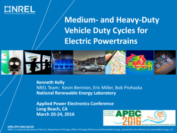
CopperHead Conductor SystemsPossible Power Feed LocationsThe power feed arrangement must be appropriate for the specific case, since the voltage drop is calculated with the feed length “l ” that falls between the power feed andthe end of the conductor rail. The following power feed options are normally used:End power feedI LWith an end power feedI L/2 With a middle power feedI L/4 For two power feeds at both endsI L/6 For two power feeds each L/6from the endsI L/10 For a power feed in the middleand L/10 from each endI L/14 For four power feed pointsI LMiddle power feedI L/2LPower feed on both sidesL length of the conductor rail [m]I L/4L/6 power feedI L/6LI L/6L/10 power feedI L/10I L/10I L/2LL/14 power feedI L/14I L 5/14I L 9/14I L/14LExample Voltage Drop CalculationThe average crane motor duty cycle is usually between 40% and 60%, depending on the type of application. A diversity factor of 0.4 to 0.7 can be mostly used when there ismore than one crane on the same runway. Example:Start up current- 1 crane, I 500 Amps. (50 Amp auxiliary consumers450 A drive and lift motor consumption)- Power supply 690 V AC, 3-phase- Length of runway: 100 m (330 ft.)- Typical crane duty cycle: 60% (ED)- Assumed diversity factor: 0.7 per crane (hoist, trolley gantry)- Converter drive System Start up factor: 1,3Ampere load crane 50 A (450 A x 0.7) 50 A 315 AStart up Current System 50 A 315 A x 1.3 IG 460 A- Total ampere load when starting: 460 A- Selected conductors: F35/100 OR F45/50- Voltage drop U 5% x 690 34.5 V- Feed length I U35 C /( 3 · IG· Z ) 194 m- Selected power feed location: End power feed.7
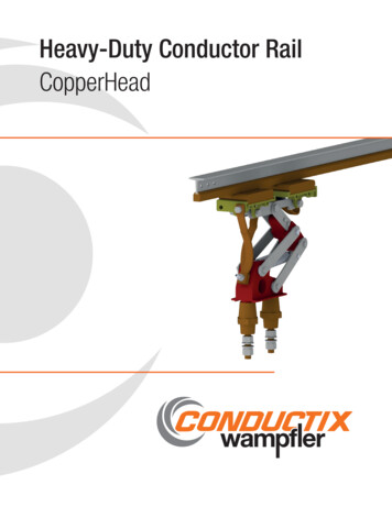
CopperHead Conductor SystemsComponentsThe System ComponentsCopperHead conductor rails are based on the combination of universally applicable standard components. Design, length and material are optimized to fulfill the requirements in logistic, installation, operation and maintenance of steel mills and similar rough crane indoor and protected outdoor applications.The components: CopperHead rails with rigid steel base for rough environments where aluminum or fully insulated rails reach their limits Easy to use rail joints Hanger clamps with insulators to hold the rail in position and insulate it from the base steel structure Anchor clamps to mount the rail against movement to the structure Massive power feed elements with low resistance and solid build for the cable connection on-site Expansion joints for length compensation Air insulation elements for rail segmentation, e.g. maintenance segment1 Insulated rail hanger2 Expansion joint3 Rail joint4 Collector assembly1525 CopperHead rail34The Conductix-Wampfler CopperHead rail is steel-based and in accordance with the international standard design of non-insulated rail systems for crane applications.The efficiently sized 6 m rail reduces logistic costs and allows for easy installation and distribution of the system. This length is conforming to the international standardlength for steel profiles and is compatible with handling/transport and storage equipment. Shorter rail segments can be easily cut on-site with standard equipment.Individual rail lengths are available on request, subject to minimum order lot size.System Arrangement and Interface to the Building/Crane Structure on-siteThe interface to the structure on-site is a typical system integration engineering task and can be offered as engineering service form our local sales and service subsidiary orpartners. Please contact your local Conductix-Wampfler sales and service (see www.conductix.com for contact information).Hanger distance, type of insulator, installation height, access distance and other design aspects are depending on the supply voltage level and the local electrical and safetyregulations. In addition to national regulations often end customer safety specifications have to be taken observed.Non insulated rails carry a higher risk for material damage and danger to life and require additional on-site safety precautions.For details refer to local standards or to the responsible authority on-site.9
CopperHead Conductor SystemsComponentsRails20a3030Type F35: 6 x Ø10Type F45: 6 x Ø12H Standard length: 6 m /- 5 mm Installation position: horizontalor lateral installation setup Base: pure/galvanized Head: massive electrical copper6000 5bF35 RailsOrder No.Rail TypeMax. continuous100% DC/60% DC [A]Copper crosssection[mm2]Steel crosssection[mm2]H[mm]a[mm]b[mm]Cu weightkg/6 mRail weightkg/6 8529/685100248.535.915355.3417.04Max. continuous100% DC/60% DC [A]Copper crosssection[mm2]Steel crosssection[mm2]H[mm]a[mm]b[mm]Cu weightkg/6 mRail weightkg/6 m22.5F45 RailsOrder No.Rail 01R967801R9681156/150040042559.219.84521.3441.16 Anchor to hold the rail in positionMaterial: steelInstallation torque: 25 NmAmount for rail and fixing point 2 piecesContent of delivery:hanger with fasteners28M8Anchor R121Rail anchor for rail hanger F35 type0.06545801R122Rail anchor for rail hanger F45 type0.072
CopperHead Conductor SystemsComponentsRail Joints Rail connector device incl. mounting materialMaterial: brassInstallation torque: 25 NmContent of delivery:joints with fastenersType 354 x Ø8.5120Type 456 x ail joint F35 rail ASSY0.11645801R211Rail joint F 45 rail ASSY0.19–310932Joint compound (for approx. 80 joints)0.03Rail 1R283306070.54.1108Mthr 16eadedbolt15Rail hangerMaterial: steelInstallation torque: 25 NmMax. hanger distance: 2500 mmMax. insulator voltage: 1 kV(higher voltage on request) Temperature range:-40 C (-40 F). 130 C (266 F)(higher temperature range on request) Insulator for indoor andprotected outdoor installation Included in delivery28 DescriptionRail hanger for F35 railsRail hanger for F 45 11
CopperHead Conductor SystemsComponentsØFor power feed cable connectionMaterial: copper, brassInstallation torque: 25 NmMax. cable cross section: 630 mm²Max. bolt size: M8 x 40 mmContent of delivery:power feed plate,joints and fasteners5M10 12.522 .*Power Feed Clamps* Ø 12.5 ex factory, bigger diameters can be adapted on-site (max. 22 mm)OrderNo.DescriptionMax. Current[A]Weight[kg]35801R151Power feed clamp for F35 rail type20220.4945801R152Power feed clamp for F45 rail type20220.51TypeExpansion Elements15.250.8 Length compensation element Material: copper brass Installation torque: 25 Nm1000451065OrderNo.35-50801R2607812TypeØThe expansion element is installed instead of a rail joint.The expansion elements includes: expansion bar, joint,short joint, copper strip, screws, washers, nuts.DescriptionExpansionway [mm]Expansion ASSY 50 mm² for 35-50 (with galvanization)MaterialWeight[kg]Copper, Brass3.135-100801R360Expansion ASSY 100 mm² for 35-100 (with galvanization)Copper, Brass3.745-50801R460Expansion ASSY 50 mm² for 45-50 (with galvanization)Copper, Brass4.14.545-100801R560Expansion ASSY 100 mm² for 45-100 (with galvanization)Copper, Brass45-150801R660Expansion ASSY 150 mm² for 45-150 (with galvanization)Copper, Brass5.145-200801R760Expansion ASSY 200 mm² for 45-200 (with galvanization)Copper, Brass5.545-300801R860Expansion ASSY 300 mm² for 45-300 (with galvanization)Copper, Brass6.545-400801R960Expansion ASSY 400 mm² for 45-400 (with galvanization)Copper, Brass7.535-50801R270Expansion ASSY 50 mm² for 35-50 (without galvanization)Copper, Brass3.13.75835-100801R370Expansion ASSY 100 mm² for 35-100 (without galvanization)Copper, Brass45-50801R470Expansion ASSY 50 mm² for 45-50 (without galvanization)Copper, Brass4.145-100801R570Expansion ASSY 100 mm² for 45-100 (without galvanization)Copper, Brass4.545-150801R670Expansion ASSY 150 mm² for 45-150 (without galvanization)Copper, Brass5.145-200801R770Expansion ASSY 200 mm² for 45-200 (without galvanization)Copper, Brass5.545-300801R870Expansion ASSY 300 mm² for 45-300 (without galvanization)Copper, Brass6.545-400801R970Expansion ASSY 400 mm² for 45-400 (without galvanization)Copper, Brass7.5
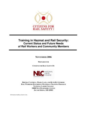
CopperHead Conductor SystemsComponentsAmbient temperature during installation [ C]Expansion Calculationtmax 80 70 60 50 40 30 20 100-10-20-30tminLegend:tmin lowest temperature that occurs in the applicationtmax highest possible working temperature in the applicationExample:Temperature range: from 0 C to 25 CAmbient temperature during installation: 25 CSteel rail air gap: 19 mm0102030405060708090Air gap [mm] for 100 m systemThe chart shows orientation lines for the conductor rail, considering 100 m expansion joint intervals. For gap setting move the orientation line in parallel up to the pointpresenting the anticipated max ambient temperature. Then connect point of actual ambient temperature during installation to the right until intersecting with the orientationline. Follow the vertical axis downward to read the air gap dimension in mm.For installation above 100 m the amount and position of the expansions will be engineered based on the application input individual.The rail system is mainly installed on a steel or concrete structure. The thermal expansion of the rail and this structure are very close and theoretical no expansion areneeded by changes of the ambient temperature. In application with local high temperature effects and temperature changing or longer installation above 100 m systemlength a expansion unit are recommended. At expansion on building and structure side also a expansion on the rail system are needed corresponding with the buildingexpansion section. For installation above 100 m the amount and position of the expansions will be engineered based on the application input individual.Please contact our Technical / Sales Support if you need any support with the calculation.tges tU tswt U Temperature range of the ambient temperaturetsw Temperature increase due to electric current (electrical thermal load)Recommended values for tsw:10 C up to 40% duty cycle20 C up to 65% duty cycle30 C up to 100% duty cycleFor longer systems than those in the table above, use:L - 100 number of Expansion Units (L: system length, a: expansion way)aConnect the rails by rigid or expansion joints using the holes provided at the ends of the 6 m sections. For systems up to 100 m no expansion joints required. With longerruns use an expansion joint after every 6 standard lengths of 6 m intervals. For special heat environment and strong temperature fluctuations reduce these intervals to 28 m.For gap setting see adjacent diagram and example. Provide an extra insulator/Rail support close to each expansion joint – approx. 250 mm.13
CopperHead Conductor SystemsComponentsInsulation JointsRail insulation segment to separate the rail track in segmentsMaterial: PTFEMax. Voltage: 1000 VInstallation torque: 25 NmAir distance: 60/180 mmContent of delivery:insulation elements,fasteners6030 1803180300Type14DescriptionOrder No. (forGap length 60 mm)Weight[kg]Order No. (forGap length 180 mm)Weight[kg]35/50Insulation Joint for CopperHead rail 35-50801R2370.329801R2380.42235/100Insulation Joint for CopperHead rail 35-100801R3370.335801R3380.42845/50Insulation Joint for CopperHead rail 45-50801R4370.451801R4380.63445/100Insulation Joint for CopperHead rail 45-100801R5370.456801R5380.64845/150Insulation Joint for CopperHead rail 45-150801R6370.462801R6380.66745/200Insulation Joint for CopperHead rail 45-200801R7370.469801R7380.68845/300Insulation Joint for CopperHead rail 45-300801R8370.481801R8380.72445/400Insulation Joint for CopperHead rail 45-400801R9370.496801R9380.769
CopperHead Conductor SystemsComponentsCurrent Collectors12510512580 152110M10M16max.3017.550M16 15280M10Lowest operating position: 280Stroke: 150Stroke: 1501055086230Lowest operating position: 280 Current collector: max. 450 A / 900 A Max. voltage: 1 kV(higher voltage on request) Temperature range: -40 C (-40 F). 130 C (266 F)(higher temperature range on request) Material: steel, copper, plastic Collector brush: carbon-bronze Content of delivery:collectors, frame, copper belt,insulator, fasteners17.5110insulated socketwithout ght [mm]Nom.Current [A]Weight[kg]Single394176Single shoe collector with insulated socket 69027545020.6Single801R177Single shoe collector with insulated socket insulator 300035545022.2Double394196Double shoe collector with insulated socket 69027590026.7Double801R197Double shoe collector with insulated socket insulator 300 035590028.2Type15
CopperHead Conductor SystemsReplacement Parts and ToolsCarbon Shoe / Collector Spare PartsSystem performance requires the optimized material and original spare parts to prevent breakdowns and ensure durability. Copies and non-conform spare parts can increaserail wear.17TypeOrder No.DescriptionWeight [kg]393401Spare brush 450 A2.152395041Mounting set for spare brush0.4763935405Collector spring ng strand0.616944008Connecting strand0.717393702Shoe holder1.8General Spare Parts / Mounting Material ToolsItemOrder No.DescriptionUnitWeight [kg]1W80022M8x40 GB/T5782 M8x16 HEX HEAD SETSCREW Z/PPcs.0.129209M8 GB/T6170 M8 FULL NUT Z/PPcs.0.13801R420InsulatorPcs.0.74310932Joint CompoundPcs.0.03Copper terminals connect the power cable and electric equipment, which is made of T2 copper bar.Cable m2]øDdLL1BDTS-505010.5149.5853823Dimensions 45352208580DT-800DTS-80080021503826085100
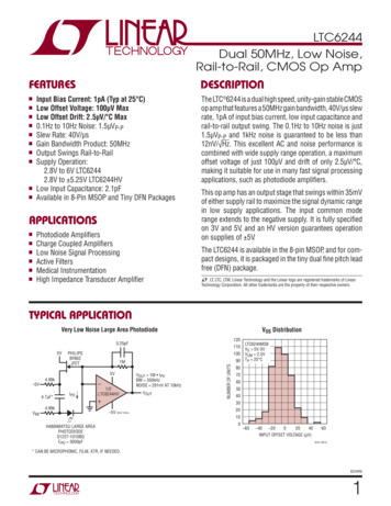
154 - 185Installation height H110150 min.450Current CollectorAnchor Clamp100M16Insulator2500Rail JointM162500-5355 25-10275 25-15H(mm)-10801R177-53941760Collector assy type 5C 6 x 2500 mm275 253941960 5355 25 5260 25801R178 15 10801R197 10260 25801R1980250End Power FeedRail Hanger OffsetWe recommend installing the rails in a Zigzag manner to prevent irregular brush wear.Rail offset is 15 mm.Expansion Joint250060131 - 1516000-5CopperHead Conductor SystemsSystem LayoutSystem Layout17
CopperHead Conductor SystemsSystem LayoutLayout Schematic and Component OverviewExample: 100 m steel rail system a 2.5 m2.5 m6m6m33 m33 m100 mPower feedHanger clamp & hanger clamp bracket JointAnchor clampExpansion sectionInstallation noteRegarding the first and the last conductor rail a support distance of 1750 and 250 mm from the beginning resp. the end of the rail is to be provided. Apart from that thesupport spacing is 2.5 m. The earth collector should always be installed on the outside. The centre distance between two conductors can be taken from the table below.Distancebetween centersof two conductor railsMinimum distance a [mm]L1 L2 L3 PEStandard voltagearrangementHigh voltagearrangement150 250*a* consider local regulationsaaExample material overviewHere is a typical crane conductor rail system that is 57 m in total length, with 4 poles, 800 A, with all accessories, Current collectors and support arms. The required Bill ofMaterials is listed below. The order quantity should be increased by an assembly reserve for the parts marked with an (X).18Part DescriptionOrder No.Quantity NeededConductor rail 6 m long801R767 6mX3636Conductor rail 2 m long801R767 2mX44Hanger clamp801R28280 (X)Anchor clamp801R1228 (X)Power feed801R1524 (X)45 Joint ASSY801R21136 (X)
CopperHead Conductor SystemsSystem LayoutStandard Installation LayoutHorizontal installation of conductor rails/Vertical insertion of Current CollectorsVertical installation of conductor rails/Horizontal insertion of Current CollectorsCurrent Collector Arrangement/Hanger Distance150max. 2500For installations w
The CopperHead Conductor System has several new design improvements compared to traditional CopperHead rail systems, and is in line with international standards for conductor rails. The standard rail length of 6 m reduces logistic costs and optimizes handling and installation. The improved joint technology and a production on an industrial .