Transcription
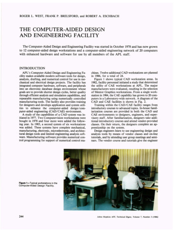
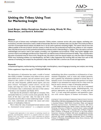
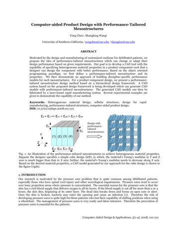
Computer-aided Product Design with Performance-TailoredMesostructuresYong Chen1, Shanglong Wang2University of Southern California, 1yongchen@usc.edu, 2shanglow@usc.eduABSTRACTMotivated by the design and manufacturing of customized cushions for debilitated patients, wepropose the idea of performance-tailored mesostructures which can change or adapt theirdesign performance based on given requirements. Our goal is to develop a CAD tool with thecapability of specifying heterogeneous material properties in a product component such that adesigner can design the component with better performance. Based on the object orientedprogramming paradigm, we first define a performance-tailored mesostructure and itsproperties. We then demonstrate an approach of building discipline-specific performancemodels for such mesostructures. For a product component design, we present a performancetailored mesostructure design method based on a hierarchical design framework. A CADsystem based on the proposed design framework is being developed which can generate CADmodels with performance-tailored mesostructures. The generated CAD models can then befabricated by a layer-based rapid manufacturing system. Several experimental examples aregiven to demonstrate the capability of our method.Keywords: Heterogeneous material design, cellular structures, designmanufacturing, performance-tailored structures, computer-aided product design.DOI: 10.3722/cadaps.2008.xxx-yyyforrapidDesign withperformancetailoredmesostructuresFig. 1: An illustration of the performance-tailored mesostructures to achieve heterogeneous material properties.Suppose the designer specifies a simple cube design (left), in which, the material’s Young’s modulus in Y and Zaxes is much bigger than that in X axis; further, the material’s Young’s modulus needs to decrease along X axis.Based on the desired material properties, a CAD model generated by our approach for the cube design is shown inthe figure (right).1. INTRODUCTIONOur research is motivated by the pressure sore problem that is quite common among debilitated patients,especially those who have spinal cord injury and other neurological impairments. Pressure sores tend to occurover bony projection areas where pressure is concentrated. The essential reason for the pressure sore is that theskin has a rich blood supply that delivers oxygen to all its layers. If the blood supply is cut off for more than 2 or 3hours, the skin dies, beginning at its outer layer. The dead skin breaks down and forms an open sore or ulcer.Once the skin is broken, bacteria may enter the opening and cause an infection [1]. Therefore the risk ofdeveloping pressure sores is quite high for those patients who lost their capability of shifting positions when usinga wheelchair. The management of pressure sores is very costly and labor-intensive. Therefore the prevention ofpressure sores is essential for the patients.Computer-Aided Design & Applications, 5(1-4), 2008, xxx-yyy
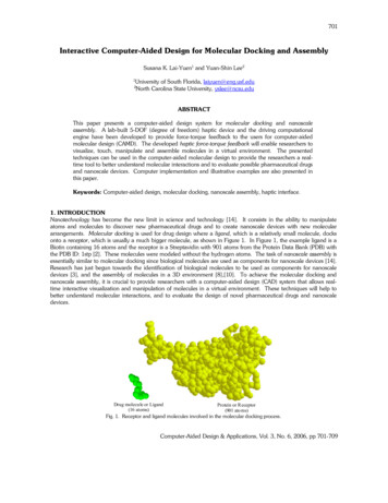
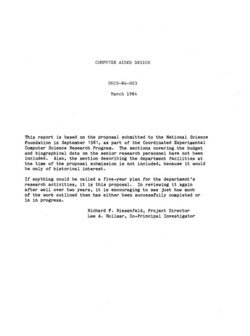
2(2)(1)(2)(1)SoftFirm(1)FirmFig. 2: Pressure redistribution in cushion design (provided by Richard Pasillas at Cushmaker.com).In many cases, an optimal cushion design for the wheelchair is the most effective means of preventing pressuresores. For a long period of time, people have been using soft materials in the cushion design to reduce pressures.For example, comparing the usage of a rigid flat surface (e.g. E 10,000 kPa) and a firm foam cushion (e.g. E 100kPa) as the contact surface, the foam cushion can help to significantly reduce the maximum internal tissuestresses. Many different types of soft materials have been used in the cushion design. However, the cushiondesign based on soft materials such as air-cell or gel-pad can only reduce and equalize all contact pressures. Thepressure over bony projection areas may still block the blood supply. Therefore, the pressure sores may stillhappen to those debilitated patients.A more effective way to reduce the pressure sore problem is based on “pressure redistribution” [2]. That is, acushion designer can repartition the contact surface and selectively increase or decrease the contact pressure atspecific sites or regions. In a sitting position as shown in Figure 2 (left), the posterior thigh region, marked as (1),is less prone to pressure sores than the trochanter area, marked as (2). This is become the distribution of bloodvessels and tissue structures in these regions are different. Therefore, an optimized scheme in the cushion designis to develop a cushion such that it can shift the pressure from the areas that can't handle the pressure to the areasthat can. The risk of developing pressure sores is greatly reduced by such a cushion that can minimize the intratissue stress in the critical areas that are prone to pressure sores.An ideal CAD tool, therefore, is to allow a cushion designer to repartition the shape of a seat cushion into smallregions and specify the firmness of each region based on the desired pressure distribution. An example fromRichard Pasillas at Cushmaker.com is shown in Figure 2 – (right). Currently foams with a variety of density aremanually cut into multiple layers and glue together to fit a patient’s custom contour. However, designing such anadequate cushion has been a trial-and-error process since many factors govern the cushion’s effectiveness forpressure relief. In addition, the limited selection of foams or plastics can limit the designer’s capability indesigning such a cushion. Therefore, it is quite costly for a patient to buy a truly customized cushion for his/herwheelchair.Layer-based additive manufacturing processes, such as stereolithgraphy (SLA) and selective laser sintering (SLS),have been used for prototyping for nearly twenty years (rapid prototyping). A main benefit of a rapid prototypingprocess is its ability to build arbitrary geometries without tooling. Parts with complex geometries can bemanufactured by these processes without cost penalty. In recent year, layer manufacturing processes have beenused as a direct manufacturing approach (rapid manufacturing) for aerospace and medical applications. Rapidmanufacturing is expected to have a big impact to the future product design and manufacturing [3]. We believethe design and manufacturing of customized cushions can greatly benefit from rapid manufacturing since eachcushion is unique based on a patient’s specific needs.In this paper we present a novel product design method based on an idea of performance-tailored mesostructuresfor achieving heterogeneous material properties that are common in many applications. An illustrative example isshown in Figure 1. In our method, the designer only needs to specify the performance required in each region of aproduct component. Our approach and related algorithms will select a suitable mesostructure from amesostructure library for each region; further we will tailor the geometric parameters of each mesostructure tomatch the specified performance. Finally based on the common boundaries specified in the structure library, weautomatically connect all the mesostructures together to generate a valid CAD model for rapid manufacturingsystems. As illustrated in Figure 1, the CAD model generated by our approach fully utilizes the geometriccapability of rapid manufacturing processes. The work is part of an effort in developing a CAD tool that gives thecushion designers the most flexibility in designing customized cushions to reduce the possibility of pressure sore.The central contributions of this paper are the definition of a performance-tailored mesostructure and relateddesign method for an optimal component design. The reminder of the paper is organized in the following way. InSection 2, we define the performance-tailored mesostructure and present the basic idea of using it to achieveComputer-Aided Design & Applications, 5(1-4), 2008, xxx-yyy
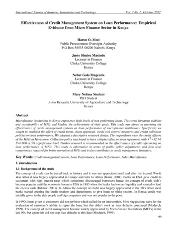
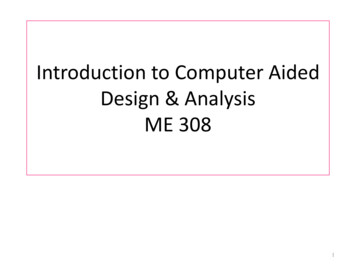
3heterogeneous material properties. Section 3 illustrates the approach of building functional performance modelsfor a performance-tailored mesostructure library. In Section 4, a hierarchical design framework is presented tointegrate the performance-tailored mesostructure with the functional models in the component level. Section 5summaries our efforts in developing a CAD tool based on the design framework. Two examples are also given toillustrate the capability of our testbed. Finally, conclusions are drawn in Section 6.2. HETEROGENEOUS MATERIAL PROPERTIES BASED ON MESOSTRUCTURESWe are interested in the design of a product component. In this paper, a mesostructure refers to the geometricarrangement of materials within a unit cell on a scale that is insignificant compared to the scale of the component.The characteristic length of a mesostructure is in the range of 0.1 to 10mm for layer-based rapid manufacturingprocesses [4]. If a component is solid, its behavior depends on the part geometry and the material property;however, if mesostructures are used in the component, its behavior will also depend on the configuration of themesostructures. For example, polyhedron, such as tetrahedron and octahedron, are popular mesostructures [5, 6].An example of applying a polyhedron in a component is shown in Figure 3 (top) [7]. In addition to the simplepolyhedron, researchers in the field of material design have presented various meso/micro-structures for differentdesign purposes. For example, Sigmund [8] presented a micro-structure to get material behavior similar to arubber band. An example of applying Sigmund’s mesostructure in a component design is shown in Figure 3(bottom) [9]. Fig. 3: Two examples of applying mesostructures in a component design [7, 9].Instead of applying a single mesostructure inside a component such as the two examples shown in Figure 3, wecan use various mesostructures at different locations to achieve heterogeneous material properties. That is, for ancomponent G, we can subdivide it into a set of cells Ci such that G Ci . For each cell Ci, we can then map ai 1mesostructure Mi into the cell and use mesostructure boundary connectors Bi to connect Mi with its neighboringnmesostructures. Therefore we can generate a new model G ' ( M i Bi ) . During the above subdivision andi 1mapping processes, we can change the material property at Ci by:(1) Using different cell subdivisions: A component G can be subdivided by using different cell sizesand orientations. For example, as shown in [7], we used one or several design requirements to define awarping function f(V) and used a space warping technique to minimize an energy functionE (V ) 21f (v j ) vi v j . Consequently the modified cell subdivision is more adaptive to the given 2 i j Nipart shape and design requirements.(2) Using different mesostructure topology: As shown in Figure 3, the topology of a microstructureplays a big role in determining its structural properties. Different geometric configurations, such as thestrut connectivity, can lead to rigid or flexible behaviors [10].(3) Using different mesostructure geometry: For the same mesostructure orientation and topology,we can also use different design parameter values to generate different geometries. For example, a strutas shown in Figure 3 can have different sizes. Correspondingly, the mesostructures will have differentmaterial behaviors.Computer-Aided Design & Applications, Vol. 4, Nos. 1-4, 2008, pp xxx-yyy
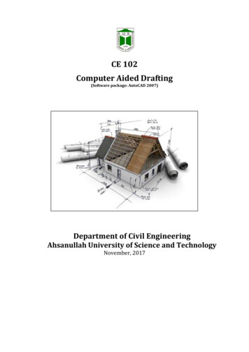
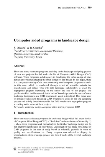
4Therefore, we can use different mesostructures to achieve truly heterogeneous material behaviors even though arapid manufacturing process such as SLA and SLS provides only a single material such as A6 steel orthermoplastics. Some related work presented the similar idea. Wang [11] presented a unit cell approach fordesigning lightweight structure and compliant mechanism; Rosen [4] presented a framework for cellular materialdesign for additive manufacturing; and Gupta et al. used staggered cell configuration to achieve graded stiffness[12]. Our work is different from the functionally gradient materials (FGM) research for modeling heterogeneousmaterials for a manufacturing process that can control the material variations in a component [13-15]. However,both types of researches are complimentary. That is, the structural variation in addition to the material variationwill enable us to achieve a wide range of material properties.Our research focuses on how to use controlled structural variation to achieve desired material properties. We firstdefine a performance-tailored mesostructure based on the object-oriented programming (OOP) methodology.The OOP is a programming paradigm that uses “objects” and their interactions to design software systems.Currently it is commonly used in the software development. The OOP paradigm enables an object (data andfunctions) to be reused. The basic pillars of the OOP that are closely related to our application includeencapsulation, data hiding, and polymorphism. Encapsulation refers to the property of being a self-containedunit. Data hiding refers to the ability of using any object without the user knowing or caring about how it worksinternally. Polymorphism refers to the ability of objects belonging to different data types while respond to samemethod calls.Similar to an object as defined in the OOP, a performancetailored mesostructure consists of four key components: (1)structural configuration (topology), (2) design parameters(geometry), (3) defined boundary, and (4) functionalperformance. They are explained in more details by using amesostructure example as shown in Figure 4, which is used togenerate the CAD model as shown in Figure 1.(1) Structural configuration: The topology of a mesostructureplays a big role in determining its structural properties. Theresearches in material design have developed a lot of structuralconfigurations for different design purposes. For example,Larsen et al. [16] developed a structure that possesses theunusual property of having a negative Poisson’s ratio. Amesostructure can also integrate very dissimilar physicalFig. 4: An example of a performance-tailoredprinciples. For example, the mesostructure as shown in Figuremesostructure that is used to generate the CAD4 mainly uses strut’s stretch and compress in Y and Z axes whilemodel as shown in Figure 1.it mainly uses strut’s bending in X axis. In addition to structuralproperties, other properties such as thermal or acoustic properties can also be used to determine the structuralconfigurations. We use a general definition scheme to define a structural configuration and represent amesostructure in a XML file [9].(2) Design parameters: A structural configuration and corresponding physical principles give us a range ofperformance that the mesostructure can achieve. For a desired performance within the range, we can changedesign parameter values to tailor its geometry for achieving it. If the parametric design approach is used to definea mesostructure, we can easily change its geometry by modifying the design parameters. For example, themesostructure as shown in Figure 4 are defined by a set of design parameters such as RY, RZ and rSpring. Bychanging their values, we can generate a mesostructure to achieve a desired property within its property range.(3) Structural boundary: Each mesostructure has a set of defined boundaries. They are the interface betweenneighboring mesostructures. As shown in Section 4, a CAD model synthesizer can automatically integrate all themesostructures in a component into a valid CAD model. The synthesizer only needs to know the mesostructures’boundaries. The inside geometry of a mesostructure can be hidden. Further, if we define a set of standardboundary, we can change the internal mesostructure geometries without affecting their connections. Thereforewe can use different elements to replace a strut. An example is shown in Figure 10.(4) Functional performance: The mesostructure’s performance model is intended to describe its functionality. Itincludes a set of performance ranges and related functions. A performance range is related to the structuralconfiguration, material property and manufacturing process that will be used to fabricate the mesostructures. Forexample, a rapid manufacturing process has its limitation on the minimum feature size. Therefore, each designparameter can only have a feasible range in order for the mesostructure to be manufacturable. Correspondingly,the mesostructure will have a limited performance range. A performance function based on the design parametersComputer-Aided Design & Applications, 5(1-4), 2008, xxx-yyy
5can be in any forms such as an analytical function, a predefined finite element analysis program, a set ofexperimental data, or as simple as a prior analysis result. It also needs to consider the dominant physicalprinciples. For example, for the spring in X axis, we need to consider both axis forces and bending moments. Wemay also have multiple performance functions. For example, for the mesostructure as shown in Figure 4, we willhave three different performance functions corresponding to the three axes respectively. Similar to using anobject in the OOP, a designer only needs to know the mesostructure’s performance in each axis. Its internalstructures and related physical principles for achieving the performance can be hidden from the designer. Asdiscussed in the next section, we can build a mesostructure library and find a matching mesostructure based onthe desired performance.3. BUILDING MESOSTRUCTURE’S FUNCTIONAL PERFORMANCE MODELIn this section, we illustrate the approach of building the functional performance model of a performance-tailoredmesostructure. It further demonstrates the key ideas that are presented in Section 2. We use a diaphragm flexuredesign [17] as the structural configuration of a mesostructure. This also demonstrates that a mesostructure canhave a much more complex configuration than a popularly used polyhedron. The 3D view and top view of thedefined mesostructure are shown in Figure 5. The central section of the mesostructure is a solid plate. Itsoutskirts are four uniformly distributed sub-structures which enable the solid plate to have a relatively largedeformation when an external force is exerted on the plate. We build a parametric design model of the structure.The important design parameters are marked as A G as shown in Figure 5-right. For the same external force, wecan change these parameters to generate mesostructures that can achieve different central . 5: A mesostructure and its design parameters based on adiaphragm flexure design [17].Fig. 6: Pareto chart of the parameter effectrelated to the central displacement.Suppose the central displacement is the design performance that a designer is interested in (e.g. for thecustomized cushion design). We use a finite element analysis software system (COMSOL) to quantify the relationbetween the design parameters and the central displacement. Suppose we will use a SLS machine with DuraFormPA plastic, both from 3D Systems Inc. (www.3dsystems.com), to fabricate the CAD model. The materialproperties of DuraForm PA are used in the FEA simulation. Among the parameter A G, we first design a set ofexperiments to find out the most significant design variables related to the desired performance. A fractionalfactorial design based on 7 factors is generated. Accordingly, 16 FEA experiments are performed for the centraldisplacement. An experimental analysis software system (MINITAB) is used to analyze the experimental results.The Pareto chart of the parameter effect is shown in Figure 6. Based on the experimental analysis, the mostsignificant factors that contribute to the central displacement are E, D, and F.Accordingly we fix the design parameters (A, B, C, and G), and design another set of experiments with only thesignificant design parameters (E, D, and F). A total of 120 FEA analyses are performed. Based on the analysisresults, we use MINITAB to generate a quadratic regression model between the central displacement and thedesign parameters. The estimated response surface model is shown as follows.Central Disp(D, E, F) 0.1563 - 1.4691E 0.0450F -0.2301D 5.2845E*E 0.1223D*D 1.0261E*D.We use the original FEA analysis results to verify the generated regression model. We also perform additionalFEA analysis to verify the generated regression model. The differences between FEA simulations and the datacalculated by the quadratic regression model are within 5%. Therefore, the regression model is validated. For astructure with specified design parameters A G, we can then use the regression model to directly estimate thecentral displacement. This will significantly improve the performance of the optimization process in finding ageometric configuration for a desired central displacement.Computer-Aided Design & Applications, Vol. 4, Nos. 1-4, 2008, pp xxx-yyy
6MesostructureBoundaryFig. 7: A clamped circular plate under distributedbody force [18].Fig. 8: (left) A photo of the built mesostructure with twosets of parameter values; (right) a mesostructure withspring design that can achieve a bigger centraldisplacement than the mesostructure as shown in Figure 5.To simplify the material selection, we can also calculate the mesostructure’s equivalent material property.Suppose a designer would like to match the Young’s Module E in a small region. For a circular plate with fixedsupports around its outer boundary (refer to Figure 7), the central displacement of a clamped circular plate under24distributed body force can be expressed as: Central Disp 3(1 v ) qa [18], where q is the distributed loading34 Etpressure, t is the thickness, and ν is the Poisson ratio. Therefore, the Young’s Module of the plate is:3(1 v 2 )qa 4. Applying it in our mesostructure, we can calculate the equivalent E value from theE 4 Central Disp t 3central displacement of a geometric configuration (A G) by Eequivalent 3(1 v 2 )qa 4.4Central Disp ( D, E , F ) t 3In our customized cushion design example, we can use Eequivalent value to evaluate the material property at a smallregion. For a target Eequivalent value, we can identify design parameters based on the equation and accordinglygenerate a mesostructure. For example, a photo of the built mesostructures with two sets of parameter values isshown in Figure 8 (left). Notice each design parameter can only vary within a limited range due to the topologicaland manufacturing constraints of the mesostructure. Therefore the mesostructure can only achieve a limitedrange of central displacement. Correspondingly the mesostructure has a limited range of Eequivalent values.If a target Eequivalent value is out of the range [Eequivalent min, Eequivalent max] of a mesostructure, we need to useanother type of mesostructure in the region. For example, in order to achieve a much smaller Eequivalent value (i.e.to generate a much bigger central displacement), we can use a mesostructure as shown in Figure 8 (right) whichutilizes simple spring design. Similar to the diaphragm mesostructure, we can identify its design parameters,structural boundary and build a Eequivalent model. A photo of the built spring mesostructure is shown in Figure 8(right). A simple test verifies that the spring mesostructure can indeed achieve a much bigger centraldisplacement for the same force. Consequently it has a different range of Eequivalent values. Another type of ureFig. 9: An illustrative example of applyingAshby chart for the mesostructure selection.B3B’4B4S’2B’3Fig. 10: An illustrative example of applying the idea ofperformance-tailored mesostructure to its element level.Computer-Aided Design & Applications, 5(1-4), 2008, xxx-yyy
7based on staggered cells was presented in [12], which has a different Eequivalent model. Therefore, we can build amesostructure library to have a wide range of Eequivalent values. A designer can choose from them for better designperformance. The library is reusable and scalable. As shown in Section 4, a mesostructure selector can also bedeveloped to aid the designer to select an appropriate mesostructure from the library. In mechanical design,Ashby [19] developed a property cross-plot approach to quantify property-performance relations for the purposeof material selection. We can generate a similar chart based on the Eequivalent range for a mesostructure and a rapidmanufacturing process. The chart can then be used by the designer in mesostructure selection (refer to Figure 9).Notice the range of performance that can be achieved by the mesostructures can be significantly expanded thanthat of the solid material.We can further extend the idea of performance-tailored mesostructure to the level of its element. That is, for eachstrut of a mesostructure, we can also use an element that has similar boundary to replace it. Therefore, the strutcan achieve a wider range of performance. An example is shown in Figure 10. For a strut S1, we can use a springelement S1’ to replace it. Consequently, related boundary B1 and B2 are replaced by B1’ and B2’. This multi-levelstructural design gives us a tremendous capability in achieving a wide range of desired design performance.4. DESIGN FRAMEWORK BASED ON PERFORMANCE-TAILORED MESOSTRUCTURESLayer-based rapid manufacturing processes enable us to fabricate objects with complex geometry;correspondingly, we can develop a CAD system to model complex geometry. However, the unlimited designfreedom poses significant challenges to the finite element analysis (FEA), design optimization tools, and generaldesign methodology. For models as shown in Figure 3, the complexity of the FEA increases sharply as the numberof mesostructures increases in the component. Similarly, the design optimization tools need to explore a hugedesign space which is formed by thousands of mesostructure design variables. More importantly, a designmethod is required for integrating all the tools into a CAD system that can be easily used by the designers.Extensive researches in a related field, topology optimization, have studied how to distribute materials in a designdomain such that an objective function is extremized. Some popular approaches such as homogenization method[20], ground structure [21], and level set method [13] have been proposed. Most work focuses on 2-dimensionalcases mainly due to the extensive computational requirements. In comparison, a performance-tailoredmesostructure is a level higher than the element used in topology optimization. That is, hundreds or eventhousands of cells marked as “black/white” in topology optimization can form a mesostructure as shown in thispaper. Therefore, we believe the performance-tailored mesostructure is a bridge between the system levelcomponent design and the micro/meso level material design based on topology optimization.In this section, we try to address the synthesis of the performance-tailored mesostructures for given designrequirements of a product component. In material science and engineering, Olson [22] proposed a three-linkchain model as a general framework for material design (refer to Figure 11-left). Rosen [4] adopted the model andproposed a framework for design for additive manufacturing (DFAM) (refer to Figure 11-right). As shown in thefigures, the structure offers a resonant bond between the deductive cause-and-effect logic of science (flows to theright) and the inductive goal-means relations of engineering (flow to the left). We adopt the Process-StructureProperty-Behavior mapping model [4] and present a design framework for component design based on theperformance-tailored mesostructures.Fig. 11: Systematic design framework: (left) three-link chain model for materials science and engineering [22];(right) Process-Structure-Property-Behavior model for design for additive manufacturing [4].As shown in Figure 12, our design framework consists of four design phases.Phase 1. Component Design. Parametric design optimization in product component level is well studied. It can bedefined as a formulation as shown in Tab. 1 (left). A designer selects a material for the component and identifiesits material properties such as Young’s modulus E from a material handbook. The E value is then treated as agiven constant in the FEA tool and design optimizer. The optimization procedure consists of solving a sequence offinite-element problems followed by changing the component’s geometry until the optimization process reaches aComputer-Aided Design & Applications, Vol. 4, Nos. 1-4, 2008, pp xxx-yyy
8convergence. In comparison, instead of using the same E value for all the discretized elements, we treat thematerial property at each element as a design variable. The formulation of the component design based on theParametric design optimizationGiven: Material property, loads and constraintsFind:Geometric parameters of the partSatisfy: Design constraints on design space andboundary conditionsComponent design based on performance-tailored mesostructureGiven: Loads and constraintsFind:Geometric parameters and material property of the partSatisfy: Design constraints on design space and boundaryconditionsBounds: On design variables and performanceBounds: On design variables and performanceMinimize: Some effective design performanceMinimize: Some effective design performanceTab. 1: Formulations of design optimization problem.performance-tailored mesostructures is shown in Tab. 1 (right).The key difference between the two formulations is that we use an equivalent material property in each element asa design variable (such as Eequivalent as shown in Section 3). Therefore the overall design performance can beimproved by utilizing the extra design freedom in the optimization module. We are extending available FEA toolto consider different material property in each element. That is, we can keep track of Eequivalent value at eachelement and use it in
Computer-Aided Design & Applications, 5(1-4), 2008, xxx-yyy Computer-aided Product Design with Performance-Tailored Mesostructures Yong Chen1, Shanglong Wang2 University of Southern California, 1yongchen@usc.edu, 2shanglow@usc.edu ABSTRACT Motivated by the design and manufact