Transcription
COMPU T E R AIDED DESIGNUUCS-84-003March 1984This report is based on the proposal submitted to the National ScienceFoundation in September 1981, as part of the Coordinated ExperimentalComputer Science Research Program. The sections covering the budgetand biographical data on the senior research personnel have not beenincluded. Also, the section describing the department facilities atthe time of the proposal submission is not included, because it wouldbe only of historical interest.If anything could be called a five-year plan for the department’sresearch activities, it is this proposal. In reviewing it againafter well over two years, it is encouraging to see just how muchof the work outlined then has either been successfully completed oris in progress.Richard F. Riesenfeld, Project DirectorLee A. Hollaar, Co-Principal Investigator
S u m m a ryo f P ro p o s e dR e s e a rc hT h e current work on com puter aided design (C A D ) system s for three-dim ensional sh ap e d esign andintegrated circuits being perform ed by the University of U tah 's Departm ent of C om puter S c ie n c e isshow ing excellent preliminary results. H ow ever, e v e n m ore dram atic im provem ents are possible by takingfull ad van ta g e of other ongoing work within the departm ent in portability and software tools, to d evelop anen h an ced softw are d evelopm ent environm ent; in d atab ase system s, to provide an efficient, uniformm e a n s of accessin g , modifying, and sharing design data; and in m ultiprocessor and network operations,to allow the vario u s tasks in the system s to be partitioned and run on processors best suited to theirparticular requirem ents.T h e current support for th ese ongoing projects allow s satisfactory progress tow ards their majorobjectives, but cannot ad eq u ate ly support the inter-project activities n e c e ss a ry to develop state of the artC A D system s. U n d er this grant w e propose to specifically assist th ese critical inter-project activities bysupporting professional program m ers and graduate research assistants working in th ese areas.Limitedsupport will also be given the senior faculty investigators to allow them to broaden their re sea rch toinclude th ese inter-project activities.W e also propose to e n h a n c e the graphics capabilities of the departm ent by the acquisition of anum ber of d esign er workstations.T h e se will substantially aid in the developm ent of the n e c e s s a ry C A Dsystem and support software by removing the current bottleneck ca u se d by m any projects trying to usethe current graphics laboratory. T h e y will also provide m ore suitable inputs to the V L S I d evelop m e nt andsimulation p ack ag es, and allow more projects to take ad van tag e of the departm ent’s V L S I facilities.N e c e s s a ryexpansionto thedepartm ent'scentral com putingfacility willalsobem ad etoacco m m o d ate the n ew re se a rch effort. F o r exam ple, a service node will be added to the local netw ork toprovide file storage, including a centralized d atab ase m anag em ent system organized to efficiently supporta C A D system , and a c c e s s to a variety of peripheral d evices not cost effective for e a ch workstation.
2IntroductionC om p uter Aided D esign (C A D ) is a challenging a re a of engineering and scie n c e for m any reasons,on e of which is its eclectic nature.A successful C A D system requires intimate know ledge of thetraditional problem s and ap p ro ach es to its subject area, beginning with conceptual design m ethods,extending through the prelim inary p h a s e s of mission and configuration design, and finally passing into thelevels of copious and exacting detailing and final design. During this evolution, a product must undergovery different kinds of analytical, consistency, and perform ance checks.T h e p rocess is frequentlyd escribed a s the design spiral, rather than cycle, with the allusion that a clo ser approximation to som e"ideal d esig n ” is ach ieve d with e a ch pass. Finally the design, to be truly useful and appropriate to thed em a n d s of m anufacturing, must fit directly into the m anufacturing process. In fact, a major difficulty withthe traditional p ro ce ss is that the result of the design p rocess, typically large am ounts of paper, is not theright kind of information for feeding the manufacturing process. This, of course, h as led to the con ceptualsynth esis of the p ro c e ss e s under the term C A D /C A M : C om puter Aided D esign and C om p uter AidedM anufacturing.It h as been ob served that com puters can be useful, indeed in so m e c a s e s essential, in m anyasp ects of the design p ro ce ss and in m any different kinds of product design.It would be unrealistic, forexam ple, to e ve n attempt to design an integrated circuit of the com plexity of current m icroprocessor chipswithout ex ten sive com puter assistan ce.Sim ilarly, com plex m anufactured products, of which aircraft andturbine eng in es are but two exam ples, are com plex asse m b lie s of parts. E a c h type of part within aproduct m ay h a ve con sid erab le technological sophistication exp ressed in the part shap es, properties, andm anufacturing p ro ce sses. T h e leverag e provided by com puter syste m s has alread y becom e essen tial inthe engineering and m anufacture of such products. C urrent research in C A D system s aim s to extend thebenefits derived from supporting design efforts with the com puter system tools now availab le.Thecom puter-aided design system h as to provide quite different kinds of support during the different p h asesof design, w hich is part of the difficulty in trying to bring com puters into this intrinsically hum an act ofcreativity.In the earliest p h a s e s of design, a com puter system should be a real sketchpad for ideas, using aterm inal and an exceptionally supportive editor a s the eq uivalent of paper and pencil.It should avoidinhibiting the free flow of id eas and ap p ro ach es from w hich a m ore specific solution might follow. Its roleis often p assive ; a prim ary activity for it during this p h ase is to record the design concepts for laterrefinem ent.T h e s e electronically stored designs can also b e forwarded to others for com m ent orelaboration, performing m uch like electronic mail system s on m ost time-sharing com puter system s. T h ecritical role of a com puter system at this time in the design p ro cess is on e of providing vastly superiorvisualizations of the model.D esign nearly alw ays in volves visualizations, and com puter graphicstechn iqu es h a v e develop ed to a deg ree of sophistication that they h a v e b eco m e indispensable in m anyd esign environm ents.In the m iddle p h ase of design the com puter can offer aid in m ore constructive and independentw ays. Th is is the p h ase in which d esigns must b e validated and confirmed. T h e y are subjected to themultifarious set of an alytic p rocedures n e c e ss a ry to explore all asp e cts of a com plicated design. Expertsexam in e e v e ry possible consideration during this period of concentrated activity and substantial c h a n g e sa re com m only m a d e to the can didate model a s it is discovered that the originally proposed co n cep ts areinconsistent or cannot m eet certain analytic requirem ents.At this point in the design p rocess,com m unication is of the e s se n c e , for it is critically important to maintain a com pletely consistent currentmodel w hich reflects all of the ch a n g e s which the various co n ce rn s might dictate. T h is is usually ach ievedthrough a centralized and standardized "M aster M o d e l' a c c e s s ib le to all parties responsible for the totalproduct design.T h e detailed design is most e a sily m echanized b e c a u s e it is here that the pow ers of the com putera re most directly invoked. M uch of the detail design is quite m e ch anical, m eaning that it primarily reflectsand replicates the structure of higher-level design d ecisions and practices.algorithm ic encoding.T h is tedium lends itself toT h e issu es tend to be localized in the design and the m eaning and intention are
3clear.T h e s e final detailed design tasks are sim ply a m atter of elaborating a level of detail sufficient toa ssu re that the product will m eet final specifications and exhibit the needed information for fabrication.Fo r exam ple, in V L S I design, final design steps include design rule checking and generation of the outputta p e s n e c e ss a ry to drive the desired pattern generators.In m achined parts, this level includes thedetailed planning of the se q u e n c e of operations involved in m anufacturing and assem bling a finished partor product, a s well a s the geom etric derivation of N C toolpaths, tooling, dies and molds, and suchdocum entation a s illustrations for m ainten ance m anuals. T h is is the low est level of design and the placew h ere the greatest inroads h a ve been m ade in the past, but the potential le verag e of integrating m any ofth ese p ro ce sses around a com m on set of design representations and editing and translation p ro ce ssesh a s not yet been realized.W h ile discussion of the evolution of design often identifies the conceptual, preliminary, and detailedp hases, it must also be ob served that product and part d esig n s are frequently modifications of previousd esigns rather than d esign s ”ab initio” . A ship design, for exam ple, most often begins with an existingsimilar ship which m ust be modified to m eet so m e n ew specifications.C om puter aided design isesp ecially useful in developing new d esigns by rapidly and consistently applying alterations to previouslyarchived designs. N e w V L S I d esign s are often based on using previously develop ed cells in a newm anner, or updating a previous design b ased on a new cell library. N e w m achine parts are often quitesim ilar to previously d esign ed parts, especially within the s a m e product line. (A "classification s yste m ” forrecognizing and retrieving clusters of sim ilar design s is thus an important part of a large-scale C A Dsystem d atab ase.)In this important asp e ct of design, it is critical that all of the im plications of aperturbation in a specification are recognized and properly reflected throughout the affected parts of thetotal design. W ithout the aid of a com puter system to support this function, design modification is an errorprone occupation. T h e re are m any stories of modifications in one place, which w ere overlooked inanother portion of the design, with costly results. A sufficiently strong asso ciative model for the overalldesign ca n be v e ry helpful in developing new but not radically different products, a s well a s refiningexisting design s through engineering chang es.Current Departmental CAD ResearchT h e re are s e v e ra l a re a s of current research in our departm ent which specifically relate to theproblem of C A D . T h e s e include projects directly involved with C A D a s well as projects, such as portabilityand softw are d evelop m ent system s, w h o se results can m ake a substantial contribution to C A D research.Through this grant w e hope to unite th ese activities to ad d ress one of the nation’s most pressing problem sin experim ental com puting: increasing hum an productivity through com puter aids.T h e University of U tah C om puter S c ie n c e departm ent w a s founded on the basis of ex cellen ce incom puter graphics and quickly b e cam e synonym ous with it throughout the world. M uch of the re search inthe departm ent w a s driven either directly or indirectly by this expertise in com puter graphics. Th is them erem ains strong in the departm ent, although during its maturation, the departm ent h as b eco m e betterb alan ced by including m any other a re a s of com puter scien ce.T h e com puter graphics research will continue to be important in connection with this proposal, sincevisualization is one of the most important support activities for increasing the hum an effectiven ess ind esign and an alysis. W h ile the m ethods for producing realistic looking im ag es a re rather sophisticatedbut well understood, it is likely that important a d v a n c e s will com e in the use of nonrealistic im ag es whicha re intended to reveal specifically interesting properties of a model. T h e figures in this proposal a re goodex am p les of im ag es that u se nonrealistic color in order to com m un icate special m eaning about objects.F o r exam ple, color h as been used v e ry effectively a s an extra dim ension in portraying the results of astress an alysis. M an y other ex am p les of the utilization of the high information content inherent in this typeof im age can be cited.F o r nearly a d e c a d e U tah h as been an active center for re se a rch e rs in the a re a of C om p uter AidedG eo m etric D esign, or C A G D . This w ork has involved the d evelop m ent of m athem atical principles andm ethods for freeform m odel description, a s well a s the study of m ethods for interactive specification and
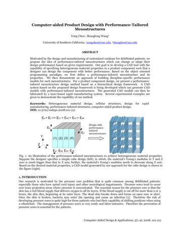
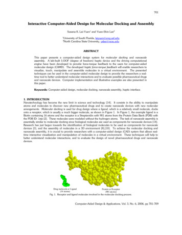
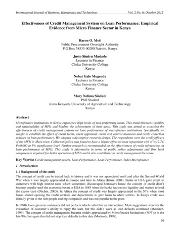
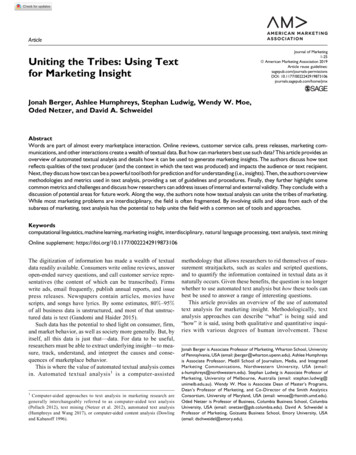
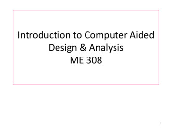
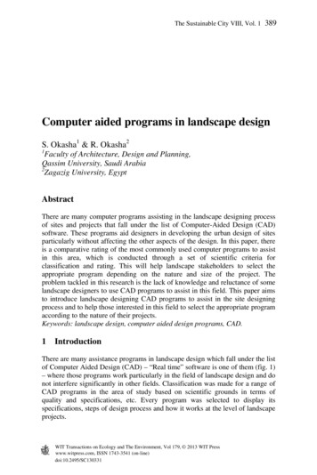
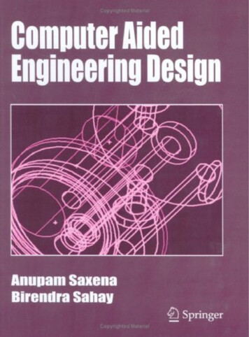
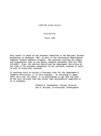
4manipulation. It has resulted in a body of knowledge which is quickly finding its w a y into u se by the m anyindustries that h a ve need for such techniques. M ost recently, the developm ent of an experim ental systemcalled A l p h a -1 h as been undertaken in an effort to com bine in a single system both high quality com putergraph ics and freeform su rface representation and design. T h e system is b ased on n ew m athem aticaltheo ry (discrete splines) and com putational algorithms (O slo Algorithm) for dealing with sm ooth surfaceform s [4, 22], T h e results of this year-old im plementation effort are illustrated in the following figures.T h e first figure is a picture of an aircraft bulkhead w hich w a s produced using the A l p h a -1 modellingsystem . It is intended to d em onstrate that this approach can successfully model a part involving bothcom plex aerod ynam ic sh ap es, like the side which is derived from the actual skin geom etry of the airplaneengine strut, and sim ple geom etry like the pocketing.It also illustrates that one can d erive high qualitycom puter graphics im ages directly from the spline geom etry m odel itself without using a specialperm anent and s ep a ra te graphics model. It is felt that very subtle and faithful illumination m odels canproduce visual cu e s that are valu ab le to the designer.C olor can be used a s an added dim ension forcom m unicating m anufacturing information, as is portrayed here.T h e second picture illustrates that the approach taken in the A l p h a . 1 system supports thecom putations asso ciated with boolean operations like intersections of two arbitrary surfaces. A furtherconclusion from th ese pictures is that the normal surface calculations required for a high quality renderingof this part, and the calculations required for intersections provide the essen tial information for com putingdirect N C descriptions of the part.T h e enlargem ent re veals that the m ethods used in rendering do notd eg rad e on closeups, s in ce the derived graphics d atab ase is ep h em eral and em ployed only to producethe current im age. This is an unusual asp ect of graphics modelling system s. T h e third figure sh o w s theintersection curve of the cutting surface traced out on the bulkhead, and indicates that the parts would notreadily m ate if they w e re m ad e of rigid materials.T o our best know ledge these pictures of the bulkhead dem onstrate a unique capability in ageom etric modelling approach, for they com bine high quality raster graphics together with both freeformand relatively sim ple su rfa ce s within the context of a single com puter model.will be generalized to g en erate line drawing im ages as well.In the future th ese m ethods3D visualization c a n be en h an ced with the developm ent of new hard w are d evices. At the Universityof U tah work is being conducted on the design and developm ent of a 3D viewing terminal which em ploysa vibrating mirror to g en erate a true 3D (virtual) im age [1]. T h e potential of a practical 3D view ing d eviceapplied to design is evident, although considerable re search in developing the display appropriatealgorithms is n e c e ss a ry to satisfy the n eed s of com puter aided design. This is part of the re sea rch whichis being proposed under this program: the coordination of the work in com puter aided geom etric designwith the 3D view ing term inal.It is felt that m any of the rendering principles and algorithms used inproducing the bulkhead pictures can be applied to develop related algorithms for the 3D V iew er.Current Departmental VLSI Circuit Design ResearchT h e departm ent’s work on the design of v e ry large s c a le integrated circuits concentrates on twoa re a s : the developm ent of novel circuits suggested by other research projects in the departm ent, andim provem ents to the tools and techn iqu es for efficiently developing custom integrated circuits.Circuittechnologies em ployed include N M O S , C M O S , and l2L, with m any of the circuits designed beingfabricated either in the U niversity’s H ed co M icroelectronics Laboratory (d escrib ed later in this proposal) orby outside facilities.P a c k a rdCircuit design facilities include a C om puterVision d esign er system , a Hewlett-3000 com puter system ,andmost of the availab leICdesignsoftware,runningon thedepartm ental com puter system s.Circuits under d evelop m ent include a specialized p rocessor running the C O R D IC trigonom etricalgorithm, which a graduate student under the direction of Kent Sm ith hasim plem ented in a variety offorms, including both clocked and asynchronou s versions.A project headed by A lan D avis isim plem enting a set of self timed [23], bit sliced m icro-sequencer parts. T h e s e include a soft controller,
ULl U n i v e r s i t yofC o m p u t e rA i r c r a f tb u l k h e a ds e p a r a t eN / Cp a r tm a c h i n i n gU t a hS c i e n c em o d e l l e da n dr e n d e r e du s i n gA l p h a1s y s t e m .C o l o r si n d i c a t er e q u i r e dt a s k s .C SO 1 B
mi un i v e r s i t yC o m p u t e rofU t a hS c i e n c eC SO S S
LtL) U n i v e r s i t yC o m p u t e rofU t a hS c i e n c eC S0 2 2
8co m p arab le to the A d van ced M icro D e vice s 2911 seq u encer, m em ory interface, and sub m ach ine control.Theseunitscom m unicateusingafour cyclerequest-acknow ledgeprotocolandarecom pletelyasyn ch ron ou s with respect to other system parts.W o rk in also proceeding on the im plementation of a type of text scanning processor, based on thepartitioned finite state autom aton [12] d evelop ed by L e e H ollaar and R o g e r Haskin, one of his formerg radu ate students. T h e P F S A provides all the capabilities of a conventional finite state recognizer andh as extensions to aid in m atching patterns which include tokens indicating that an arbitrary ch a racter orstring of characters can o ccu r in a given location.It can be readily im plem ented and em ployed a s asp ecial p rocessor attached to a disk m em ory system , sin ce it consists of a num ber of identical ch a racterm atchers, ea ch com prising about 5 kilobits of m em ory and a minimal am ount of random logic, andcap ab le of performing its com parison s in less than the ch a racter d elivery time of a normal disk drive.O ther circuits h a ve been d esigned and fabricated a s test circuits or a s part of our cou rse s e q u e n c e inintegrated circuits.M ost of the re search on V L S I circuits within the departm ent is con cern ed with the d evelop m ent ofbetter tools for the design of structured integrated circuits. M uch of it consists of im provem ents in them ethodology and d evelop m ent tools for structured logic arrays, and in particular the stored logic array(S L A ).A s described by Patil and W e lc h [21], the S L A is a folded program m able logic array (P L A ) whichcontains flip-flops distributed throughout the array, with arbitrary colum n and row breaks to give multiple,independent, finite state m ach in es on a single integrated circuit. It can be used to im plem ent both controlsections and data handling portions, such a s counters, registers, and adders.S L A circuit design is perform ed by placing logic sym bols on a grid. E a c h logic sym bol correspondsto a predefined cell in the S L A library appropriate for the cho sen logic family, and includes flip-flops, A N Dand O R points in the logic arra y matrix, pullup resistors, feed-throughs, corners, and inverters. E a c hsym bo l’s p lacem ent b e co m e s both the logic description of the circuit and the cell p lacem ent andinterconnection n e c e s s a ry to produce the desired circuit.T he com posite of the circuit can be producedsim ply by substituting the specified com posite description of the cells for their logic sym bols. W o rk is alsobeing done on techniques for mapping the S L A logic sym bols onto gate array chips, rather thancom pletely custom circuits.S e v e r a l design tools h a ve been constructed to aid in the design of.an S L A integrated circuit. T h e s einclude editors to help the d esign er cre ate the n e c e ss a ry logic diagram , running on both theC om puterVision system and the departm ent's D ECsystem -20.Their utility is limited, how ever, b e c a u s eonly two workstations are ava ilab le on the C om puterVision system , s e verely limiting its a c c e s s forre sea rch e rs outside the im m ediate V L S I group.T h e D EC system -20 S L A editor u ses a standard A S C IIC R T display (24 lines of 80 characters), limiting its utility due to the s e v e re ly restricted graphics availab leand the limited size of the display. T h e proposed workstations elim inate both th ese problems.A num ber of sim ulation program s h a ve b een developed or extended by m em bers of the V L S Igroup.T h e s e include a gate-level logic simulator (S IM U L O G ) w hich includes not only the normal logicgates, but a lso P L A s , R A M s and R O M s , and p ass transistors. A modified version of the S P I C E integratedcircuit an alysis program is ava ilab le for checking the real-time perform ance of a circuit. An S L A sim ulatorh as also been d evelop ed to aid in checking a design to a ssu re that it m atches the circuit's specifications.Th is sim ulator d oes a com plete logic simulation of exactly w hat the designer has specified. No translationerrors can o ccu r b e c a u s e the actual m ask generation is m ade from the s a m e specification d a ta b a s e asw a s used for the simulation.O th er work on V L S I design autom ation has concentrated on higher level tools for mapping logicd esign sinto finalICgeom etricd esigns(s h a p e son variouslayerswhichcre ateconnections orcom ponents such a s transistors). R e c e n t technical reports h a ve d iscu ssed a layout modeling lang uag efor structured arrays [7] and a com puter aided design system for placing and connecting ve ry large cells(registers,adders,d atab uses,andinput/output drivers andre ceivers) [20].Anew technique forautom atically mapping asyn ch ro n o u s circuit state diagram s into their final geom etric designs h a s beenproposed by Hollaar, b ased on an im plem entation which h as a flip-flop per state [25]. W h ile it m ay seem
9that this requires considerably m ore com ponents than a conventionally im plem ented asynchronou s circuit,for se q u e n c e rs or control sections, the costs are com parable [14]. T h e technique h as few er restrictionson a c ce p ta b le input behavior than normal fundam ental mode asynchronou s circuits, and h as beenextended to include a F O R K / JO IN parallel execution construct and a subroutine capability.R e s e a rc h isconcentrating on the theory and operation of the basic circuits, the im plem entation of the mappingalgorithm s, and the com puter assisted developm ent of appropriate diagnostic seq u en ces.An effort recently funded by the D efen se A d van ced R e s e a rc h Projects A g en cy, with Elliott O rganicka s principal investigator, is exam ining the mapping of high order lang uag e program s into V L S I structures.T h e lang uag e is a sub set of the A d a programming language recently d eveloped for the Departm ent ofD e fe n s e [5], selected b e c a u s e its con ce pts of program units, p ack ag es, and tasks map e a sily onto anum ber of specialized, intercom m unicating finite state m ach in es w h o se structures can be determ inedfrom the data declarations and operations being performed. Prelim inary, hand-produced m appings of anum ber of sim ple program s h a v e b een performed, and a more com plex program, the Internet Protocolm odule recently adopted as a D oD standard, is being m apped from its A d a im plem entation to lo w er levelsof abstraction.A mapping method from a high level programming lang uag e into V L S I circuits offers a num ber ofdistinct ad van tag es.T h e program specification of an algorithm also provides a sim ulator to a ssu re thealgorithm o p erates correctly, since the program need only be run on a conventional processor.If theprogram m ing lang uag e is w idely used by program m ers, it g uaran tees a broad au dience that canunderstand, criticize, and im prove a circuit’s specification. Furtherm ore, lan g u ag es like A d a offer clearseparation b etw een specification and im plem entation at hierarchically structured levels of abstraction.T h e m odular structure selected by the program m er/designer can serve a s a guide (an d in m any c a s e s , atem p late) for the intended hard w are structure. Thu s, m odels of hardw are organization m ay be related tom odules and lesse r units of the program, and m odels of com m unication b etw een hardw are units arerelated to protocols used by interface m odules and lesser units of programs.
10S u m m a rie so f IndividualP ro p o s e dR e s e a rc hP ro je c tsW e propose to continue and expand on the current work on com puter aided design d iscu ssedab o ve, taking full ad van tag e of a num ber of other projects within the departm ent.In addition to theequipm ent being requested, primarily a num ber of high quality graphics oriented workstations, support isbeing requested for senior research ers, visiting faculty, professional program m ers and technicians, andg radu ate students.T h e s e staff m em bers will be used primarily to develop the n e ce ssa ry supporthard w are and software system s for the C A D research, and to provide bridges betw een the C A D effort andother projects in the departm ent.T h e specific projects being proposed can be divided into three distinct groups:directlyonprojects workingcom puter aided design, extensions to current re se a rch activities to benefit C A D , and projectsfrom within and outside of the Departm ent of C om puter S c ie n c e which will use the C A D system s beingd eveloped.Computer Aided Design Projects,/T h e s e projects represent the major thrust of the proposed research.T h e y represent continuationand expansion of the current departm ental research, taking full ad van tag e of the ad van ce d com puters c ie n c e d evelop m ents of the various support projects.C o m p u te r A id e d 3D S h a p e D e s ig n .(S e n io r Investigator:Rich ard F. R ie sen fe ld ) T h e currentw ork on com puter aided 3D s h a p e design, which is focused around a project called A l p h a 1, will be oneof the prim ary beneficiaries of this grant. T h e graphical workstations to be purchased will rem ove one ofthe m ajor bottlenecks slowing exploitation of the current work: the limited availability, and con seq uen tscheduling problem s, of graphical d evices. T h e current displays (an E v a n s and Suth erland Multi-PictureS y s te m and a Grinnell F ra m e Buffer, being augm ented this sum m er with a M eg ate k 9250 color rastersystem ) a re certainly cap ab le of performing the operations required for the current work, but must beshared not only am ong the A l p h a 1 researchers, but V L S I and other re searchers, and som e classroo mwork.T h e use of lower cost graphical workstations will not only provide better a c c e s s for softw aredevelopm ent, but will allow "graphical com m ents," sim ple pictures and diagram s docum enting how aparticular algorithm works, to be included in program s and docum entation.T h e additional facilities will not only further the softw are developm ent of A l p h a 1, but will alsoprovide a sufficient num ber of stations so that considerable experim entation and ex p erience c a n beaccu m ulated in using the design stations on actual design projects.At present, a n y practical modellingex erc is e s com pete with syste m s developm ent time since there is only one such com puting resou rce forthis activity.W e also propose to substantially expand the scop e of A l p h a 1 to com plete m any of the a re a s ofd evelop m ent n e c e ss a ry to m ake it a viab le system in actual practice.At this point it h a s dem onstratedan d validated the basic ap p roach of using discrete splines a s a central model for geom etry an d highquality rendering.N ow w e will extend our work in deriving analytic m odels from the central geom etrym odel, and to developing direct num eric control program s which are n e c e s s a ry to m anufacture m any ofthe parts w hich might be m odelled by A l p h a 1. Although previous attem pts to u se techniques su ch assym bolic com putation to analytically m anipulate and derive ad van ce d surface representations h a ve shownprom ise, personnel to work on the interfacing of th e s e two projects h a ve been limited. Sim ilarly, w ork willbe d one on the d evelop m ent of suitable d a ta b a s e s and im proved softw are tools to aid in creating highquality softw are and transporting it to a variety of system s so that ot
computer-aided design system has to provide quite different kinds of support during the different phases of design, which is part of the difficulty in trying to bring computers into this intrinsically human act of creativity. In the earliest phases of design, a computer