Transcription
Series MI/MIHGas BoilersInstallation,Operation &MaintenanceManual
TABLE OF CONTENTSTABLE OF CONTENTSUSING THIS MANUAL1A. INSTALLATION SEQUENCE . . . . . . . . . . . . .1B. SPECIAL ATTENTION BOXES . . . . . . . . . . .11. PREINSTALLATION2A. ACCESSIBILITY CLEARANCES . . . . . . . . . .2B. CLEARANCE FROM COMBUSTIBLECONSTRUCTION . . . . . . . . . . . . . . . . . . . . .2C. AIR FOR COMBUSTION ANDVENTILATION . . . . . . . . . . . . . . . . . . . . . . .2D. LIQUEFIED PETROLEUM (LP) GAS . . . . . . .4E. INSTALLATION SURVEY . . . . . . . . . . . . . . .4F. PLANNING THE LAYOUT . . . . . . . . . . . . . . .42. BOILER SET-UP53. WATER PIPING AND CONTROLS6A. BOILER SUPPLY AND RETURN . . . . . . . . . .6B. SAFETY RELIEF VALVE . . . . . . . . . . . . . . . .7C. PIPING FOR ZONED SYSTEMS . . . . . . . . . .8D. EXPANSION TANK . . . . . . . . . . . . . . . . . . . .9E. INDIRECT-FIRED WATER HEATER . . . . . . . .9F. FREEZE PROTECTION . . . . . . . . . . . . . . . . .94. VENTING10A. INTEGRAL DRAFT HOOD . . . . . . . . . . . . .10B. VENT DAMPER INSTALLATION –GENERAL . . . . . . . . . . . . . . . . . . . . . . . . . .10C. VENT PIPING AND CHIMNEY . . . . . . . . . .11D. BOILER REMOVAL FROM COMMONVENTING SYSTEM . . . . . . . . . . . . . . . . . . .125. GAS PIPING136. ELECTRICAL15A. WIRING . . . . . . . . . . . . . . . . . . . . . . . . . . .15B. ZONED SYSTEM WIRING . . . . . . . . . . . . .15C. CONTROLS . . . . . . . . . . . . . . . . . . . . . . . .15D. SEQUENCE OF OPERATION . . . . . . . . . . .167. START-UP PROCEDURES20A. COMPLETING THE INSTALLATION . . . . . .20B. CONTROL DESCRIPTIONS . . . . . . . . . . . . .24C. ADJUSTMENT OF GAS PRESSUREREGULATOR . . . . . . . . . . . . . . . . . . . . . . .24D. ADJUSTMENT OF PILOT GAS FLOW . . . .24E. CHECKING BURNER INPUT . . . . . . . . . . . .24F. CHECK-OUT PROCEDURE . . . . . . . . . . . . .258. TROUBLESHOOTING26A. SHUT-DOWN CAUSED BY PILOT OUTAGE,BLOCKED VENT SHUT-OFF SWITCH ORFLAME ROLL-OUT SAFETY SHUT-OFFSWITCH . . . . . . . . . . . . . . . . . . . . . . . . . . .26B. TROUBLESHOOTING GUIDES . . . . . . . . . .269. MAINTENANCE29A. GENERAL . . . . . . . . . . . . . . . . . . . . . . . . . .29B. DAILY (WITH BOILER IN USE) . . . . . . . . . .29C. WEEKLY (WITH BOILER IN USE) . . . . . . . .29D. MONTHLY (WITH BOILER IN USE) . . . . . . .29E. ANNUALLY (BEFORE START OF HEATINGSEASON) . . . . . . . . . . . . . . . . . . . . . . . . . .3010. BOILER DIMENSIONS & RATINGS3111. REPAIR PARTS32A. BASE/COMBUSTIBLE FLOOR PAN . . . . . . .32B. MANIFOLD/GAS TRAIN . . . . . . . . . . . . . . .34C. BLOCK/DRAFT HOOD . . . . . . . . . . . . . . . .36D. JACKET . . . . . . . . . . . . . . . . . . . . . . . . . . .38E. CONTROLS/CIRCULATOR/VENTDAMPER . . . . . . . . . . . . . . . . . . . . . . . . . .40
USING THIS MANUALUSING THIS MANUALA. INSTALLATION SEQUENCEFollow the installation instructions provided in thismanual in the order shown. The order of theseinstructions has been set in order to provide the installerwith a logical sequence of steps that will minimizepotential interferences and maximize safety duringboiler installation.B. SPECIAL ATTENTION BOXESThroughout this manual you will see special attentionboxes intended to supplement the instructions and makespecial notice of potential hazards. These categoriesmean, in the judgment of Peerless Heater Company:DANGERIndicates a condition or hazard which will causesevere personal injury, death or major propertydamage.WARNINGIndicates a condition or hazard which may causesevere personal injury, death or major propertydamage.CAUTIONIndicates a condition or hazard which will or cancause minor personal injury or property damage.NOTICEIndicates special attention is needed, but not directlyrelated to potential personal injury or propertydamage.1
PREINSTALLATION1. PREINSTALLATIONRead carefully, study these instructions before beginning work.This boiler must be installed by a qualified contractor.The boiler warranty can be voided if the boiler is not installed, maintained and serviced correctly.NOTICEThe equipment must be installed in accordance with those installation requirements of the authority havingjurisdiction or, in the absence of such requirements, to the current edition of the National Fuel Gas Code, ANSIZ223.1/NFPA 54.Where required by the authority having jurisdiction, the installation must conform to American Society ofMechanical Engineers Safety Code for Controls and Safety Devices for Automatically Fired Boilers, ASME CSD-1.A. ACCESSIBILITY CLEARANCESInstall boiler not less than 24″ between the left side, top,and front of the boiler and adjacent wall or otherappliance, when access is required for servicing.B. CLEARANCE FROM COMBUSTIBLECONSTRUCTIONThe design of this boiler is certified for alcove installationwith the following clearances:1. 6″ between sides and combustible construction.2. 24″ between top of jacket and combustibleconstruction.3. 6″ between draft hood and combustibleconstruction.4. 6″ between vent pipe and combustible construction.5. 10″ between rear of jacket and combustibleconstruction.WARNINGDo not install this boiler on combustible flooringunless it is installed on a special combustible floorpan provided by Peerless Heater Company. Boilerinstallation on combustible flooring without thespecial pan is a fire hazard.To order combustible floor pan, use the 5-digit stockcodes listed in Section 11A of this manual.WARNINGDo not install this boiler on carpeting. Boilerinstallation on carpeting is a fire hazard. Install thisboiler on non-combustible flooring or use acombustible floor pan to install this boiler on othernon-carpeted flooring.C. AIR FOR COMBUSTION ANDVENTILATION1. Provide adequate facilities for combustion andventilation air in accordance with Section 5.3, Air forCombustion and Ventilation, National Fuel GasCode, or applicable provisions of the local buildingcode. Subsections 2 through 6 below are based onNational Fuel Gas Code requirements.2. Definitions:Unconfined Space: a space whose volume is notless than fifty (50) cubic feet per 1000 Btu/hr of thetotal input rating of all appliances installed in thatspace. Rooms communicating directly with the spacein which the appliances are installed, throughopenings not furnished with doors, are consideredpart of the unconfined space.Unusually Tight Construction: Constructionwhere:a. Walls and ceilings exposed to the outsideatmosphere have a continuous water vaporretarder with a rating of 1 perm or less withopenings gasketed or sealed, andb. Weatherstripping has been added on openablewindows and doors, andc. Caulking or sealants are supplied to areas suchas joints around window and door frames,between sole plates and floors, between wallceiling joints, between wall panels, atpenetrations for plumbing, electrical and gaslines, and at other openings.2
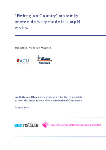
PREINSTALLATION3. Appliances Located in Unconfined Spaces:For installations in unconfined spaces with otherthan unusually tight construction, the supply of airfor combustion and ventilation can usually beconsidered adequate.4. Unusually Tight Construction:For equipment located in buildings of unusually tightconstruction as defined on the previous page,provide air for combustion and ventilation using themethods described in 5a or 5b below.5. Appliances Located in Confined Spaces:a. All air from inside the building: Provide twopermanent openings communicating directly withan additional room or rooms of sufficient volumeso that the combined volume of all spaces meetsthe criteria for an unconfined space. Use the totalinput of all gas utilization equipment installed inthe combined space in making thisdetermination.Figure 1:Air Openings – All Air from IndoorsFigure 2:Air Openings – All Air Directly fromOutdoorsFigure 3:Air Openings – All Air from Outdoorsthrough Vertical DuctsSize each opening with a minimum free area ofone square inch per 1000 Btu/hr. of the totalrating of all gas utilization equipment in theconfined space, but not less than 100 squareinches. Begin with one opening 12 inches fromthe top, and begin the other opening within 12inches of the bottom of the enclosure. See Figure1. Provide air openings with minimumdimensions not less than three (3) inches.b. All air from outside the building. Connect theconfined space with the outdoors in accordancewith methods i) or ii) below. Provide air openingswith minimum dimensions not less than three (3)inches. Where ducts are used, make certain thatthey are the same cross-sectional area as the freearea of the openings to which they connect.i) Provide two permanent openings, onecommencing within 12 inches of the top andone commencing within 12 inches of thebottom of the enclosure. Connect theopenings directly or by ducts, with theoutdoors or spaces (crawl or attic) that freelycommunicate with the outdoors.Where directly communicating with theoutdoors (see Figure 2) or wherecommunicating to the outdoors throughvertical ducts (see Figure 3), size eachopening with a minimum free area of one (1)square inch per 4000 Btu/hr. of total rating ofall equipment in the enclosure.3
PREINSTALLATIONWhere communicating with the outdoorsthrough horizontal ducts, size each openingwith a minimum free area of one (1) squareinch per 2000 Btu/hr. of total input rating ofall equipment in the enclosure. See Figure 4.ii) Where the equipment has clearances of atleast one (1) inch from the sides and backand six (6) inches from the front of theappliance, the code allows one permanentopening, commencing within 12 inches ofthe top of the enclosure. Connect theopening directly with the outdoors or througha vertical or horizontal duct to the outdoorsor spaces (crawl or attic) that freelycommunicate with the outdoors. Size theopening with a minimum free area of onesquare inch per 3000 Btu/hr. of the totalinput rating of all equipment in the enclosure,and not less than the sum of the areas of allvent connectors in the confined space.6. In calculating free area of an opening, take intoaccount the blocking affect of louvers, grilles andscreens. Do not use screens smaller than 1/4” mesh.If the free area is known, use this value in calculatingthe size of the opening required. If it is not known,assume that wood louvers provide 20-25% free area,and metal louvers and grilles provide 60-75% freearea.7. Remove sources of hydrocarbons (bleaches,cleaners, chemicals, sprays, paint removers, fabricsofteners, etc.) from the boiler area. The vaporsgenerated by these substances can contaminate thecombustion air and contribute to shortenedboiler/vent system life.WARNINGLiquefied Petroleum (LP) is heavier than air and maycollect or “pool” in a low area in the event of a leakfrom defective equipment. This gas may then ignite,resulting in a fire or explosion. See the instructionsbelow.D. LIQUEFIED PETROLEUM (LP) GASThe following LP requirements from the UniformMechanical Code, section 304.6, may be in effect inyour geographic area:“Liquefied petroleum gas-burning appliances shallnot be installed in a pit, basement or similar locationwhere heavier-than-air gas might collect. Appliancesso fueled shall not be installed in an above-gradeunder-floor space or basement unless such locationis provided with an approved means for removal ofunburned gas.”4Figure 4:Air Openings – All Air from Outdoorsthrough Horizontal DuctsE. INSTALLATION SURVEYFor new and existing installations, a Water InstallationSurvey is available from Peerless Heater Company. Thesurvey will provide information on how a hot waterboiler works with your specific system and will providean overview of hot water system operation in general.You can also use this survey to locate system problemswhich will have to be corrected. To obtain copies of theWater Installation Survey, contact your Peerlessrepresentative.F.PLANNING THE LAYOUTPrepare sketches and notes of the layout to minimize thepossibility of interferences with new or existingequipment, piping, venting and wiring.
BOILER SET-UP2. BOILER SET-UP1. Provide a sound, level foundation. Locate boiler asnear to the chimney or outside wall as possible andcentralized with respect to the heating system.4. Separate the wood shipping pallet from the boilerbase by removing two (2) hold-down bolts at eachend of the boiler base.2. Locate boiler in front of installation position beforeremoving crate.5. Move boiler into final position. If using combustiblefloor pan, install boiler on pan as outlined in theinstructions included with the pan.3. If using combustible floor pan, position pan onfoundation or flooring.5
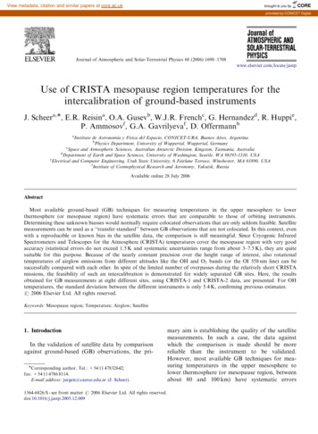
WATER PIPING AND CONTROLS3. WATER PIPING AND CONTROLSA. BOILER SUPPLY AND RETURN1. Size the supply and return to suit the system. Atypical piping arrangement is shown in Figure 5.Refer also to the I B R Installation Guide No. 200and the Peerless Water Survey for additionalguidance during water piping installation.2. Return Piping:a. For boilers equipped with a factory-mountedcirculator, pipe the return to the inlet connectionof the circulator.b. For boilers equipped with a separate, unmountedcirculator, pipe the outlet connection of thecirculator to a tee, provided with a drain valve, atthe 1-1/4 NPT return tapping near the bottom ofthe left section. Pipe the return to the inletconnection of the circulator.Figure 5:6Supply and Return Piping3. Supply Piping:Pipe the supply to the 1-1/2 NPT supply tapping atthe top and rear of the boiler.4. When system return water temperature will be below130 F, pipe the boiler with a bypass arrangement toblend the system return and hot supply to obtain atleast 130 F entering the boiler. For more informationon bypass piping, consult the Peerless Water Survey.5. If desired, install the circulator in the alternatelocation shown in Figure 5. Consult the PeerlessWater Survey for more information on circulatorlocation.
WATER PIPING AND CONTROLS6. Install this boiler so that the gas ignition systemcomponents are protected from water (dripping,spraying, etc.) during appliance operation andservice (circulator replacement, condensate trap,control replacements, etc.).7. If this boiler and distribution system is used inconjunction with a refrigeration system, pipe thechilled medium in parallel with the boiler and installthe proper valve to prevent the chilled medium fromentering the boiler. A drawing illustrating this hookup is provided in Figure 6.8. When the boiler is connected to heating coils locatedin air handling units where they may be exposed torefrigerated air circulation, install flow control valvesor other automatic means to prevent gravitycirculation of the boiler water during the coolingcycle.9. If this boiler is installed above radiation level,provide a low water cutoff device, either as a part ofthe boiler or at the time of boiler installation.Figure 6:Parallel Hook-up with Water ChillerFigure 7:Safety Relief Valve Hook-Up Installationwith Air Elimination in System PipingFigure 8:Safety Relief Valve Hook-Up withAir EliminationB. SAFETY RELIEF VALVE1. Locate safety relief valve and fittings in bagassembly.2. If air elimination is not required at the safety reliefvalve tapping, install valve and piping as shown inFigure 7.3. For air elimination at the safety relief valve tapping,install valve and piping as shown in Figure 8.CAUTIONPipe the discharge of safety relief valve to preventinjury in the event of pressure relief. Pipe thedischarge to a drain. Provide piping that is the samesize as the safety relief valve outlet.7
WATER PIPING AND CONTROLSC. PIPING FOR ZONED SYSTEMS1. See Figures 9 and 10 for basic zoned system layouts.2. Run each zone pipe down then up to zone toprevent air accumulation in piping.3. If required, provide means to isolate and drain eachzone separately.Figure 9:Zone Piping with Zone ValvesFigure 10: Zone Piping with Circulators8
WATER PIPING AND CONTROLSD. EXPANSION TANKF.For new or existing systems that must be freezeprotected:1. Consult the tank manufacturer’s instructions forspecific information relating to tank installation. Sizethe expansion tank for the required system volumeand capacity. See Table 8 in Section 10 for boilerwater capacity.2. Expansion tanks are available with built-in fill valvesand check valves for reducing supply water pressureand maintaining minimum system pressure. Checkthe design features of the tank and provide valves asnecessary.FREEZE PROTECTIONWARNINGUse only inhibited propylene glycol solutions of up to50% by volume with water. Ethylene glycol is toxicand can attack gaskets and seals used in hydronicsystems.Refer back to Figure 5 for typical expansion tank piping.E. INDIRECT-FIRED WATER HEATERIf the boiler is to be used in conjunction with an indirectfired water heater, refer to Figure 11 for typical piping.Follow the instructions provided by the water heatermanufacturer. Pipe the water heater as a separate zone.1. Glycol in hydronic applications is speciallyformulated for this purpose. It includes inhibitorswhich prevent the glycol from attacking metallicsystem components. Make certain that the systemfluid is checked for the correct glycol concentrationand inhibitor level.2. The anitfreeze solution should be tested at least oncea year and as recommended by the anitfreezemanufacturer.3. Antifreeze solutions expand more than water. Forexample, a 50% by volume solution expands 4.8%in volume for a temperature increase from 32 F to180 F, while water expands 3% with the sametemperature rise. Allowance must be made for thisexpansion in system design.4. For more information, consult the Peerless WaterInstallation Survey and the antifreeze manufacturer.Figure 11: Typical Piping with Indirect-Fired Water Heater9
VENTING4. VENTINGA. INTEGRAL DRAFT HOOD1. The MI/MIH boiler is equipped with a built-in drafthood. This device is designed to:a. provide for the ready escape of flue gases fromthe boiler in the event of no draft.b. prevent a backdraft from entering the boiler.B. VENT DAMPER INSTALLATION –GENERAL1. Do not use one vent damper to control two or moreheating appliances. See Figure 12.2. Follow these and the installation instructions that areincluded with the vent damper. Observe the cautionsand warnings that accompany all instructions.c. control stack draft during operation.These tasks are accomplished without the extraheight requirements of a separate draft hood.2. The draft hood relief opening is the large rectangularpassage at the front of the boiler. Make certain thatthere are no obstructions to airflow in front of thisopening.3. A vent safety shut-off switch is located within thedraft relief opening to shut off the boiler in case of ablocked vent condition. See Section 7B for detailsregarding this device. See Figure 16 in Section 6(Electrical) for spill switch location.4. The vent damper can be mounted directly onto theround draft hood outlet (vent connector) on top ofthe boiler, or in vent piping close to the boiler. Seethe Vent Damper Installation Instructions below.Figure 12: Venting Multiple Appliances103. Make certain that minimum clearances provided inthe vent damper manufacturer’s instructions aremaintained and that adequate space is available fordamper access and service.4. Orient the damper operator to facilitate connectionof the harness with the vent damper and boiler. Noteflue gas flow arrow on vent damper and orient asrequired. For installation with damper mounted invertical position, see Figure 13. For installation withdamper mounted in horizontal position, mount theunit as shown in Figure 14 to avoid excessive heaton the operator or condensation drips into theoperator.
VENTINGC. VENT PIPING AND CHIMNEY1. Install vent piping in accordance with Part 7, Ventingof Equipment, National Fuel Gas Code, ANSIZ223.1/NFPA 54 or applicable provisions of the localbuilding codes.2. Inspect the existing chimney and lining for structuralsoundness, corrosion and perforations. Repair asnecessary.3. Install vent pipe to slope upward at least 1/4” perlineal foot between the draft hood outlet and thechimney.4. Before connection of joints, inspect the vent pipeinterior for foreign objects such as tools, equipment,rags, etc. and remove if present.5. Insert vent pipe into but not beyond the inside wallof the chimney flue.6. Do not connect vent connectors serving appliancesvented by natural draft into any portion ofmechanical draft systems operating under positivepressure.7. Support horizontal portions of the venting system toprevent sagging by use of metal strapping orequivalent means. Locate supports at no more thanfour (4) foot intervals.Figure 13: Venting with Vent Damper in Vertical PositionFigure 14: Venting with Vent Damper in Horizontal Position11
VENTINGD. BOILER REMOVAL FROM COMMONVENTING SYSTEMAt the time of removal of an existing boiler, follow thesesteps with each appliance remaining connected to thecommon venting system placed in operation, while theother appliances remaining connected to the commonventing system are not in operation:a. Seal any unused openings in the common ventingsystem.b. Visually inspect the venting system for proper sizeand horizontal pitch and determine there is noblockage or restriction, leakage, corrosion and otherdeficiencies which could cause an unsafe condition.c. Insofar as is practical, close all building doors andwindows and all doors between the space in whichthe appliances remaining connected to the commonventing system are located and other spaces of thebuilding. Turn on any clothes dryers and anyappliance not connected to common venting system.Turn on any exhaust fans, such as range hoods andbathroom exhausts, so they will operate at maximumspeed. Do not operate a summer exhaust fan. Closefireplace dampers.12d. Place in operation the appliance being inspected.Follow the lighting instructions. Adjust thermostat soappliance will operate continuously.e. Test for spillage at the draft hood relief opening after5 minutes of main burner operation. Use the flameof a match or candle, or smoke from a cigarette,cigar, or pipe.f. After it has been determined that each applianceremaining connected to the common venting systemproperly vents when tested as outlined above, returndoors, windows, exhaust fans, fireplace dampers andany other gas-burning appliance to their previousconditions of use.g. Any improper operation of the common ventingsystem should be corrected so that the installationconforms with the National Fuel Gas Code. Whenresizing any portion of the common venting system,the common venting system should be resized toapproach minimum size as determined using theappropriate tables in Part 11 of the National FuelGas Code.
GAS PIPING5. GAS PIPING1. Size and install the gas supply piping properly inorder to provide a supply of gas sufficient to meetthe maximum demand without undue loss ofpressure between the meter and the boiler.2. Determine the volume of gas to be provided to theboiler in cubic feet per hour. To obtain this value,divide the Btu per hour rating (on the boiler ratingplate) by the heating value of the gas in Btu percubic feet. Obtain the heating value of the gas fromthe gas supplier. As an alternative, use Table 1, 2 or3 on the next page to obtain the volume of gas to beprovided to the boiler.3. Use the value obtained above as the basis for pipingsizing. Size the gas piping in accordance with Table4. Consult the National Fuel Gas Code for othersizing options.4. Locate the drop pipe adjacent to, but not in front ofthe boiler.5. Install a sediment trap. See Figure 15. Locate a teein the drop pipe at same elevation as the gas inletconnection to the boiler. Extend the drop pipe to apipe cap.6. Install a ground joint union ahead of the gas controlassembly to permit servicing of the control. Somelocal codes require an additional service valve whenusing the combination gas controls. If your coderequires such a valve, a suggested location is shownin Figure 15.WARNINGUse a pipe joint sealing compound that is resistant tothe action of liquefied petroleum gas. A non-resistantcompound may lose sealing ability in the presence ofthis gas, resulting in a gas leak and fire or explosionpotential.7. Check piping for leaks.Use an approved gas detector, a non-corrosive leakdetection fluid or other leak detection method. Ifleaks are found, turn off all gas flow and repair asnecessary.Figure 15: Gas Connection to Boiler8. Disconnect the boiler and its individual shut-off valvefrom the gas supply piping system during anypressure testing of that system at test pressure inexcess of 1/2 psig (3.5 kPa).CAUTIONDo not subject the gas valve to more than 1/2 psipressure. Doing so may damage the valve.Isolate the boiler from the gas supply piping systemby closing its individual service valve during anypressure testing of the gas supply piping system attest pressure equal to or less than 1/2 psig (3.5 kPa).9. Minimum permissible supply pressure for purposes ofinput adjustment (Inches Water Column):MI-09 Standing Pilot Natural Gas5.2″All other MI/MIH Natural Gas5.0″All MI LP Gas11.0″Maximum permissible supply pressure to the boiler(Inches Water Column):All MI/MIH Natural Gas13.5″All MI LP Gas13.5″WARNINGWhen checking for leaks, do not use matches,candles, open flames or other methods that provide asource of ignition. This can ignite a gas leak,resulting in fire or explosion.13
GAS PIPINGTable 1:MI Boiler – Natural GasModelInput(Cubic 75195227.5260Based on 1000 Btu/Cubic Ft.Table 2:MI Boiler – LP GasModelInput(Cubic 891104Based on 2500 Btu/Cubic Ft.Table 3:MIH Boiler – Natural GasModelInput(Cubic Ft/Hr)MIH-03MIH-04MIH-05MIH-066597.5130162.5Based on 1000 Btu/Cubic Ft.Table 4:Pipe CapacityCapacity of pipe of different diameters and lengths in cu. ft. perhour with pressure drop of 0.3 in. and specific gravity of 0.60.No allowance for an ordinary number of fittings is required.PipeLengthFeet³ ₄″″Pipe1″″Pipe1¹ ₄″″Pipe1¹ 610Multipliers to be used with the above table when thespecific gravity of the gas is other than 0.60:Specific Gravity . . .0.50.550.600.65Multiplier . . . . . . . .1.10 1.041.000.962140.700.926
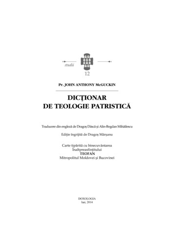
ELECTRICAL6. ELECTRICALInstall all electrical wiring in accordance with the National Electrical Code and local requirements.NOTICEThis unit when installed must be electrically grounded in accordance with the requirements of the authorityhaving jurisdiction or, in the absence of such requirements, with the current edition of the National ElectricalCode, ANSI/NFPA 70.A. WIRINGC. CONTROLS1. See Figure 16 for location of wiring and controls.Use Figures 17 and 18 to connect the boiler to apower supply and to connect components to theboiler.2. Connect the boiler by a separate, permanently liveelectrical supply line with a fused switch.3. Connect the vent damper harness to the polarizedconnector in the boiler vestibule as shown inFigure 16.4. Adjust the thermostat heat anticipator to 0.2 Amp.1. For proper location of controls and accessories referto Figure 16 and Section 11.2. See the attached control sheets for specific detailsregarding the installation of the various controls.3. This boiler is supplied with safety devices in additionto the limit. For a description of these devices andhow they work to ensure the safe operation of theboiler, see Section 7B.4. If the circulator is mounted in the supply piping,provide longer wiring harness as required.B. ZONED SYSTEM WIRINGSee Figure 20 for typical wiring with zone valves. SeeFigure 21 for typical wiring with zone circulators. Whenwiring a zoned heating system, follow all applicablecodes, ordinances and regulations.NOTICEDo not power zone valves directly from the boilerlimit. Doing so will greatly reduce the life of thetransformer. Use a separate transformer sized tohandle the total of all zone valve electrical loads.Figure 16: Wiring, Controls and Safety Devices15
ELECTRICALFigure 17: Wiring and Connection Diagram – Standing Pilot (Continuous Ignition)D. SEQUENCE OF OPERATION1. Standing Pilot (See Figure 17 above)a. The vent damper is continuously powered. On acall for heat, limit relay R is energized, whichenergizes: the circulator (when used) through contactR1, andthe vent damper operator through contact R2,provided that the high-limit switch isclosed.The vent damper operator opens the damper.b. Once the damper is proven open, the gas valveenergizes, provided that all of the followingconditions are met: 16the pilot thermocouple is proving flamethe blocked vent switch is closed, andthe flame rollout switch is closed.Pilot flame is monitored through the pilotthermocouple. If pilot flame is lost during a callfor heat, main and pilot gas flow will be shut off.The valve must then be manually reset byfollowing the Lighting Instructions mounted onthe jacket panel and included in Section 7 of thismanual.c. When the call for heat ends: Limit relay R de-energizes, which openscontacts R1 and R2. The circulator shuts down. The gas valve de-energizes. The vent damper closes.d. If temperature exceeds limit setting, main burnersshut off and circulator continues to operate.
ELECTRICALFigure 18: Wiring and Connection Diagram – Intermittent Ignition2. Intermittent Ignition (see Figure 18 above)a. The vent damper is continuously powered. On acall for heat, limit relay R is energized, whichenergizes: the circulator (when used) through contactR1, andthe vent damper operator through contact R2,provided that the high-limit aquastat switch isclosed.The damper operator opens the vent damper.b. Once the damper is proven open, the ignitioncircuit within the gas valve energizes, providedthat all of the following conditions are met: the blocked vent switch is closed, and the flame rollout switch is closed.c. When the call for heat ends: Limit relay R de-energizes, which openscontacts R1 and R2. The circulator shuts down. The gas valve de-energizes. The vent d
Boiler installation on carpeting is a fire hazard. Install this boiler on non-combustible flooring or use a combustible floor pan to install this boiler on other non-carpeted flooring. WARNING Do not install this boiler on combustible flooring unless it is installed on a special combustible floor pan provided by Peerless Heater Company. Boiler