Transcription
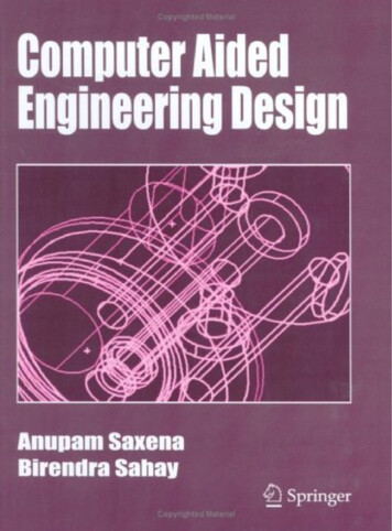
Computer Aided Engineering Design
Computer AidedEngineering DesignAnupam Saxena 䊐 Birendra SahayDepartment of Mechanical EngineeringIndian Institute of Technology Kanpur, IndiaSpringerAnamaya
A C.I.P. catalogue record for the book is available from the Library of CongressISBN 1-4020-2555-6 (HB)Copublished by Springer233 Spring Street, New York 10013, USAwith Anamaya Publishers, New Delhi, IndiaSold and distributed in North, Central and South America by Springer233 Spring Street, New York, USAIn all the countries, except India, sold and distributed by SpringerP.O. Box 322, 3300 AH Dordrecht, The NetherlandsIn India, sold and distributed by Anamaya PublishersF-230, Lado Sarai, New Delhi-110 030, IndiaAll rights reserved. This work may not be translated or copied in whole or in part withoutthe written permission of the publisher (Springer Science Business Media, Inc., 233Spring Street, New York, NY 10013, USA), except for brief excerpts in connection withreviews or scholarly adaptation, computer software, or by similar or dissimilar methodologynow known or hereafter developed is forbidden.The use in this publication of trade names, trademarks, service marks and similar terms,even if they are not identified as such, is not to be taken as an expression of opinion asto whether or not they are subject to proprietary rights.Copyright 2005, Anamaya Publishers, New Delhi, India9 87654321springeronline.comPrinted in India.
To my parents, all my teachers and for my son Suved when he grows upAnupam SaxenaTo my mother, Charushila Devi, an icon of patienceTo my eldest brother, Dhanendra Sahay who never let me feel the absence of my fatherTo my brother, Dr. Barindra Sahay for initiating me into the realm of mathematicsTo my teachers at McMaster University and University of WaterlooTo my wife, Kusum, children Urvashi, Menaka, Pawan and the little fairyRadhika (granddaughter)Birendra Sahay
ForewordA new discipline is said to attain maturity when the subject matter takes the shape of a textbook.Several textbooks later, the discipline tends to acquire a firm place in the curriculum for teachingand learning. Computer Aided Engineering Design (CAED), barely three decades old, isinterdisciplinary in nature whose boundaries are still expanding. However, it draws its core strengthfrom several acknowledged and diverse areas such as computer graphics, differential geometry,Boolean algebra, computational geometry, topological spaces, numerical analysis, mechanics ofsolids, engineering design and a few others. CAED also needs to show its strong linkages withComputer Aided Manufacturing (CAM). As is true with any growing discipline, the literature iswidespread in research journals, edited books, and conference proceedings. Various textbooks haveappeared with different biases, like geometric modeling, computer graphics, and CAD/CAM overthe last decade.This book goes into mathematical foundations and the core subjects of CAED without allowingitself to be overshadowed by computer graphics. It is written in a logical and thorough manner foruse mainly by senior and graduate level students as well as users and developers of CAD software.The book covers(a) The fundamental concepts of geometric modeling so that a real understanding of designingsynthetic surfaces and solid modeling can be achieved.(b) A wide spectrum of CAED topics such as CAD of linkages and machine elements, finiteelement analysis, optimization.(c) Application of these methods to real world problems.In a new discipline, it is also a major contribution creating example problems and theirsolutions whereby these exercises can be worked out in a reasonable time by students andsimultaneously encouraging them to tackle more challenging problems. Some well tried out projectsare also listed which may enthuse both teachers and students to develop new projects. The writingstyle of the book is clear and thorough and as the student progresses through the text, a greatsatisfaction can be achieved by creating a software library of curve, surface, and solid modelingmodules.Dr. Anupam Saxena earned his MSME degree in 1997 at the University of Toledo, Ohio, USA.I am familiar with his work on a particularly challenging CAED problem for his thesis. Heearned his Ph.D. degree from the University of Pennsylvania, USA and became a faculty memberat IIT Kanpur in 2000. Dr. Sahay was Professor at IIT Kanpur where he performed research and
viiiFOREWORDteaching in design related fields for over the past 32 years after having earned his Ph.D. from theUniversity of Waterloo, Canada. This textbook is a result of over ten years of teaching CAED byboth authors.The topics covered in detail in this book will, I am sure, be immensely helpful to teachers, students,practitioners and researchers.Steven N. Kramer, PhD, PEProfessor of Mechanical and Industrial EngineeringThe University of Toledo, Toledo, Ohio
PrefaceThe development of computer aided engineering design has gained momentum over the last threedecades. Computer graphics, geometric modeling of curves, surfaces and solids, finite element method,optimization, computational fluid flow and heat transfer—all have now taken roots into the academiccurricula as individual disciplines. Several professional softwares are now available for the design ofsurfaces and solids. These are very user-friendly and do not require a user to possess the intricatedetails of the mathematical basis that goes behind.This book is an outcome of over a decade of teaching computer aided design to graduate andsenior undergraduate students. It emphasizes the mathematical background behind geometric modeling,analysis and optimization tools incorporated within the existing software. Much of the material on CAD related topics is widely scattered in literature. This book isconceived with a view to arrange the source material in a logical and comprehensive sequence,to be used as a semester course text for CAD. The focus is on computer aided design. Treatment essential for geometric transformations,projective geometry, differential geometry of curves and surfaces have been dealt with indetail using examples. Only a background in elementary linear algebra, matrices and vectorgeometry is required to understand the material presented. The concepts of homogeneous transformations and affine spaces (barycentric coordinatesystem) have been explained with examples. This is essential to understand how a solid orsurface model of an object can escape coordinate system dependence. This enables a distortionfree handling of a computer model under rigid-body transformations. A viewpoint that free-form solids may be regarded as composed of surface patches whichinstead are composed of curve segments is maintained in this book, like most other texts onCAD. Thus, geometric modeling of curve segments is discussed in detail. The basis of curvedesign is parametric, piecewise fitting of individual segments of low degree into a compositecurve such that the desired continuity (position, slope and/or curvature) is maintained betweenadjacent segments. This reduces undue oscillations and provides freedom to a designer to alterthe curve shape. A generic model of a curve segment is the weighted linear combination ofuser-specified data points where the weights are functions of a normalized, non-negativeparameter. Further, barycentricity of weights* makes a curve segment independent of thecoordinate system and provides an insight into the curve’s shape. That is, the curve lies within* Weights are all non-negative and for any value of the parameter, they sum to unity.
xPREFACEthe convex hull of the data points specified. The associated variation diminishing propertysuggests that the curve’s shape is no more complex than the polyline of the control pointsitself. In other words, a control polyline primitively approximates the shape of the curve. ForBézier segments, barycentricity is global in that altering any data point results in overall shapechange of the segment. For B-spline curves, however, weights are locally barycentric allowingshape change only within some local region. Expressions for weights, that is, Bernsteinpolynomials for Bézier segments and B-spline basis functions for B-spline curves are derivedand discussed in detail in this book and many examples are presented to illustrate curvedesign. With the design of free-form curve segments accomplished, surface patches can be obtainedin numerous ways. With two curves, one can sweep one over the other to get a sweep surfacepatch. One of the curves can be rectilinear in shape and represent an axis about which thesecond curve can be revolved to get a patch of revolution. One can join corresponding pointson the two curves using straight lines to generate a ruled surface. Or, if cross boundary slopeinformation is available, one can join the corresponding points using a cubic segment to geta lofted patch. More involved models of surface patches are the bilinear and bicubic Coon’spatches wherein four boundary curves are involved. Eventually, a direct extension of Bézierand B-spline curves is their tensor product into respective free-form Bézier and B-splinesurface patches. These surface patches inherit the properties from the respective curves. Thatis, the surface patch lies within the control polyhedron defined by the data points, and that thepolyhedron loosely represents the patch shape. The aforementioned patches are derived anddiscussed in detail with examples in this book. Later, methods to model composite surfacesare discussed. The basis for solid modeling is the extension of Jordon’s curve theorem which states that aclosed, simply connected** (planar) curve divides a plane into two regions; its interior and itsexterior. Likewise, a closed, simply connected and orientable surface divides a three-dimensionalspace into regions interior and exterior to the surface. With this established, a simple, closedand connected surface constituted of various surface patches knit or glued together at theirrespective common boundaries encloses a finite volume within itself. The union of thisinterior region with the surface boundary represents a free form solid. Any solid modelershould be generic and capable of modeling unambiguous solids such that any set operation(union, intersection or difference) performed on two valid solids should yield another validsolid. With this viewpoint, the concept of geometry is relaxed to study the topological attributesof valid solids. Such properties disregard size (lengths and angles) and study only the connectivityin a solid. With these properties as basis, the three solid modeling techniques, i.e., wireframemodeling, boundary representation method and constructive solid geometry are discussed indetail with examples. Advantages and drawbacks of each method are discussed and it isemphasized that professional solid modelers utilize all three representations depending on theapplication. For instance, wireframe modeling is usually employed for animation as quickrendering is not possible with the boundary representation scheme. Determination of intersection between various curves, surfaces and solids is routinely performedby the solid modelers for curve and surface trimming and blending. Intersection determinationis primarily used in computing Boolean relations between two solids in constructive solid** A closed curve with no self intersection.
PREFACExigeometry. Computational geometry that encompasses a set of algorithms to compute variousrelations like proximity, intersection, decomposition and relational search (e.g., point membershipclassification) between geometric entities is discussed in brief in this book. The working ofthese algorithms is described for polygonal entities with examples for easy understanding ofthe subject matter. Reverse engineering alludes to the process of creating CAD models from existing real lifecomponents or their prototypes. Applications are prolific; some being the generation of customizedfit to human surfaces, designing prostheses, and reconstruction of archaeological collectionsand artifacts. For an engineering component whose original data is not available, a conceptualclay or wood model is employed. A point cloud data is acquired from an existing componentor its prototype using available non-contact or tactile scanning methods. Surface patches arethen locally modeled over a subset of the point cloud to interpolate or best approximate thedata. Reverse engineering is an important emerging application in Computer Aided Design,and various methods for surface patch fitting, depending on the scanning procedure used, arebriefed in this book. Having discussed in detail the geometric modeling aspects in free-form design, this bookprovides an introductory treatment to the finite element analysis (FEM) and optimization, theother two widely employed tools in computer aided design. Using these, one can analyze andalter a design form such that the latter becomes optimal in some sense of the user specifiedobjective. The book discusses linear elastic finite element method using some basic elementslike trusses, frames, triangular and four-node elements. Discussion on optimization is restrictedto some numerical methods in determining single variable extrema and classical KarushKuhn-Tucker necessary conditions for multi-variable unconstrained and constrained problems.Sequential Linear and Quadratic Programming, and stochastic methods like genetic algorithmsand simulated annealing are given a brief mention. The intent is to introduce a student tofollow-up formal courses on finite element analysis and optimization in the curricula.This book should be used by the educators as follows:Students from a variety of majors, e.g., mechanical engineering, computer science and engineering,aeronautical and civil engineering and mathematics are likely to credit this course. Also, studentsmay study CAD at primarily graduate and senior undergraduate levels. Geometric modeling ofcurves, surfaces and solids may be relevant to all while finite element analysis and optimization maybe of interest of mechanical, aeronautical and civil engineering. Discretion of the instructor may berequired to cover the combination of topics for a group of students. Considering a semester course of40 contact hours, a broad breakup of topics is suggested as follows: 1st hour: Introduction to computer aided design3 hours: Transformations and projections15 hours: Free-form curve design9 hours: Surface patch modeling6 hours: Solid modelingThe remaining 6 hours may be assigned as follows: for students belonging to mechanical, aeronauticaland civil engineering, reverse engineering, finite element method and optimization may be introducedand for those in computer science and engineering and mathematics, computational geometry andoptimization may be emphasized.For a group of graduate students taking this course, differential geometry of curves and surfaces
xiiPREFACE(Chapters 3 and 6) may be dealt with in detail. Also, topological attributes of solids may be discussed.For only senior undergraduate students, differential geometry may be covered in brief emphasizingmainly Frenet-Serret relations, Gaussian and Mean curvatures and their importance in determiningthe nature of a surface. Chapters on computational geometry, reverse engineering, FEM and optimizationmay be omitted.Assignments and projects form an important part of this course. Assignments may be tailored ina manner that students get a handle on manual calculations as well as code development for curve andsurface design. A course project may run over a semester or can be in two parts each covering halfthe semester. Some example projects are mentioned in Appendix III.Some examples presented in Chapter 1 on kinematic analysis and spring design pertain to studentsin mechanical engineering. For a generic class, an instructor may prefer to cover curve interpolationand fitting discussed in sections 3.1 and 3.2.The practitioners, i.e., those developing professional software would require much deeperunderstanding of the design principles, mathematical foundations and computer graphics to render arobust Graphical User Interface to the software. This book would help them acquire adequate backgroundknowledge in design principles and mathematical foundations. Those using the software may notrequire a deeper understanding of the mathematical principles. However, design aspects and essentialproperties of curve, surface and solid modeling would be needed to create the design and interpret theresults.Chapters 9 and 10 of this book on computations with geometry and modeling using point cloudshas been contributed by Dr. G. Saravana Kumar, a former Ph.D. Student, Mechanical EngineeringDepartment, IIT Kanpur. His enthusiasm as T.A. in the CAD course has also resulted in several goodprojects.ANUPAM SAXENABIRENDRA SAHAY
AcknowledgementsThe authors acknowledge the support of the Quality Improvement Program (QIP) at the IndianInstitute of Technology, Kanpur for the preparation of this manuscript.The design in Chapter 8 is attributed to three undergraduate students, Sandeep Urankar, AnuragSingh and Pranjal Jain who have accomplished their B. Tech project on Robosloth in 2002. G.S.Sharavanan Kumar, a Ph.D. student at IIT Kanpur has contributed Chapters 9 and 10. Other graduatestudents, particularly, Anupam Agarwal, Rajat Saxena and Manak Lal Jain have contributed increating the figures and examples for some chapters. The authors also acknowledge the assignmentcontributions and assistance of their students in the CAD-2002(II) and 2003(I) classes, particularly,Abhishek Gupta, Anurag Tripathy, Rajkumar Singh, Gaurav Dubey, Shubham Saxena, AbhishekLuthra, Pritam Chakraborty, T.S. Sudhish Kumar and Prince Malik.
ContentsForewordPrefaceAcknowledgementsviiixxiii1. Introduction1.11.2Engineering Design 1Computer as an Aid to the Design Engineer 21.3Computer Graphics 31.2.11.3.11.3.21.3.31.41.51.61.7Computer as a Participant in a Design Team 2Graphics Systems and Hardware 4Input Devices 4Display and Output Devices 5Graphics Standards and Software 6Designer-Computer Interaction 7Motivation and Scope 8Computer Aided Mechanism and Machine Element Design 12Exercises 202. Transformations and Projections2.12.2Definition 24Rigid Body Transformations ion in Two-Dimensions 25Translation in Two-Dimensions: Homogeneous Coordinates 25Combined Rotation and Translation 27Rotation of a Point Q (xq, yq, 1) about a Point P (p, q, 1) 29Reflection 29Reflection About an Arbitrary Line 30Reflection through a Point 31A Preservative for Angles! Orthogonal Transformation Matrices 32Deformations 342.3.12.3.22.42.51Scaling 34Shear 35Generic Transformation in Two-Dimensions 36Transformations in Three-Dimensions 3723
xviCONTENTS2.5.12.5.22.5.32.5.42.62.7Rotation in Three-Dimensions 37Scaling in Three-Dimensions 40Shear in Three-Dimensions 41Reflection in Three-Dimensions 41Computer Aided Assembly of Rigid Bodies 44Projections 482.7.12.7.2Geometry of Perspective Viewing 49Two Point Perspective Projection 532.8Orthographic Projections 542.9Oblique Projections 60Exercises 622.8.1Axonometric Projections 553. Differential Geometry of Curves3.13.23.33.44. Design of Curves4.1Generalized de Casteljau’s Algorithm 101Properties of Bernstein Polynomials 103Barycentric Coordinates and Affine Transformation 106Bézier Segments 1074.4.14.4.24.4.34.4.44.54.6Composite Ferguson Curves 89Curve Trimming and Re-parameterization 94Blending of Curve Segments 96Lines and Conics with Ferguson Segments 97Need for Other Geometric Models for the Curve 100Three-Tangent Theorem 1014.2.14.2.24.34.484Ferguson’s or Hermite Cubic Segments 874.1.14.1.24.1.34.1.44.1.54.266Curve Interpolation 67Curve Fitting 70Representing Curves 73Differential Geometry of Curves 75Exercises 82Properties of Bézier Segments 109Subdivision of a Bézier Segment 113Degree-Elevation of a Bézier Segment 116Relationship between Bézier and Ferguson Segments 117Composite Bézier Curves 118Rational Bézier Curves 121Exercises 1275. Splines1305.15.25.35.45.5Definition 130Why Splines? 132Polynomial Splines 132B-Splines (Basis-Splines) 136Newton’s Divided Difference Method 1385.6Recursion Relation to Compute B-Spline Basis Functions 1435.5.15.6.1Divided Difference Method of Compute B-Spline Basis Functions 141Normalized B-Spline Basic Functions 145
CONTENTS5.75.8xviiProperties of Normalized B-Spline Basis Functions 146B-Spline Curves: Definition 1515.8.1Properties of B-Spline Curves 1525.9 Design Features with B-Spline Curves 1555.10 Parameterization 1585.10.1 Knot Vector Generation 1595.11 Interpolation with B-Splines 1605.12 Non-Uniform Rational B-Splines (NURBS) 161Exercises 1626. Differential Geometry of ingular Points and Regular Surfaces 168Tangent Plane and Normal Vector on a Surface 169Curves on a Surface 171Deviation of the Surface from the Tangent Plane: Second Fundamental Matrix 173Classification of Points on a Surface 175Curvature of a Surface: Gaussian and Mean Curvature 178Developable and Ruled Surfaces 181Parallel Surfaces 185Surfaces of Revolution 188Sweep Surfaces 190Curve of Intersection between Two Surfaces 193Exercises 1977. Design of Surfaces7.1Ferguson’s Bi-cubic Surface Patch 203Shape Interrogation 206Sixteen Point Form Surface Patch 210Bézier Surface Patches 211Triangular Surface Patch 2167.2Boundary Interpolation Surfaces 2187.3Composite Surfaces 2267.2.17.3.17.3.2Coon’s patches 219Composite Ferguson’s Surface 226Composite Bézier Surface 229B-Spline Surface Patch 241Closed B-Spline Surface 243Rational B-spline Patches (NURBS) 244Exercises 2458. Solid Modeling8.18.28.3201Tensor Product Surface Patch 2027.1.17.1.27.1.37.1.47.1.57.47.57.6165Parametric Representation of Surfaces 166Solids 247Topology and Homeomorphism 249Topology of Surfaces 2518.3.18.3.2Closed-up Surfaces 251Some Basic Surfaces and Classification 252247
xviiiCONTENTS8.48.58.68.78.8Invariants of Surfaces 254Surfaces as Manifolds 255Representation of Solids: Half Spaces 256Wireframe Modeling 257Boundary Representation Scheme 2598.8.18.8.28.8.38.9Winged-Edge Data Structure 259Euler-Poincaré Formula 261Euler-Poincaré Operators 263Constructive Solid Geometry 2658.9.18.9.2Boolean Operations 267Regularized Boolean Operations 2688.10 Other Modeling Methods 2698.11 Manipulating Solids 271Exercises 2739. Computations for Geometric Design9.19.2Proximity of a Point and a Line 275Intersection Between Lines 2779.3Relation Between a Point and a Polygon 2809.4Proximity Between a Point and a Plane 2829.59.6Membership Classification 286Subdivision of Space 2869.79.8Boolean Operations on Polygons 290Inter Section Between Free Form Curves 292Exercises 2939.2.19.3.19.4.19.6.1Intersection Between Lines in Three-dimensions 279Point in Polygon 280Point within a Polyhedron 285Quadtree Decomposition 28710. Geometric Modeling Using Point Clouds10.110.210.310.410.5275295Reverse Engineering and its Applications 295Point Cloud Acquisition 296Surface Modeling from a Point Cloud 297Meshed or Faceted Models 298Planar Contour Models 29910.5.1 Points to Contour Models 29910.6 Surface Models 30110.6.1 Segmentation and Surface Fitting for Prismatic Objects 30310.6.2 Segmentation and Surface Fitting for Freeform Shapes 30510.7 Some Examples of Reverse Engineering 30811. Finite Element Method11.1 Introduction 30911.2 Springs and Finite Element Analysis 31011.3 Truss Elements 31311.3.1 Transformations and Truss Element 315309
CONTENTSxix11.4 Beam Elements 31811.5 Frame elements 32211.5.1 Frame Elements and Transformations 32411.6 Continuum Triangular Elements 32511.7 Four-Node Elements 331Exercises 33612. Optimization33912.1 Classical Optimization 33912.2 Single Variable Optimization 33912.2.1 Bracketing Methods 34012.2.2 Open Methods 34512.3 Multivariable Optimization 34812.3.112.3.212.3.312.3.4Classical Multivariable Optimization 348Constrained Multivariable Optimization 349Multivariable Optimization with Inequality Constraints 353Karush-Kuhn-Tucker (KKT) Necessary Conditions for Optimality 35512.4 Linear Programming 35912.4.1 Simple Method 36012.5 Sequential Linear Programming (SLP) 36312.6 Sequential Quadratic Programming (SQP) 36412.7 Stochastic Approaches (Genetic Algorithms and Simulated Annealing) 365Exercises 368Appendix: Mesh Generation370Suggested Projects378Bibliography385Index389
Computer Aided Engineering Design
Chapter 1IntroductionThe development of mankind has depended on the ability to modify and shape the material thatnature has made available, in ways to provide them their basic needs, and security and comfortrequired for their survival and advancement. They have devised tools for hunting, implements foragriculture, shelter for safeguard against the vagaries of nature, and wheels for transportation, aninvention mankind has always been proud of. Much of the aforementioned design accomplishmentshave resulted even before mankind may have learnt to count. The then trial-and-error and/or empiricaldesign procedures have been systematized to a great extent using the human understanding of thelaws of physics (on force, motion and/or energy transfer) with concepts from mathematics. An ideato fulfill a need and then translating the idea into an implement forms the core of activities in design.Design and manufacture is innate to the growth of human civilization.1.1Engineering DesignDesign is an activity that facilitates the realization of new products and processes through whichtechnology satisfies the needs and aspirations of the society. Engineering design of a product may beconceived and evolved in four steps:1. Problem definition: Extracting a coherent appreciation of need or function of an engineering partfrom a fuzzy mix of facts and myths that result from an initial ill-posed problem. The datacollection can be done via observation and/or a detailed survey.2. Creative process: Synthesizing form, a design solution to satisfy the need. Multiple solutions mayresult (and are sought) as the creative thought process is aided by the designers’ vast experienceand knowledge base. Brainstorming is usually done in groups to arrive at various forms which arethen evaluated and selected into a set of a few workable solutions.3. Analytical process: Sizing the components of the designed forms. Requisite functionality, strengthand reliability analysis, feasible manufacturing, cost determination and environmental impactmay be some design goals that could be improved optimally by altering the components’ dimensionsand/or material. This is an iterative process requiring design changes if the analysis shows inadequacy,or scope for further improvement of a particular design. Multiple solutions may be evaluatedsimultaneously or separately and the best design satisfying most or all functional needs may bechosen.4. Prototype development and testing: Providing the ultimate check through physical evaluationunder, say, an actual loading condition before the design goes for production. Design changes are
2COMPUTER AIDED ENGINEERING DESIGNneeded in the step above in case the prototype fails to satisfy a set of needs in step 1. This stageforms an interface between design and manufacture. Many groups encourage prototype failure asmany times as possible to quickly arrive at a successful design.1.2Computer as an Aid to the Design EngineerMachines have been designed and built even before the advent of computers. During World War-II,ships, submarines, aircrafts and missiles were manufactured on a vast scale. In the significant era(19th and 20th century) of industrial revolution, steam engines, water turbines, railways, cars andpower-driven textile mills were developed. The method of representing three-dimensional solidobjects was soon needed and was formalized through orthographic projections by a French mathematicianGaspard Monge (1746-1818). After the military kept it a secret for nearly half a century, the approachwas made available to engineers, in general, towards the end of nineteenth century.The inception of modern computers lies in the early work by Charles Babbage (1822), punchedcard system developed for the US census by Herman Hollerith (1890), differential analyzer at MIT(1930), work on programmable computers by Allan Turing (1936), program storage concept and reprogrammable computers by John von Neumann (1946) and micro-programmed architecture byMaurice Wilkes (1951).The hardware went through a revolution from electronic tubes, transistors (1953), semi-conductors(1953), integrated circuits (1958) to microprocessors (1971). The first 8-bit microcomputer wasintroduced in 1976 with the Intel 8048 chip and subsequently 16 and 32-bit ones were introduced in1978 and 1984. Currently, 32 bit and 64 bit PCs are used. Tremendous developments have taken placein hardware, especially in the microprocessor technology, storage devices (20 to 80 GB range),memory input/output devices, compute speed (in GHz range) and enhanced power of PCs andworkstations, enabling compactness and miniaturization. The display technology has also madesignificant advances from its bulky Cathode Ray Tube (CRT) to Plasma Panel and LCD flat screenforms.Interactive Computer Graphics (ICG) was developed during the 1960s. Sutherland (1962) devisedthe Sketchpad system with which it was possible to create simple drawings on a CRT screen andmake changes interactively. By mid 1960s, General Motors (GM), Lockheed Aircraft and BellLaboratories had developed DAC-1, CADAM and GRAPHIC-1 display systems. By late 1960s, theterm Computer Aided Design (CAD) was coined in literature. During 1970s, graphics standards wereintroduced with the development of GKS (Graphics Kernel System), PHIGS (Programmer’s HierarchicalInterface for Graphics) and IGES (Initial Graphics Exchange Spe
The development of computer aided engineering design has gained momentum over the last three decades. Computer graphics, geometric modeling of curves, surfaces and solids, finite element method, optimization, computational fluid flow and heat transfer—all have now taken roo
