Transcription
CE 102Computer Aided Drafting(Software package: AutoCAD 2007)Department of Civil EngineeringAhsanullah University of Science and TechnologyNovember, 2017
Department of Civil EngineeringAUSTPrefaceCAD stands for Computer Aided Drafting. Like all other technical fields, in draftingcomputer have brought revolution. CAD has not only reduced the time spent for drafting to afraction, of that the same produced by hand drawings, but also any revisions in the drawingcan be done quickly without having to redraw everything. Moreover, different views, such asfront view, side views etc. can be easily created from the drawing. To use CAD softwareefficiently, it is necessary to know all drafting tools to have a good control over the work.This lab manual intends to guide the students to know the fundamental tools to create, modifyand manage documentation effectively through a skillful way.Writing a manual is an all-encompassing and time consuming project and author would liketo thank Prof. Dr. Md. Mahmudur Rahman for his proper guidance and also acknowledgeAutoCAD User Guide as the major source of the information presented in this manual.Prepared ByDebasish SenDepartment of Civil EngineeringAhsanullah University of Science and TechnologyUpdated BySudipta Dey TirthaDepartment of Civil EngineeringAhsanullah University of Science and TechnologyNasima SultanaDepartment of Civil EngineeringAhsanullah University of Science and TechnologyCE 102: Computer Aided Drafting
Department of Civil EngineeringAUSTIndexPage No.Chapter 1. Computer Aided Drafting (CAD) . 1Chapter 2. Drawing, Editing and Dimensioning . 2Chapter 3. Plan, Elevation and Section of a Building. 40Chapter 4. Reinforcing Detailing . 44Chapter 5: Plan, Section and Elevation of Slab Culvert . 49Chapter 6: Plan, Elevation and Section of an Underground Water Reservoir . 51Assignment . 53References . 62CE 102: Computer Aided Drafting
Department of Civil EngineeringAUSTTable of FiguresPage No.Figure 1.1: 2D User Interface . 1Figure 2.1: List of all tool bar . 2Figure 2.2: X-Y Co-ordinate . 4Figure 2.3: Co-ordinate System . 5Figure 2.4: Cartesian Co-ordinate System . 5Figure 2.5: Polar Co-Ordinate System . 5Figure 2.6: The Pickbox. 6Figure 2.7: The Window selection box is shown as a rectangle with a solid line . 6Figure 2.9: The Crossing Window selection box is shown as a rectangle with a broken line. 7Figure 2.10: Drawing Unit Selection . 7Figure 2.11: Direction Control. 9Figure 2.12: Available snap options. . 11Figure 2.13: Start point and end point of arc . 13Figure 2.14: Polygon. 14Figure 2.15: Ellipse . 15Figure 2.16: Hatch Properties Manager . 16Figure 2.17: Hatching options . 17Figure 2.18: Choosing Area to be Hatched. 17Figure 2.19: Island Style . 18Figure 2.20: A dining table as block . 18Figure 2.21: Chamfering . 22Figure 2.22: Linear Dimension . 25Figure 2.23: Dimensioning Along Align Plane . 28Figure 2.24: Selecting Line Color. 33Figure 2.25: Selecting Line Type . 34Figure 2.26: Loading Line Type . 34Figure 2.27: Selecting Line Type Scale . 37Figure 3.1: Plan of a residential building . 411Figure 3.2: Front view of the building . 422Figure 3.3: Section 1-1. 433Figure 4.1: Wall Footing and Column Footing. 456CE 102: Computer Aided Drafting
Department of Civil EngineeringAUSTFigure 4.2: Reinforcement details of roof slab . 467Figure 4.3: Longitudinal and Cross section of beam . 478Figure 4.4: Reinforcement detailing of stair . .49Figure 5.1: Plan of Culvert . 49Figure 5.2: Sectional Views of Culvert . 50Figure 6.1: Plan of underground reservoir . 51Figure 6.2: Section A-A . 52CE 102: Computer Aided Drafting
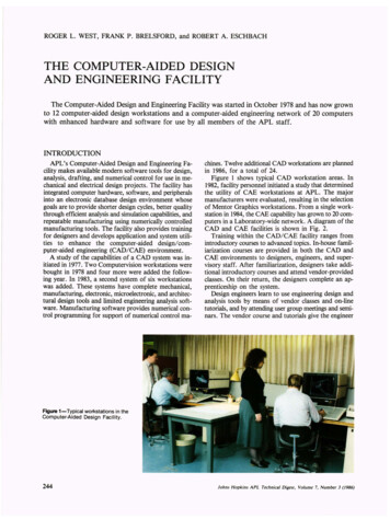
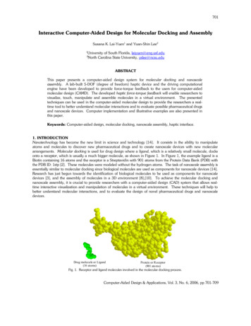
Department of Civil EngineeringAUSTChapter 1Computer Aided Drafting (CAD)The use of computer technology for the process of design documentation (i.e.drafting).CAD may be used to draft in 2D or 3D space.2D User Interface (AutoCAD 2007)Drop Down MenuStandard Tool BarDraw Tool BarStyle Tool BarProperties Tool BarLayer Tool BarModify Tool BarCursorAxisCommand BarCoordinatesStatus BarFigure 1.1: 2D User InterfaceCE 102: Computer Aided DraftingPage 1
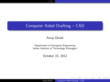
Department of Civil EngineeringAUSTChapter 2Drawing, Editing and DimensioningDrop-Down Menu: All options of AutoCAD can be accessedfrom this menu.Standard Tool Bar: Shows copy, cut, paste, save, zoom icons.Style Tool Bar: Shows current text style, dimension style, tablestyle.Layer Tool Bar: Shows current layer name.Properties Tool Bar: Shows color, line type, line weight.Draw Tool Bar: Shows line, rectangle, circle icons.Modify Tool Bar: Shows modification icons.Command Line: Shows activated command.Frequently Asked QuestionsHow to bring a toolbar on user interface?Right click on any toolbar (i.e. Draw)Select required toolbar (i.e. Dimension) from list (Shownin the figure)Set the position of the toolbar (click at the double lineborder and drag it)How to Change workspace from 3D to 2D or vice versa?Press “Tools”Select “Workplaces”Select “ 3D modeling” or “AutoCAD classic”Figure 2.1: List of all tool barHow to start and terminate commands in AutoCAD?CE 102: Computer Aided DraftingPage 2
Department of Civil EngineeringAUSTThree ways to start a command (i.e. Line)1. From Drop Down Menu ( Draw Line)2. From Command line with short key (Type “ l ” in the command line and press“Enter”)3. From Toolbar (Click on the line command icon on the draw toll bar)Press “Esc” button on keyboard to terminate any command.How to start and complete a drawing?Set drawing unit (Format Unit)Create text styles (Format Text Style)Create dimension style (Format Dimension Style)Create new layers (Format Layer)Draw and modify objects (Use Draw and Modify toolbar or menu)Provide dimensions ( Use dimension toolbar or menu)Write texts (Use draw toolbar or menu)How to save a file?Click “File” on Drop Down Menu barClick “Save as”Select “Drive” to saveRename file name only (keep .dwg as extension)Press “Save”OrPress “Ctrl” SSelect “Drive” to saveRename file name only (keep .dwg as extension)Press “Save”How to plot a file?Press “Ctrl” PSelect printer name / DWG to PDF.pc3 (Use “Printer name” to print and DWG toPDF to publish as pdf)Select paper sizeCheck “Fit to paper”Check “Center the Plot”Press more option (if necessary) Select Plot style table (None is ok. Select Monocrome.ctb for black and whiteprint) Select quality Select drawing orientationPress “Preview”Press “Plot”Why one may use polyline?CE 102: Computer Aided DraftingPage 3
Department of Civil EngineeringAUSTPolylines have some unique qualities that make them very useful:Polylines drawn under one single command can be selected by single click.They can have width (constant or varying)They can consist of arcs and linesThey can be editedThey can be joined together.They can be exploded into individual segmentsEspecially useful for 3D drawingHow to cancel the last command?Press “undo” button on standard toolbarOrPress “Ctrl” “Z”The X-Y Co-Ordinate SystemThe UCS IconFigure 2.2: X-Y Co-ordinateIn the bottom left corner of the AutoCAD drawing window you will see a symbol like oneshown in top. This is called the UCS (User Co-ordinate System) icon and it is there to remindyou which is the X axis and which is the Y axis. In AutoCAD, there are two co-ordinatesystems:World Co-ordinate System: A fixed system.User Co-ordinate System: A movable system.You can relocate the user co-ordinate system using any of these methods:Move the UCS by defining a new origin.Align the UCS with an existing object or with the current viewing direction.Rotate the current UCS around any of its axes.Restore a saved UCS.Using Co-ordinateCE 102: Computer Aided DraftingPage 4
Department of Civil EngineeringAUST ve quadrant(0,0)-ve quadrantFigure 2.3: Co-ordinate SystemCo-ordinates fall into two types, namely Cartesian and Polar. In addition, these two coordinates types come in two distinct flavors. They can be absolute and relative.Cartesian Co-ordinatesDespite the fancy title, the Cartesian co-ordinate system is the standard co-ordinate system.The position of a point can be described by the distance from the axes, X and Y. This resultsin a simple point description using two numbers separated by a comma e.g. 34.897, 45.473.Y Axis34.897,45.473X AxisFigure 2.4: Cartesian Co-ordinate SystemPolar Co-ordinate SystemPolar co-ordinates achieve the same result i.e. the description of the position of a point. Themain difference is that polar co-ordinates use one distance and one angle to describe theposition of a point rather than the two distances in the Cartesian system. The distance andangle measured relative to an origin. This results in a point description which looks like this34.897 30 where the first figure is the distance and the second is the angle.Y Axis(35.8, 60)X AxisFigure 2.5: Polar Co-Ordinate SystemObject SelectionBefore you start to use your AutoCAD commands, you need to know something aboutselecting objects. All of the modify commands require that you make one or more objectCE 102: Computer Aided DraftingPage 5
Department of Civil EngineeringAUSTselections. AutoCAD has wide range of tools which are designed to help you select just theobject you need.1. Selecting Object by PickingPerhaps the most obvious way to select an object is simply to pick it. To select an object,place the pick-box over a part of the object and left click the mouse. When the object hasbeen picked, it is highlighted in a dashed line to show that it is part of the current selectionand the command line reports “1 found”.Figure 2.6: The Pickbox2. Window SelectionThe window option is invoked by typing W in response to the “select objects” prompt.Window allows you to define a rectangle using two points in exactly the same way as theRECTANGLE command. Once all objects which lie within the window will be selected.Figure 2.7: The Window selection box is shown as a rectangle with a solid line3. Crossing Window SelectionThe crossing window option is invoked by typing C at the “Select objects” prompt and isvariation of the Window command. The command sequence is exactly the same but objectsare selected which lie within the window and those which cross the window border.CE 102: Computer Aided DraftingPage 6
Department of Civil EngineeringAUSTFigure 2.8: The Crossing Window selection box is shown as a rectangle with a broken line4. Selecting All ObjectThe All option is invoked by typing ALL at the “Select objects” prompt. You can use thisoption to select all the objects in the drawing, no picking is required. Objects on Locked orFrozen layers are not selected but objects on layers which are simply turned off are selected.5. Using Previous SelectionAutoCAD always remembers the last selection set you defined. This is very useful becauseyou may need to make a number of changes using different commands to the same group ofobjects. In order to reselect the last selection, you can use the previous selection. Theprevious option is invoked by typing P at the “Select objects” prompt.6. Selecting the Last ObjectYou can select the last object created by entering L at the “Select objects” prompt.Units and ScalesIntroduction:Among the most important concepts that newcomers to AutoCAD need to get to grips withare those of drawing scale and units. You cannot start crating sensible drawings withAutoCAD until you are familiar with scale, units and commands you use to control them.Units Control:Command line: Type UN (units) and press EnterFormat menu: UnitsFigure 2.9: Drawing Unit SelectionCE 102: Computer Aided DraftingPage 7
Department of Civil EngineeringAUSTToolbar: noneWhen you start the Units command, the first thing you see is the Drawing Units dialogue box.The dialogue box is divided into four main sections:Length: You can see from the dialogue box that there are five different linear unit types foryou to choose from, one of which is “Decimal”, the default. The table shows the effect of thedifferent unit settings on two drawing unit values to give you an idea how various settingsmust be used along with a brief description.Table 1: The effect of different unit settings on two drawing unit values with descriptionUnit typeDecimalScientific1.5 Drawing Units1.50001.5000E 001500 Drawing Units1500.00001.5000E ctural0’- 1 ric or SI unitsDecimal value raisedto a powerFeet and decimalinchesFeet and fractionalinchesWhole numbers andfractionsNotice that when you change the unit type, the co-ordinate display on the status bar changesto show co-ordinates using the current unit type. Units such as “Architectural” and“Engineering” are mainly for AutoCAD users where Feet and inches are still in common use.Angles: Looking at the Drawing Units dialogue box again, you will notice that there are alsofive angular unit types. The default is decimal degrees, but there are other options. The tablebelow shows the effect of the different unit types on two angular unit values.Unit typeDecimal DegreesDeg/Min/Sec12.5 Angular units12.50012d30’0”180 Angular ic unitsDegrees,Minutesand Seconds400grads 360degrees2 Pi radians 360degreesCompass bearingsCE 102: Computer Aided DraftingPage 8
Department of Civil EngineeringAUSTFigure 2.10: Direction ControlAutoCAD also allows you to control the direction in which angular units are measured andthe position of the start angle. AutoCAD starts with the zero angle at the 3 o’clock position(East) with angles increasing in an anti-clockwise direction. This case may be changed forother modes.Drawing Units for Design Center Blocks: Allows you to assign a specific unit to thedrawing so that when blocks are inserted via the AutoCAD Design Centre, they willautomatically be scaled.Sample output: Gives you a preview of the drawing units as they will be displayed using thecurrent settings.Unit PrecisionThe Drawing Units dialogue box can also be used to set the precision of linear and angularunits. By default, AutoCAD sets the linear unit precision to four places of decimal, so appearin the form 0.0000. Angular unit precision is set to whole degrees only.To change theprecision with which linear and angular values are displayed, simply click the down arrowagainst the appropriate drop-down list and select the number of decimal places required. Thedefault setting of four decimal places is usually adequate for linear units. It is, however, oftennecessary to change the precision for angular units. Working in whole degrees does notusually give an adequate level of detail for many drawing functions. However, you do notneed to change the precision of either linear or angular units unless you have a specific reasonfor doing so.Changing the unit precision does not make your drawing more accurate, it just means that theco-ordinate display on the status bar and the results from the various inquiry commands willbe displayed with a higher degree of precision. The accuracy of your drawing will bedetermined by the values you enter for the size of objects when you draw and edit them andby the correct use of the various object snaps and drawing aids.CE 102: Computer Aided DraftingPage 9
Department of Civil EngineeringAUSTZoom (Standard Tool Bar) (z)1. Pan real time: Move display.2. Zoom real time: Increase or decrease displaysize. (Use mouse scroll as alternative)3. Zoom window: Enlarge the part of the drawing4. Zoom previous: Returns to the last Zoom view.N.B.: To bring all drawings on screen use zoom all (Z A ).Status Bar1. ORTHO (Ortho mode)Click on “ORTHO” button on Status bar or Press F8Enforces to draw horizontal or vertical lines only2. OSNAP (Object snap)Click on “OSNAP” button on Status bar or Press F3 Right click on “OSNAP” button on Status bar Press “Setting” Check desired object snap options Press “ok”Helps to snap (grip) different points during draftingCE 102: Computer Aided DraftingPage 10
Department of Civil EngineeringAUSTFigure 2.11: Available snap options.3. DYN (Dynamic Input)Click on “DYN” button on Status bar or Press F12Shows command line with cursor during execution of any command4. LWT (Line weight)Click on “LWT” button on Status barShows line thicknessDraw Toolbar1. Line (l)a. By picking two pointsSpecify first point (click at any point)Specify next point (click at any point)OrCE 102: Computer Aided DraftingPage 11
Department of Civil EngineeringAUSTb. By direct distance entrySpecify first point (click at any point).Input length (type length of the line)Press “Tab” on the keyboardInput angle (type angle with the X axis)Press enter( ) on the keyboardHorizontal or vertical lineSpecify first point (click at any point)Press “ORTHO” in status bar or press F8 on keyboard.Input length (type length of the line) [Keep the cursor appropriately]Press enter( ) on the keyboard2. Rectangle (rec)a. By picking two pointsSpecify first corner point (click at any point)Specify other corner point (click at any point)Orb. By direct distance entrySpecify first corner point (click at any point)Input length along X (type length of the rectangle)Press “Tab” on keyboardInput width along Y (type width of the rectangle)Press enter( ) on the keyboard3. Circle (c)Specify center point (click at any point)Input radius of the circle (type radius of the circle)Press enter( ) on the keyboardOrSpecify center point (click at any point)Type dPress enter( ) on the keyboardInput diameter of the circle (type diameter of the circle)Press enter( ) on the keyboard4. Arc (a)To draw an arc three points on the arc are necessary. The choice of these points dependson the user or availability of defined points. AutoCAD by default draw arc anticlockwise.So select start and end points properly to get the desired arc shape.CE 102: Computer Aided DraftingPage 12
Department of Civil EngineeringAUSTStart pointEnd pointEnd pointStart pointFigure 2.12: Start point and end point of arcTable 2: Table for available options of arc and its stepsAvailable optionsCenter, Start, EndStart, center, endStart, Center, AngleStart, End, RadiusStepsType cPress enter( ) on the keyboardSpecify center point of the arc (Click at the centerpoint of the desired arc)Specify start point of the arc (Click at the start point ofthe desired arc)Specify end point of the arc (Click at the end point ofthe desired arc)Specify start point of the arc (Click at the start point ofthe desired arc)Type cPress enter( ) on the keyboardSpecify center point of the arc (Click at the centerpoint of the desired arc)Specify end point of the arc (Click at the end point ofthe desired arc)Specify start point of the arc (Click at the start point ofthe desired arc)Type cPress enter( ) on the keyboardSpecify center point of the arc (Click at the centerpoint of the desired arc)Input angle (Angle of end point with X axis at center)Specify start point of the arc (Click at the start point ofthe desired arc)Type ePress enter( ) on the keyboardSpecify end point of the arc (Click at the center pointof the desired arc)Type rCE 102: Computer Aided DraftingPage 13
Department of Civil EngineeringAUSTPress enter( ) on the keyboardInput radius. (type radius of the desired arc)Special note: For simplicity use polyline to draw arc.5. Donut (do)Input inside diameter (generally zero (0))Press enter( ) on the keyboardInput outside diameter ( choose a value based on your drawing )Press enter( ) on the keyboardSpecify center of donut (click at points where donuts are necessary)6. Polygon (pol)Input number of sidesSpecify center of polygon (click at point)Select an option Inscribed in circle Circumscribed about circleInput radius of circleInscribed in circleCircumscribed about circleFigure 2.13: Polygon7. Ellipse (el)Specify first point of major axis (click at point)Specify endpoint of major axis (click at point)Input distance from the midpoint of the first axis to the endpoint of the minoraxisCE 102: Computer Aided DraftingPage 14
DistanceDepartment of Civil EngineeringAUSTFirst pointEnd pointMinor axisMajor axisFigure 2.14: Ellipse8. Region (reg)Select objects ( lines intersect at end points are appropriate objects)Press enter( ) on the keyboardChoice of objectsAppropriateNot appropriate9. Hatch (h)CE 102: Computer Aided DraftingPage 15
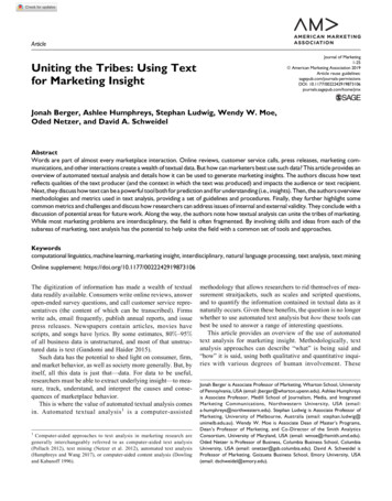
Department of Civil EngineeringAUSTFigure 2.15: Hatch Properties ManagerUse predefined typeChoose the desired pattern ( i.e. concrete, brick etc)Choose angle (Change the orientation of the hatch lines but default isrecommended)Input scale value (Large value lightens the hatch and small value densifieshatch)Choose appropriate boundary selection option Add pick points: Click at any point in a closed boundary (does notwork if any gap on the boundary) Add select objects: Select objects (objects may or may not createclosed boundaryPress enter( ) on the keyboardChoose option Check “ Associative” option to allow modification of hatch shape withthe boundary shape Check “Create separate hatches” option to create separate hatches incase of multiple boundary selectionPress “Preview”Observe hatch createdPress enter( ) on the keyboardIf obtain desired hatch press “ok” or Change parameters and repeat frompreview.AngleAngle and ickGrassGravel10CE 102: Computer Aided DraftingPage 16
Department of Civil EngineeringAUSTFigure 2.16: Hatching optionsChoice of boundary selection“Add pick points”Or “Add select objects”“Add select objects”Figure 2.17: Choosing Area to be HatchedSpecial Notes: One can choose more than one boundary at a time to create hatch (use separateoption for convenience).One can modify any hatch by double clicking.Choose proper island style [if necessary]. Any enclosed area inside the hatchboundary is island.Hatch boundaryIsland style :NormalOuterIgnoreCE 102: Computer Aided DraftingPage 17
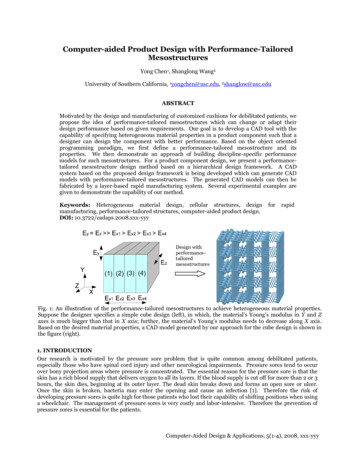
Department of Civil EngineeringAUSTFigure 2.18: Island Style10. Text (t)Draw small windowSelect text style and font (if necessary)Choose text heightWrite on the shaded boxPress enter( ) on the keyboard to go next line (if necessary)Press “ok”Special Notes: One can modify text by double clicking.One can underline a sentence or make a word bold etc.One can insert symbol ( use @ icon)One can insert fraction or subscript or superscript.SuperscriptSubscriptFraction CommandType X2 Select 2 Press “Stack ( )” iconType X 2Select 2Press “Stack ( )” iconType X/YSelect X/YPress “Stack ( )” iconOutputX2X211. BlockFigure 2.19: A dining table as blocka. Insert block (i)Browse (C:\Program Files \AutoCAD 2007 \Sample\Design center\ Housedesigner)Check explodeCE 102: Computer Aided DraftingPage 18
Department of Civil EngineeringAUSTPress “ok”Specify insertion point for block (click at any point of window)Zoom all to see blocksb. Make Block (b)Draw an objectDefine a name to the blockInput base point (Press pick point and click at any point closer to the object)Select object ( select the desired object to make block)Press enter( ) on the keyboardCheck “Convert to Block”Choose appropriate block unitPress “ok”Keep the file for further use as blockModify Toolbar1. Offset (o)Input offset distance (perpendicular distance between parallel lines)Press enter( ) on the keyboardSelect object ( only one line can be selected)Specify point on side to offset ( select any side of the line)2. Copy (co or cp)Select object or objectsPress enter( ) on the keyboardSpecify the base pointSpecify second point or input distance (horizontal or vertical or inclined)3. Move (m)Select object or objectsPress enter( ) on the keyboardSpecify the base pointSpecify second point or input distance (horizontal or vertical or inclined)4. Rotate (ro)AutoCAD by default considers anticlockwise rotation as positive. So to rotate clockwiseone should assign negative angle.Select object or objectsPress enter( ) on the keyboardCE 102: Computer Aided DraftingPage 19
Department of Civil EngineeringAUSTSpecify the base pointInput angle ( angle with X axis)5. Mirror (mi)Select object or objectsPress enter( ) on the keyboardSpecify first point of the mirror lineSpecify second point of the mirror linePress enter( ) on the keyboard6. Extend (ex)Select line or lines as boundary edge ( Right click mouse to select all lines asboundary edges and skip next step)Press enter( ) on the keyboardSelect end of the object or objects closer to boundary edge to extend7. Trim (tr)Select line or lines as cutting edge ( Right click mouse to select all lines ascutting edges and skip next step)Press enter( ) on the keyboardSelect object or objects to trimSpecial Notes: Hold “Shift” key to alter trim and extend command.8. Array (ar)a. Rectangular arrayInput number of row and columnInput row and column offset (Offset means c/c distance of rows or columns )Input angle of array (if necessary) ( indicates the angle of row with positive xaxis)Select objectPress enter( ) on the keyboardPress “Preview”Observe the array createdIf obtain desired array press “accept” otherwise press “Modify” and repeatstepsb. Polar arraySpecify center pointChoose appropriate method of array (i.e. choose any two parameter from totalno. of item, angle to fill and angle between item)Input parameter values Total no. of items: Input number of items to be considered as arrayelementCE 102: Computer Aided DraftingPage 20
Department of Civil EngineeringAUST Angle to fill: Input angle to be filled up by the array elements Angle between items: Input angle between array elements at center ofthe circle.Check/uncheck rotate items as copied (allow/disallow the rotation of arrayelements)Select objectPress enter( ) on the keyboardPress “Preview”Observe the array createdIf obtain desired array press “accept” otherwise press “Modify” and repeatsteps9. Scale (sc)Select object or objectsPress enter( ) on the keyboardSpecify the base pointType scale factor (Greater than 1 to enlarge and less than 1 to shrinkproportionally)Press enter( ) on the keyboard10. Stretch (s)Select object or objects (select only by crossing window)Press enter( ) on the keyboardSpecify the base pointType distance (the distance of the base point movement)Press enter( ) on the keyboard11. Fillet (f)Type r ( to input radius first)P
CE 102: Computer Aided Drafting Page 1 Chapter 1 Computer Aided Drafting (CAD) The use of computer technology for the process of design documentation (i.e. drafting). CAD may be used to draft in 2D or 3D space. 2D User Interface (AutoCAD 2007) Figure 1.1: 2D User