Transcription
Introduction to Computer AidedDesign & AnalysisME 3081
Computer-Aided Design (CAD) Use of computer systems to assist inthe creation, modification, analysis,and optimization of a design Typical tools:– Tolerance analysis– Mass property calculations– Finite-element modeling and visualization Defines the geometry of the design
Computer-Aided Manufacturing (CAM) Use of computer systems to plan,manage, and controlmanufacturing operations Direct or indirect computerinterface with the plant’sproduction resources Numerical control of machinetools Programming of robots
Computer-Aided Engineering (CAE) Use of computer systems toanalyze CAD geometry Allows designer to simulateand study how the product willbehave, allowing foroptimization Finite-element method (FEM)– Divides model intointerconnected elements– Solves continuous field problems
Computer-Aided Design Process Two types of activities: synthesis and analysis Synthesis is largely qualitative and hard tocapture on computer Analysis can be greatly enhanced withcomputers Once analysis is complete, design evaluationrapid prototyping Software packages for design optimization
Components of CAD/CAM/CAE Systems Major component is hardwareand software allowing shapemanipulation Hardware includes graphicdevices and their peripherals forinput and output operations Software includes packages thatmanipulate or analyze shapesaccording to user interaction
7
8
9
10
11
12
13
14
15
16
17
18
19
20
21
22
23
24
25
26
27
28
29
30
31
32
33
34
35
36
37
38
39
40
41
42
43
44
45
46
47
48
49
50
51
52
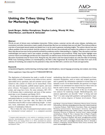
Introduction What is Virtual Reality(VR)?Virtual Reality refers to a high-end userinterface that involves real-timesimulation and interactions throughmultiple sensorial channels.53
Introduction (Cont’d) Why VR?VR is able to immerse you in a computergenerated world of your own making: aroom, a city, the interior of human body.With VR, you can explore any unchartedterritory of the human imagination.54
Brief History In 1950s, flight simulators were built by US AirForce to train student pilots. In 1965, a research program for computergraphics called “The Ultimate Display” was laidout. In 1988, commercial development of VR began. In 1991, first commercial entertainment VRsystem "Virtuality" was released.55
Types of VR System Windows on World(WoW)–Also called Desktop VR.– Using a conventional computer monitor to displaythe 3D virtual world. Immersive VR– Completely immerse the user's personal viewpoint inside thevirtual 3D world.– The user has no visual contact with the physical word.– Often equipped with a Head Mounted Display (HMD).56
Types of VR System(Cont’d) Telepresence– A variation of visualizing complete computergenerated worlds.– Links remote sensors in the real world with the senses of ahuman operator. The remote sensors might be located on arobot. Useful for performing operations in dangerousenvironments.57
Types of VR System(Cont’d) Mixed Reality(Augmented Reality)– The seamless merging of real space and virtual space.– Integrate the computer-generated virtual objects into thephysical world which become in a sense an equal part of ournatural environment.Distributed VR– A simulated world runs on several computers which areconnected over network and the people are able to interact inreal time, sharing the same virtual world.58
VR Examples (Cont’d) Telepresence VR59
Types of VR System(Cont’d) Telepresence– A variation of visualizing complete computergenerated worlds.– Links remote sensors in the real world with the senses of ahuman operator. The remote sensors might be located on arobot. Useful for performing operations in dangerousenvironments.60
Types of VR System(Cont’d) Mixed Reality(Augmented Reality)– The seamless merging of real space and virtual space.– Integrate the computer-generated virtual objects into thephysical world which become in a sense an equal part of ournatural environment.Distributed VR– A simulated world runs on several computers which areconnected over network and the people are able to interact inreal time, sharing the same virtual world.61
VR Examples (Cont’d) Telepresence VR62
VR Examples (Cont’d) Augmented VR63
VR Examples (Cont’d) Distributed VR64
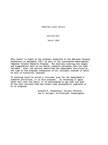
Technologies of VR--Hardware Head-Mounted Display (HMD) A Helmet or a face mask providing the visual and auditorydisplays. Use LCD or CRT to display stereo images. May include built-in head-tracker and stereo headphones65
Technologies of VR--Hardware Binocular Omni-Orientation Monitor (BOOM) Head-coupled stereoscopic display device. Uses CRT to provide high-resolution display. Convenient to use. Fast and accurate built-in tracking.66
Technologies of VR--Hardware Cave Automatic Virtual Environment (CAVE) Provides the illusion of immersion by projecting stereoimages on the walls and floor of a room-sized cube. A head tracking system continuously adjust the stereoprojection to the current position of the leading viewer.67
Technologies of VR--Hardware Data Glove– Outfitted with sensors on the fingers as well as an overallposition/orientation tracking equipment.– Enables natural interaction with virtual objects by hand gesturerecognition.68
Technologies of VR--Hardware Control Devices– Control virtual objects in 3 dimensions.69
Technologies of VR--Software Toolkits– Programming libraries.– Provide function libraries (C & C ). Authoring systems– Complete programs with graphical interfaces for creatingworlds without resorting to detailed programming.70
Technologies of VR--Software Software packages available in market– Multiverse (Freeware)– Virtual Reality Studio ( 100)– Sense8 World Tool Kit (WTK) (over 1000)– Autodesk Cyberspace Development kit (over 1000)71
Technologies of VR--Software VRML(Virtual Reality Modeling Language) –Standard language for interactive simulationwithin the World Wide Web.Allows to create "virtual worlds" networked viathe Internet and hyperlinked with the WorldWide Web.Aspects of virtual world display, interaction andinternetworking can be specified using VRMLwithout being dependent on special gear likeHMD.VR models can be viewed by Netscape or IE with abrowser plug-in.72
Architecture of VR System Input Processor, Simulation Processor,Rendering Processor and World Database.visual,auditory,haptic,touch Position tionProcessorWorld Database73
Components of VR System (Cont’d) Input Processor– Control the devices used to input informationto the computer. The object is to get thecoordinate data to the rest of the system withminimal lag time.– Keyboard, mouse, 3D position trackers, avoice recognition system, etc.74
Components of VR System (Cont’d) World Database (World DescriptionFiles)– Store the objects that inhabit the world,scripts that describe actions of thoseobjects.75
Components of VR System (Cont’d) Rendering Processor– Create the sensations that are output tothe user.– Separate rendering processes are used forvisual, auditory, haptic and other sensorysystems. Each renderer take a descriptionof the world stat from the simulationprocess or derive it directly from the WorldDatabase for each time step.76
Components of VR System (Cont’d) Simulation Processor– Core of a VR system.– Takes the user inputs along with any tasksprogrammed into the world and determinethe actions that will take place in the virtualworld.77
Applications Entertainment– More vivid– Move exciting– More attractive78
Applications (Cont’d) Medicine Practice performing surgery.Perform surgery on a remote patient.Teach new skills in a safe, controlled environment.79
Applications (Cont’d) Manufacturing– Easy to modify– Low cost– High efficient80
Applications (Cont’d) Education & Training––––Driving simulators.Flight simulators.Ship simulators.Tank simulators.81
Current problems & Future work Cybersickness / simulator sicknessLow-fidelityExpensiveLack of integration between application packagesHigh-fidelity systemCost-savingCollaborativeHigh-level contact between participants in distributedVR82
Summary Visualization of complicated, large data is helpfulfor understanding and analysis. VR offers us a new way to interact withcomputer. VR enables us to experience the virtual worldthat is impossible in real world. VR is changing our life, eventually VR willincreasingly become a part of our life.83
84
85
86
87
88
89
90
Components of CAD/CAM/CAE Systems
Hardware Components Graphic device is composed of a displayprocessing unit, a display device, and one or moreinput devices Input devices:––––MouseSpace ballData tablet with a puck or stylusKeyboard Output Devices:– Plotters– Color laser printers
Software Components CAD software allows the designer to createand manipulate a shape interactively andstore it CAM software plans, manages and controlsthe operations of a manufacturing site CAE software analyzes design geometry,allowing designer to study product behavior
Windows-Based CAD Systems User interface is similar to Windows Employs component technology, in which bestkey software elements are selected fromamong available software Use object-oriented technology, whichmodularizes the program Capable of either parametric or variationalmodeling Internet support
CAD/CAM CAD/CAM Computer Aided Design andComputer Aided Manufacturing. It is thetechnology concerned with the use ofcomputers to perform design andmanufacturing functions.95
CAD can be defined as the use of computersystems to perform certain functions in thedesign process. CAM is the use of computer systems toplan, manage and control the operations ofmanufacturing plant through either director indirect computer interface with theplant’s production resources.96
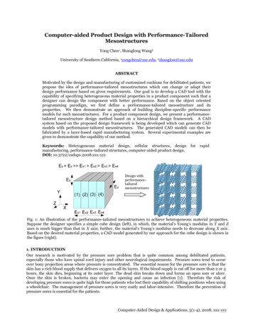
Rapid PrototypingRapid Prototypinghas surgicalapplications Layer by layer fabrication ofthree-dimensional physicalmodels from CAD Fast and inexpensive alternativefor producing prototypes andfunctional models Build parts in thin layers Minimum operation time;typically runs unattended
Medical Modeling - Zcorp
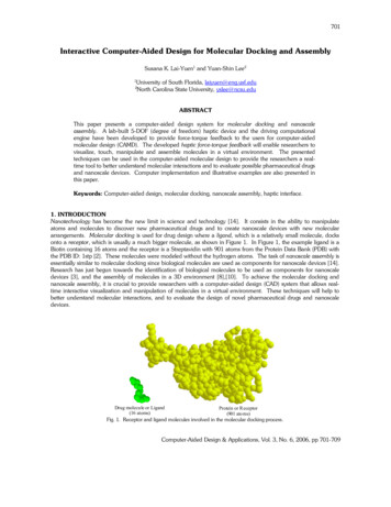
Rapid Prototyping Cycle
Rapid Prototyping Cycle .STL is standard file formatfor all U.S. rapid prototypingsystems Preprocessing prepares .STLfile for various rapidprototyping systems Build process can last from afew hours to several days Post processing: removal ofpart from machine, supportremoval, sanding
Rapid Prototyping Process (Damvig)“A computer-controlled laser beam is scanned across the surfaceof a vat of liquid photopolymer, instantly solidifying the liquid ateach point of contact. Using data generated from a CAD file,individual cross-sections of the three-dimensional geometry aresolidified in turn to build up a solid part layer by layer. In thisway even highly complex geometries can be built in a few hourswithout requiring any tools. “
From CAM definition, the application ofCAM falls into two broad categories:1. Computer monitoring and control .ComputerProcessdataProcess102
2. Manufacturing support application .Process dataMfgComputerControl signals operations103
The Product Cycle and CAD/CAMIn order to establish the scope and definitionof CAD/CAM in an engineering environmentand identify existing and future related tools,a study of a typical product cycle is necessary.The following Figure shows a flowchart ofsuch a cycle.104
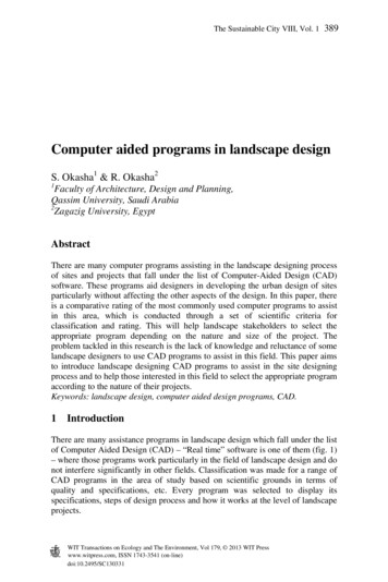
Typical Product Life CycleThe Design ,and requirementsAnalysisDesigndocumentation andcommunicationCollectingrelevant designinformation andfeasibility studySynthesisThe CAD lysisDesignmodeling andsimulationDesignconceptualizationThe Manufacturing ProcessProductionplanningProcessplanningDesign andprocurement ofnew toolsThe CAM dermaterialsNC, CNC, DNCprogrammingMarketing105
The product begins with a need which is identifiedbased on customers' and markets' demands. The product goes through two main processes fromthe idea conceptualization to the finished product:1. The design process.2. The manufacturing process.The main sub-processes that constitute the designprocess are:1. Synthesis.2. Analysis.106
Implementation of a Typical CAD Process on aCAD/CAM systemDelineation of Design changesDesign andgeometric modelAnalysis algorithmsDefinitiontranslatorGeometric modelInterfacealgorithmsDrafting anddetailingDocumentationTo CAM Process107
CAD Tools Required to Support the Design ProcessDesign phaseRequired CAD toolsDesign conceptualizationGeometric modeling techniques;Graphics aids; manipulations; andvisualizationDesign modeling and simulationSame as above; animation; assemblies;special modeling packages.Design analysisAnalysis packages; customizedprograms and packages.Design optimizationCustomized applications; structuraloptimization.Design evaluationDimensioning; tolerances; BOM; NC.Design communication anddocumentationDrafting and detailing 108
Implementation of a Typical CAM Process on aCAD/CAM systemGeometric modelInspectionInterfacealgorithmsAssemblyProcess planningPackagingNC programsTo shipping and marketing109
CAM Tools Required to Support the Design ProcessManufacturing phaseRequired CAM toolsProcess planningCAPP techniques; costanalysis; material andtooling specification.NC programmingPart programmingInspectionAssemblyCAQ; and InspectionsoftwareRobotics simulation andprogramming110
Automation and CAD/CAMAutomation can be defined as thetechnology concerned with the applicationof complex mechanical, electronic, andcomputer-based systems in the operationand control of manufacturing systems.111
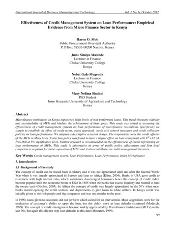
TTypes of Manufacturing Systems1. Continuous-flow processes. Continuous dedicated production oflarge amount of bulk product. Continuous manufacturing isrepresented by chemicals, plastics, petroleum, and food industries.2. Mass production of discrete products. Dedicated production oflarge quantities of one product (with perhaps limited modelvariations). Examples include automobiles, appliances and engineblocks.3. Batch production. Production of medium lot sizes of the sameproduct. The lot may be produced once or repeated periodically.Examples: books, clothing and certain industrial machinery.4. Job-shop production. Production of low quantities, often one of akind, of specialized products. The products are often customizedand technologically complex. Examples: prototypes, aircraft,machine tools and other equipment.112
uctionBatchproductionJob shopproductionProduct variety113
CategoryAutomation achievementsContinuous-flow process Flow process from beginning to end Sensors technology available to measureimportant process variables Use of sophisticated control and optimizationstrategies Fully computer automated linesMass production of discrete products Automated transfer machines Dial indexing machines Partially and fully automated assembly lines Industrial robots for spot welding, part handling,machine loading, spray painting, etc. Automated material handling systems Computer production monitoringBatch production Numerical control (NC), direct numericalcontrol (DNC), computer numerical control(CNC). Adaptive control machining Robots for arc welding, parts handling, etc. CIM systems.Job shop production Numerical control, computer numerical control114
Computer Technology in AutomationMost of the automated production systems implemented todaymake use of computers. CAD/CAM in addition to its particularemphasis on the use of computer technology, is alsodistinguished by the fact that it includes not only themanufacturing operations but also the design and planningfunctions that precede manufacturing.To emphasize the differences in scope between automation andCAD/CAM, consider the following mathematical model:115
Advantages of CAD/CAM systems Greater flexibility.Reduced lead times.Reduced inventories.Increased Productivity.Improved customerservice. Improved quality. Improved communicationswith suppliers. Better product design. Greater manufacturingcontrol. Supported integration. Reduced costs. Increased utilization. Reduction of machinetools. Less floor space.116
Computer-Aided Design (CAD) Use of computer systems to assist in the creation, modification, analysis, and optimization of a design Typical tools: –Tolerance analysis –Mass property calculations