Transcription
ANSYS Workbench – a short guidelineThis document is a guidline on how to use ANSYS Workbench 2.0 as a tool to solve thesecond computer workshop in the course SE1025 FEM for engineering applications. Youare supposed to have read the problem descriptions before proceeding with thisdocument.ANSYS Workbench is a common platform for solving engineering problems. Typicaltasks you can perform in Workbench are: Importing modelsfrom a variety of CAD systems. Conditioning models Performing FEAfor design simulations using the DesignModeler.simulations using Simulation. Optimizing designsusing DesignXplorer or DesignXplorer VT.The underlined words above are the names of different processors within ANSYSWorkbench. Basically, you will use the DesignModeler to create the geometry and theSimulation to set up the materials, FE-mesh, loads and boundary conditions, solve theproblem and analyse the results. The standard interface ANSYS Classic (used in the firstcomputer workshop) is still the core of ANSYS. ANSYS Workbench is a new moderninterface with more up to date functions such as, for example, the integration of CADgeometries.DesignModelerDesignModeler is designed to be used as a geometry editor of existing CAD models.DesignModeler is a parametric feature-based solid modeler designed so that you canintuitively and quickly begin drawing 2D sketches, modeling 3D parts, or uploading 3DCAD models for engineering analysis preprocessing.SimulationUse the Workbench Simulation module to define your model's environmental loadingconditions, solve the simulation, and review results in various formats depending on thetype of simulation.
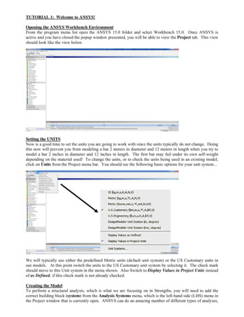
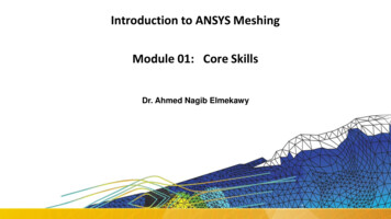
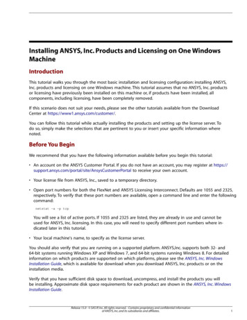
Problem 1NOTE:It is of vital importance that you choose a working directory with enough space available!Otherwise the whole analysis will fail!In this section, the modeling and analysis of the thermo elastic problem will be described.Start the ANSYS Product Launcher. Select a working directory for storing your modeldata and launch ANSYS Workbench. You will see the software outfit as Fig. 1.Figure 1 Software outfit1. Drag Static Structural (ANSYS) tab from Analysis Systems of Toolboxwindow to the Project Schematic window. Now, your static structural analysismodel should be in the Project Schematic, as Fig.2 shows.
Figure 2 Workbench Project Mode2. Double click, then you will go to Engineering Dataatmosphere (as Fig.3). At Properties of Outline Row 3 window, you can fill inthe required material data, and click the data at column E with tab, so that thematerial data you chose will show up in the Parameter Set afterwards. But inStatic Structural mode, you only can define some parameters. The thermalconductivity you have to define it under Steady-State Thermal mode later. Afterfilling parameters, clickto go back the Workbench project mode.
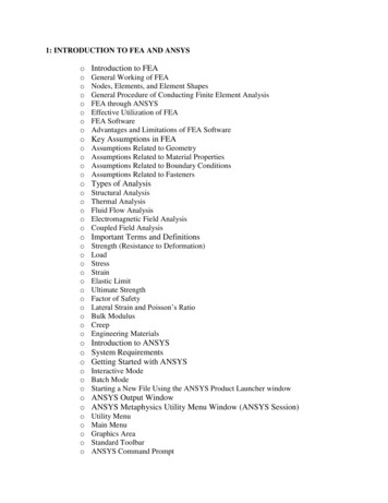
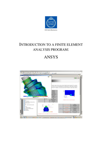
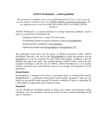
Figure 3 Engineering Data Mode3. When you finish filling the material data, then you can start to build geometry.Double click, and you will activate DesignModeler. A 3D-geometryin DesignModeler is defined on basis of 2D-sketches. The sketches are used toextrude, revolve or sweep a 3D shape. In Fig.4 some basics are described. We willfirst sketch the base of the pipe and fin. The faces will then be used to create thevolume by extrusion.Click the Modeling tab and place the cursor on XYPlane in the modeltree. Create a new sketch by clicking.Click the Sketching tab. Under the Drawing tab, select Rectangle anddraw a rectangle in the drawing window.On the Dimensions tab, select General and dimension the two sides of therectangle: the height and the width. Clicking a side of the rectangle willallow you to define the length of this side. In the”Details View” window,change the dimensions to 100 mm.Create another sketch on the XYPlane. Select Arc by Center and draw aquarter of a circle located inside the triangle, the center point of the arcshould be placed on the bottom left corner of the rectangle. Repeat thisonce so that you obtain two arcs with different diameters. Use thendimension to set the radii to 25 and 20 mm respectively. Connect the endpoints of the arcs with two short lines of 5 mm each.
Create the third sketch on the same plane. This sketch should consist ofone single circle coincident with the two arcs above. The radius should be25mm.Figure 4: Sketching and Modeling modes. On the left, the sketching tab is shown. Here you can usedifferent 2D drawing functions such as line, rectangle and circle for drawing a 2D sketch. On theright, the modeling tab is shown. Here you can find the model tree. In this example there are 3sketches, 3 extrusions and one solid body. Each extrusion is based upon a sketch and each sketch layson a plane, in this case the XYplane.
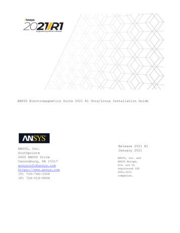
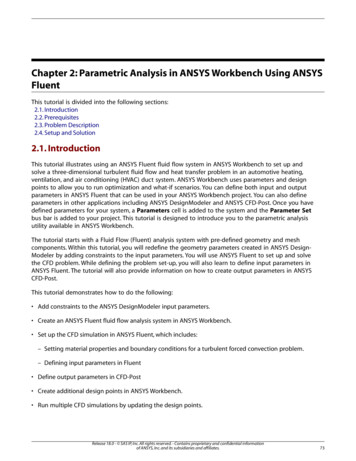
When you are done with the sketches, the result should be something like Fig.5.Figure 5: The three sketches with dimensionsYou will now use the sketches to create extrusions. First you will createthe base plate for the fin. Select the first sketch and click the ExtrudebuttonIn the details window below the modeling tree, check that the Operationis Add Material and that the Depth is 5 mm. To create the extrusion,clickTo create the hole for the pipe, create an extrusion based on the thirdsketch. In the details window, check that the Operation is Cut Materialand that the Type is Through All. To create the extrusion, clickThe pipe is based on the second sketch. In the details window, check thatthe Operation is Add Material, the Depth is 50 mm and that MergeTopology is turned on. To create the extrusion, click
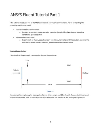
The geometric model is shown in Figure 6.Figure 6: Geometry model.4. Leave DesignModeler, go back to Workbench project mode. The geometry willnow automatically be imported into the simulation processor within Workbench.But don’t forget save everything and then do further simulations.5. And then the following analyze will be done in two steps. The first step is tocalculate that result in mechanics analyses, the second step is to add thetemperature distribution of this cooling flange with results from mechanicalanalyze. We start with the mechanical problem. To start analyze, you need todouble clickat Workbench Project mode. Then you will go tosimulation mode as Fig. 7.Figure 7
6. Following instruction describes how to execute the mechanical analysis:Mesh your model by right click, and choose Generate MeshAdd boundary conditions. Select all symmetry surfaces. Right click onStatic Structural. Under insert select Frictionless Support. To apply theloads, select the inside of the pipe. Right click on Static Structural.Under insert select Pressure. Enter the value of the internal pressure.To solve the problem click the solve button. To see Von-Mises effectstress, right click Solution. Choose Insert Stress Equivalent (VonMises).write down the result.Save your simulation.7. Thermal-Mechanical Analysis:Go back to Workbench project window, and right clickand chooseTransfer Data from New Steady-State Thermal (ANSYS). Then aSteady-State Thermal project has been built which also related to the samegeometry and model of Static Structural project. See Fig. 8Double clickunder Steady-State Thermal project,add thermal conductivity parameter and choose it into parameter set byclick. Click return to project button.Double clickunder Steady-State Thermal projectNow, you can add thermal condition to the simulation. Highlight SteadyState Thermal in Project Tree. Define convection by selectingConvection under insert.Solve this problem and read results of temperature. Add Temperatureinto Solution.Solve the Static Structural problem again with von-Mises effect stressresults. Write down the result. Save your simulation.Figure 8
Problem 2This problem you are supposed to do, more or less, on your own. The pressure vesselfrom the problem description is axisymmetric, so you will only need to model ¼ of the2D cross section of the 3D pressure vessel:1. First of all, mark Geometry under Workbench project mode. And at Propertiesof Schematic A3: Geometry window, expand Advanced Geometry Options.Change Analysis Type to 2D2. Define the material.3. Draw a sketch of the 2D model (¼) in DesignModeler. For 2D FE-models inSimulation, you will need to create a surface from your sketch. When you’re donewith your sketch, on the menu click on Concept – Surfaces From Sketches.NOTE:The option axisymmetry assumes that a 3-D model and its loading can be generated byorevolving a 2-D section 360 about the y-axis. The axis of symmetry must coincide withthe global y-axis. The geometry has to lie on the positive x-axis of the x-y plane. The ydirection is axial, the x direction is radial, and the z direction is in the circumferential(hoop) direction.4. The option for axisymmetry can also be found in the model tree on the left. In the“Details of ”-window for your Geometry, Definition, options for 2D Behaviorare Plane Stress, Plane Strain or Axisymmetry. Choose Axisymmetry. Mesh the2D surface model.5. Define the internal pressure.6. Define the symmetry boundary conditions and add at least one target result.7. Solve and analyze the results.
ANSYS Workbench – a short guideline This document is a guidline on how to use ANSYS Workbench 2.0 as a tool to solve the second computer workshop in the course SE1025 FEM for engineering applications. You are supposed to have read the p