Transcription
Introduction to ANSYS MeshingModule 01: Core SkillsDr. Ahmed Nagib Elmekawy
OverviewIn this lecture we will learn: Meshing Fundamentals ANSYS Meshing interface Geometry concepts Meshing methods Diagnostics & Usability Display Option Mesh Statistics & Mesh Metrics2
Preprocessing WorkflowMeshingGeometryImport /Creation3GeometryCleanup /ModificationsPreprocessingand Solution
Mesh Process & Course PlanGlobalControlsModule 3MeshingMethodsModule 2CoreSkillsModule 1MeshQualityModule 54LocalControlsModule 4
What is ANSYS MeshingANSYS Meshing is a component of ANSYS Workbench Meshing platform Combines and builds on strengths of preprocessing offerings from ANSYS:– ICEM CFD, TGRID (Fluent Meshing), CFX-Mesh, GambitAble to adapt and create Meshes for different Physics and Solvers CFD: Fluent, CFX and POLYFLOW Mechanical: Explicit dynamics, Implicit ElectromagneticIntegrates directly with other WB systems5
Meshing FundamentalsPurpose of the Mesh Equations are solved at cell/nodal locations–Domain is required to be divided intodiscrete cells (meshed)Mesh Requirements Efficiency & Accuracy– Refine (smaller cells) for high solution gradients and fine geometric detail.– Coarse mesh (larger cells) elsewhere. Quality– Solution accuracy & stability deteriorates as mesh cells deviate from idealshape6
Launching ANSYS MeshingANSYS Meshing is launched within Workbench– 2 ways:From Analysis SystemsFluid Flow (Fluent), Static Structural, From Component SystemsMeshDouble clickMesh in theSystemor right click andselect Edit10
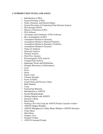
Graphical User InterfaceToolbarsOutlineGraphics windowWorksheetDetails viewManage viewsMessage windowMesh MetricsSection PlanesEntity Details Bar8Units Bar
OutlineThree default sections Geometry– Bodies Coordinate Systems– Default global & user defined systems Mesh– Meshing operations (controls & methods) displayed in the order in which they are insertedIn the tree Right clicking on any object– launches a context sensitive menu– Example: contains commands to generate, preview, clear mesh etc.9
Details ViewAccessing Object Details Select an object (in the Outline)– Related information to that object are displayed in the Details View below– Ex: Select a body (“Fluid”) in the Outline Details of “Fluid” : contains graphical and geometric details– To access meshing details Click the Mesh object or any of the inserted objects The Details View provides options to– review,– edit, or– input10values for every object in the Tree
Geometry Configuration – Multiple Parts Geometry composed of Multiple parts– No connection between parts (no face sharing)‘Contact Region’is automaticallycreated between2 facesGrid interface- FluentEach partmeshedindependentlyResults in Non-conformal interface.Meshes do not match.No nodes connection.Independent faces11GGI - CFXContact Mechanical
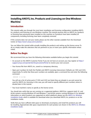
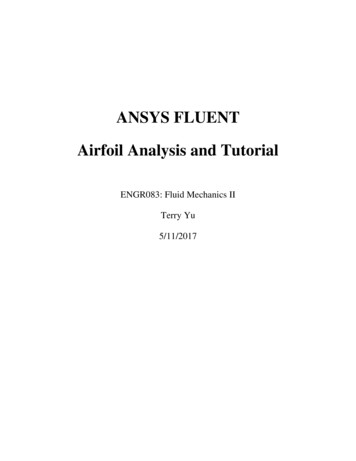
Hexa vs. Tetra Hexa: Concentration in one directionHexa– Angles unchanged Tetra: Concentration in one direction– Angles change Prism: Concentration in one directionTetra– Angles unchangedPrismTetra (in volume)Prisms (near wall)12
Geometry Configuration – Multi-bodyParts Geometry composed of multiple bodies in a part– Depend on ‘Shared Topology method’ (in DM) None– Results in a no connection between the bodies (similar tomultiple parts) AutomaticNote: The CFX users willstill get duplicate nodesat interface in CFX, whichis fine for its solverFaces in contact imprinted & fused toform a single face shared between 2 bodies13Results inConformal meshCommon face actsas ‘Interior’
Geometry Configuration – Multiple – body Parts Geometry composed of multiple bodies in a part ImprintsFaces are imprintedon each other ‘like’ faces14Contact Regionis automaticallycreatedFor identical mesh on thesefaces, use ‘Match Control’Results in unconnected meshnonconformalinterfaceGrid interface- FluentGGI - CFX
Meshing – 3D Geometry (1) 3D cell Types First Meshing ApproachPart/Body MethodsPart/Body based Meshing occurs at part orbody level. Meshing Methods are scopedto individual bodies. Method assignment can beautomatic or manual. Bodies contained in one partare conformally meshed.15 Tetrahedrons. Tetras only Sweep. Prisms & hexahedrons MultiZone. Mainly hexahedron Hex Dominant Not for CFD Automatic. Sweep PC Tet (Dependson bodies) or PC Tet
Meshing – 3D Geometry (2) Second Meshing Approach (mainly for CFD users)Cut Cell MeshingAssembly Meshing Meshes an entire model in oneprocess. Assembly of parts Performs boolean operations. Volume filling, intersection &combination Does not require prior fluid bodydefinition or shared topology. Conformal mesh created acrossparts.16Assembly MeshingMethods Generate mainly Hexahedrons TetrahedronsPart/Body Meshing& Assembly Meshingnot interoperable
Diagnostics: Mesh display By Body Connection (New in R17.0)Default meshdisplayTurningwireframemode onTurning on Mesh display bybodyconnection.19
Named Selections (1)Named Selections are groups of geometric or finite element entities: Named selections can be created either by selecting the desired items and clicking the “NamedSelection” icon in the context toolbar or RMB Named Selection OR using the named selectionworksheet (shown later).RMB Named selections must be composed of “like” entities (all surfaces or all edges, all nodes, etc.).18
Named Selections (2)A new criteria selection can be based on an initial selection: Make an initial selection followed by a RMB “Create Named Selection”. Note, initial selection must be a single entity.Selection here willcreate the first row ofthe worksheet.RMB 19Convert to nodal named selection immediately.
Named Selections (3)In many detail window fields Named Selections can be referenced directly: In the Details view, change “Scoping Method” from “Geometry Selection” to “NamedSelection” Select the “Named Selection” from the pull-down menu A named selection toolbar provides quick access to basic controls “View Toolbars NamedSelections”:20
Usability: Option to save mesh out to separate file (New in R17.0) When “Save Mesh Data inSeparate File” is on the mesh issaved as a separate file (*.acmo). Duplication, Resume, Replace, andSave will handle the separatedatabase and acmo files. Clear generated data will notremove the acmo file. Reset willremove the acmo file. Design Points (also w/RSM)support the separate database andacmo files.This functionality is particularly helpful on Linuxto keep file sizes smaller.21
Usability: Better Meshing Status in R17.0 Progress is reported as parts are meshed in parallel As a part is meshed the topology (edges, faces, bodies) are highlighted to show what isbeing worked on– This can be turned off by unchecking “Highlight”– If user stops meshing, entity will stay highlighted, allowing user to find problematic geometry easierIf user stops meshing, parts that have beenmeshed are done. Restarting meshing resumesonly with unmeshed parts22
Usability: Folders for Meshing Controls in R17.0 Mesh controls can now be grouped for easierorganization Option: Group All Similar Children, will group allobjects based on type Options to suppress, rename, nest groups,ungroup, delete objects in group Drag and drop capabilities to modify the grouping23
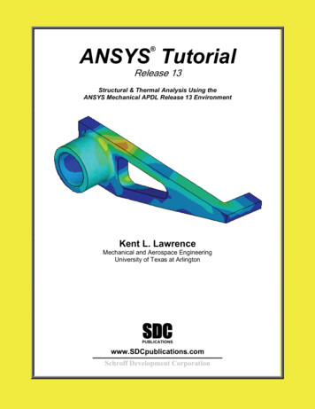
Display Option: Color by qualityProbe ElementValues29Find Min orMax value Displays mesh color by quality metricsOptions to probe quality or show min/maxContour band can be adjustedDisplay meshcontours
Section Planes (1)Displays internal elements of the mesh Elements on either side of plane can be displayed Toggle between cut or whole elements display Elements on the planeEdit Section Plane buttoncan be used to drag section plane to new location Clicking on “Edit Section Plane” button will make section plane’s anchor to appearMultiple section planes are allowedFor large meshes, it is advisable to switch togeometry mode (click on geometry in the TreeOutline), create the section plane and then goback to mesh model39
Section Planes (2) Shaded section planes (New in R17.0)– Shaded or hollow section plane– Plot by body color or same color for section plane26
Mesh Statistics & Mesh Metrics Displays mesh information for Nodes and Elements List of quality criteria for the Mesh Metric– Different physics and different solvers have different requirements for mesh qualityMesh metrics available in Workbench Meshing include:––––––––Element QualityAspect RatioJacobean RationWarping FactorParallel DeviationMaximum Corner AngleSkewnessOrthogonal QualityFor Multi-Body Parts, go to corresponding body in Tree Outlineto get its separate mesh statistics per part/body27
Mesh Metric Graph Displays Mesh Metrics graph for the elementquality distribution Different element types are plotted withdifferent color bars Can be accessed through menu bar usingMetric Graph button Axis range can be adjusted using controlsbutton (details next slide) Click on bars to view corresponding elementsin the graphics window– Use to help locate poor quality elements28
Mesh Metric Graph Controls Elements on Y-Axis can be plotted with twomethods;– Number of Elements– Percentage of Volume/Area Options to change the range on either axis Specify which element types to include in graph––––––Tet4 4 Node Linear TetrahedronHex8 8 Node Linear HexahedronWed6 6 Node Linear Wedge (Prism)Pyr5 5 Node Linear PyramidQuad4 4 Node Linear QuadrilateralTri3 3 Node Linear Triangle Te10, Hex20, Wed15, Pyr13, Quad8 & Tri6 non-linearelementsFor more information about the different mesh metrics please consult module 05: Mesh Quality29
SummaryWhat have we learnt in this session: The global process to run ANSYS Meshing On overview of the interface and The various Geometry configurations– Multiple parts– Multi-body parts– Multiple body partsAnd the associatedshared topology option Meshing methods– Part/body based– Assembly meshing Section Planes Diagnostics & Usability Mesh Statistics & Mesh Metrics Display option30
Workshop 1.1 CFD – ANSYS WB Meshing Basics31
Workshop 1.1 FEA – ANSYS WB Meshing Basics32
Introduction to ANSYS MeshingModule 2:Meshing Methods
Meshing MethodsWhat you will learn from this presentation Meshing Methods for Part/Body Meshing– Assembly Meshing covered separately Methods & Algorithms for;– Tetrahedral Meshing– Hex Meshing– 2D Meshing Meshing Multiple Bodies– Selective Meshing– Recording Meshing Order34
Preprocessing WorkflowGeometry CreationORGeometry ImportSketches andPlanes3D OperationsExtrude, Revolve,Sweep, etcGeometry ImportOptionsDirect CAD/BiDirectional CADGeometryOperations3D OperationsBoolean, BodyOperations, Split,etcMeshingMeshingMethodsHybrid Mesh: Tet,Prisms, PyramidsHexa Dominant,Sweep meshingGeometryCleanup andRepairAssemblyMeshingAutomaticCleanupGlobal MeshSettingsMerge, Connect,Projection, FlowVolumeExtraction, etcLocal MeshSettingsSizing,Body/Sphere ofInfluence, MatchControl, etc35Solver
MethodsWhy Multiple Methods? Choice can depend on;– Physics– Geometry– Resources Mesh could require just one or acombination of methods. Example – Typical mesh designbased on geometric, physics andresource considerations.Hex (3d) or Quad(2d) cells used tomesh simpleregions36High aspect ratio cells(Inflation) near wall tocapture boundary layergradientsCells refined aroundsmall geometricdetails and complexflowTet (3d) or Tri (2d) cells used here to meshcomplex region
Inserting Methods In the Outline, right click Mesh, Insert Method– Select body in Details View Or, in the Graphics Window, Select body(s) , rightclick, Insert Method– Body automatically selected in Details View Method is selectable using the drop down box– Select, Automatic, Tetrahedrons, Hex Dominant,Sweep or Multizone37
Tetrahedrons MethodMethod Behavior Generates tetrahedral elements - two algorithms areavailable: Patch Conforming Patch Independent38
Tetrahedrons Method: Patch ConformingMethod & Algorithm Behavior Bottom up approach: Meshing process starts from edges, faces and then volumeAll faces and their boundaries are respected(conformed to) and meshedGood for high quality (clean) CAD geometries– CAD cleanup required for dirty geometrySizing is defined by global and/or local controlsCompatible with inflationAccess Insert Method and set to Tetrahedrons– Additional drop down box for algorithm choiceappears - Set to Patch Conforming39
Tetrahedrons Method: Patch IndependentMethod & Algorithm Behavior Top down approach: Volume mesh generated first and projected on to faces and edgesFaces, edges and vertices not necessarilyconformed to– Controlled by tolerance and scoping ofNamed Selection, load or other objectGood for gross de-featuring of poor quality(dirty) CAD geometriesMethod Details contain sizing controlsCompatible with inflationAccess Insert Method and set to Tetrahedrons– Additional drop down box for algorithmchoice appears - Set Patch Independent40
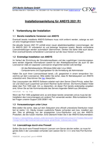
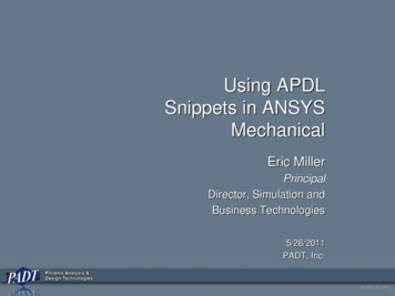
Tetrahedrons Method: AlgorithmComparison (Surface Mesh)Geometry containingsmall detailsPatch Conforming:Allgeometric detail iscapturedPatch Independent: Canignore and defeaturegeometry
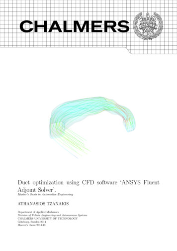
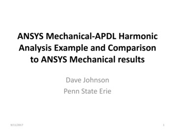
Tetrahedrons Method: AlgorithmComparison (Volume Mesh)Geometry containingsmall detailsPatch Conforming:Delaunay mesh –smooth growth ratePatch Independent: DefaultOctree Mesh – approximategrowth rateSmooth Transition optioncreates Delaunay mesh42
Tetrahedrons Method: ControlPatch Conforming Sizing– Mesh sizing for the Patch Conforming algorithmis defined by Global & Local Controls– Automatic refinement based on curvatureand/or proximity accessible in Global Controls Details of Global & Local Controls covered inseparate lectures– Choice of surface mesher algorithm in globalcontrolsProximityCurvature43
Tetrahedrons Method: ControlPatch Independent Sizing– Sizing for the Patch Independent algorithmdefined in Patch Independent Details
ANSYS Meshing is a component of ANSYS Workbench . Mesh Requirements Efficiency . System or right click and select Edit Launching ANSYS Meshing 10. Mesh Metrics Graphics window Section Planes Manageviews Detailsview Outline Toolbars Entity DetailsBar Units Bar Message window Worksheet Graphical User Interface 8. Three default sections Geometry –Bodies Coordinate Systems .