Transcription
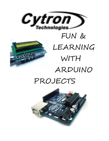
FUN &LEARNINGWITHARDUINOPROJECTS
ROBOT . HEAD to TOEFUN & LEARNING WITH ARDUINO PROJECTSFUN & LEARNING WITHARDUINO PROJECTSBEGINNER GUIDEBYPage 2
ROBOT . HEAD to TOEFUN & LEARNING WITH ARDUINO PROJECTSCONTENTSINTRODUCTION4COMPONENT REQUIRED6OVERVIEW OF ARDUINO DUEMILANOVE 7GETTING STARTED9– ARDUINO IDE9INSTALLATION– INSTALL THE USB DRIVER9– THE ARDUINO IDE SETUP9– THE ARDUINO �PROJECT–––0CONNECTIONADDITIONAL INFORMATIONCODE OVERVIEW1CONNECTIONADDITIONAL INFORMATIONCODE OVERVIEW2CONNECTIONADDITIONAL INFORMATIONCODE OVERVIEW3CONNECTIONADDITIONAL INFORMATIONCODE OVERVIEW4CONNECTIONADDITIONAL INFORMATIONCODE OVERVIEW5CONNECTIONADDITIONAL INFORMATIONCODE OVERVIEW6CONNECTIONADDITIONAL INFORMATIONCODE ITIONAL INFORMATIONCODE OVERVIEW8CONNECTIONADDITIONAL INFORMATIONCODE OVERVIEW9CONNECTIONADDITIONAL INFORMATIONCODE OVERVIEW10CONNECTIONCODE OVERVIEW11CONNECTIONADDITIONAL INFORMATIONCODE OVERVIEW12CONNECTIONCODE OVERVIEW13CONNECTIONADDITIONAL INFORMATIONCODE OVERVIEW14CONNECTIONADDITIONAL INFORMATIONCODE 505151515153535455Page 3
ROBOT . HEAD to TOEFUN & LEARNING WITH ARDUINO PROJECTSINTRODUCTIONsimilar functionality. All of these tools take the messydetails of microcontroller programming and wrap itup in an easy-to-use package. Arduino also simplifiesthe process of working with microcontrollers, but itoffers some advantage for teachers, students, andinterested amateurs over other systems:Arduino is a tool for making computers that can senseand control more of the physical world than yourdesktop computer. It's an open-source ller board, and a developmentenvironment for writing software for the board.Arduino can be used to develop interactive objects,taking inputs from a variety of switches or sensors,and controlling a variety of lights, motors, and otherphysical outputs. Arduino projects can be stand-alone,or they can be communicate with software running onyour computer (e.g. Flash, Processing, MaxMSP.) Theboards can be assembled by hand or purchasedpreassembled; the open-source IDE can bedownloaded for free.The Arduino programming language is animplementation of Wiring, a similar physicalcomputing platform, which is based on the Processingmultimedia programming environment.WHY ARDUINO?There are many other microcontrollers andmicrocontroller platforms available for physicalcomputing. Parallax Basic Stamp, Netmedia's BX-24,Phidgets, MIT's Handyboard, and many others offer Inexpensive - Arduino boards are r platforms. The leastexpensive version of the Arduino module canbe assembled by hand, and even the preassembled Arduino modules cost less than 50. Cross-platform - The Arduino software runson Windows, Macintosh OSX, and Linuxoperating systems. Most microcontrollersystems are limited to Windows. Simple, clear programming environment The Arduino programming environment iseasy-to-use for beginners, yet flexibleenough for advanced users to takeadvantage of as well. For teachers, it'sconveniently based on the Processingprogramming environment, so studentslearning to program in that environment willbe familiar with the look and feel of Arduino. Open source and extensible software- TheArduino software and is published as opensource tools, available for extension byexperienced programmers. The language canbe expanded through C libraries, andpeople wanting to understand the technicaldetails can make the leap from Arduino tothe AVR C programming language on whichit's based. SImilarly, you can add AVR-C codedirectly into your Arduino programs if youPage 4
ROBOT . HEAD to TOEFUN & LEARNING WITH ARDUINO PROJECTSwant to. Open source and extensible hardware - TheArduino is based on Atmel's ATMEGA8 andATMEGA168microcontrollers. The plans forthe modules are published under a CreativeCommons license, so experienced circuitdesigners can make their own version of themodule, extending it and improving it. Evenrelatively inexperienced users can build thebreadboard version of the module in order tounderstand how it works and save money.WHAT YOU WILL NEEDBefore start any project, make sure you get yourselfan Arduino Duemilanove and the necessary Arduinoshield that need to use in the coming project. To getthe Arduino Duemilanove and other extend shieldplease click here.2nd, please download the Arduino software which arerequired to use to write code and upload to the I/Oboard here.Lastly, to get improve of yourself, willingness oflearning is always a matter. Coming project are designin simple and easy understanding to help you to getinvolve in microcontroller easily. It's never too hard tolearn, just spend some time with it and you will like it.Page 5
ROBOT . HEAD to TOEFUN & LEARNING WITH ARDUINO PROJECTSCOMPONENT REQUIREDARDUINO DUEMILANOVEARDUINO PROTOTYPINGSHIELDARDUINO LCD-KEYPADSHIELDARDUINO INPUT SHIELDARDUINO 2-AMP MOTORDRIVER SHIELDARDUINO-XBEE SHIELDRESISTORBREADBOARDLEDSLM35 TEMPRETURE SENSORULTRASONIS RANGE FINDEREZ1PIEZO BUZZERSPG10 MICRO METALGEARMOTORRC SREVO MOTORJUMPER WIRESARDUINO GRAPGIC LCDSHIELDSKXBEEPOTENTIALMETERIR DISTANCE SENSORDC POWER SUPPLYPage 6
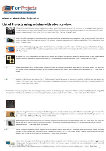
ROBOT . HEAD to TOEFUN & LEARNING WITH ARDUINO PROJECTSOVERVIEW OF ARDUINO DUEMILANOVEAnalog Input Pins6DC Current per I/OPin40 mADC Current for 3.3V50 mAPinThe Arduino Duemilanove ("2009") is amicrocontroller board based on the Atmega168(datasheet) or ATmega328(datasheet). It has 14digital input/output pins (of which 6 can be used asPWM outputs), 6 analog inputs, a 16 MHz crystaloscillator, a USB connection, a power jack, an ICSPheader, and a reset button. It contains everythingneeded to support the microcontroller; simplyconnect it to a computer with a USB cable or powerit with a AC-to-DC adapter or battery to get started."Duemilanove" means 2009 in Italian and is namedafter the year of its release. The Duemilanove is thelatest in a series of USB Arduino boards; for acomparison with previous versions, see the index ofArduino boards.SUMMARYMicrocontrollerATmega168Operating Voltage5VInput Voltage(recommended)7-12VInput Voltage(limits)6-20VDigital I/O Pins14 (of which 6 provide PWMoutput)Flash Memory16 KB (ATmega168) or 32 KB(ATmega328) of which 2 KBused by bootloaderSRAM1 KB (ATmega168) or 2 KB(ATmega328)EEPROM512 bytes (ATmega168) or 1 KB(ATmega328)Clock Speed16 MHzPOWERThe Arduino Duemilanove can be powered via theUSB connection or with an external power supply.The power source is selected automatically.External (non-USB) power can come either from anAC-to-DC adapter (wall-wart) or battery. The adaptercan be connected by plugging a 2.1mm centerpositive plug into the board's power jack. Leads froma battery can be inserted in the Gnd and Vin pinheaders of the POWER connector.The board can operate on an external supply of 6 to20 volts. If supplied with less than 7V, however, the5V pin may supply less than five volts and the boardmay be unstable. If using more than 12V, the voltageregulator may overheat and damage the board. Therecommended range is 7 to 12 volts.The power pins are as follows: VIN. The input voltage to the Arduino boardwhen it's using an external power source (asopposed to 5 volts from the USB connectionor other regulated power source). You canPage 7
ROBOT . HEAD to TOEFUN & LEARNING WITH ARDUINO PROJECTS supply voltage through this pin, or, ifsupplying voltage via the power jack, accessit through this pin. SPI: 10 (SS), 11 (MOSI), 12 (MISO), 13 (SCK).These pins support SPI communication usingthe SPI library.5V. The regulated power supply used topower the microcontroller and othercomponents on the board. This can comeeither from VIN via an on-board regulator, orbe supplied by USB or another regulated 5Vsupply. LED: 13. There is a built-in LED connected todigital pin 13. When the pin is HIGH value,the LED is on, when the pin is LOW, it's off. 3V3. A 3.3 volt supply generated by the onboard FTDI chip. Maximum current draw is50 mA. GND. Ground pins.The Duemilanove has 6 analog inputs, each of whichprovide 10 bits of resolution (i.e. 1024 differentvalues). By default they measure from ground to 5volts, though is it possible to change the upper endof their range using the AREF pin and theanalogReference() function. Additionally, some pinshave specialized functionality: INPUT OUTPUTEach of the 14 digital pins on the Duemilanove canbe used as an input or output, using pinMode(),digitalWrite(), anddigitalRead() functions. Theyoperate at 5 volts. Each pin can provide or receive amaximum of 40 mA and has an internal pull-upresistor (disconnected by default) of 20-50 kOhms. Inaddition, some pins have specialized functions: Serial: 0 (RX) and 1 (TX). Used to receive (RX)and transmit (TX) TTL serial data. These pinsare connected to the corresponding pins ofthe FTDI USB-to-TTL Serial chip. External Interrupts: 2 and 3. These pins canbe configured to trigger an interrupt on a lowvalue, a rising or falling edge, or a change invalue. See the attachInterrupt() function fordetails. PWM: 3, 5, 6, 9, 10, and 11. Provide 8-bitPWM output with the analogWrite()function.I2C: analog input pins A4 (SDA) and A5 (SCL).Support I2C (TWI) communication using theWire library.There are a couple of other pins on the board: AREF. Reference voltage for the analoginputs. Used with analogReference(). Reset. Bring this line LOW to reset themicrocontroller. Typically used to add a resetbutton to shields which block the one on theboard.Page 8
ROBOT . HEAD to TOEFUN & LEARNING WITH ARDUINO PROJECTSGETTING STARTEDFor coming project, we are going to use Arduino IDEto develop and upload the code to the ArduinoDuemilanove. The Arduino IDE are supported toWindow, Mac OS X and also Linux. Be sure to get theone who is suitable to your current using OS. To getthis software, please click here.ARDUINO IDE INSTALLATIONFor Arduino software, installation are no needed. Allwe have to do is download and extract it out andsave it anywhere you like.Next, get yourself anUSB-B type cable thenplug in to the Arduinowhile the other endconnect to the PC.THE ARDUINO IDE SETUPTo start create a project, you may required to doubleclick the arduino.exe which the icon islike the figure beside. This will allowyou to open the Arduino IDE.Next step, you may need to choose the Arduinoboard using for the 1st time such as figure below. Goto Tools Board Arduinio Duemilanove or Nanow/ATmega 328Lastly, you may also choose the COM port forArduino Duemilanove. Same step as above, go toTools Serial Port COM4 (Depend on the PC).INSTALL THE USB DRIVERSTo make your Arduino Duemilanove start talking, youneed to install the USB driver which is located insidethe Arduino IDE you download (drivers/FTDI USBDrivers)Double click this icon and theinstallation will executing. Afterthat, your PC/Laptop will beautomatically detected the driverinstallandyourArduinoDuemilanove are free to use.Page 9
ROBOT . HEAD to TOEFUN & LEARNING WITH ARDUINO PROJECTSTHE ARDUINO IDEWhen you open open up the Arduino IDE, it will looksimilar to the figure above and it may be slightlydifferent to those who are using Mac OS or Linux butthe main function of this IDE are still the same.On the other hand, Arduino IDE also have preparelots of example for user to refer the basic of theoperating code. By clicking File Example, there waslots of sample program to be explore.Above there was a Toolbar which consist of 7 itemwhich is which is start from the left (compile , stop,new, open, save, upload and serial monitor).Page 10
ROBOT . HEAD to TOEFUN & LEARNING WITH ARDUINO eStop the serial monitor, or un-highlights other buttonNewCreates a new blank SketchOpenShow a list of Sketches in your Sketches bookSaveSave the current SketchSerial MonitorSerialmonitorCheck the code for errorStopUploadUploadUpload the current Sketch to ArduinoDisplay serial data being sent from ArduinoVerify/ Compile is use to check the code writingwhether is correct or not before upload to Arduino.to verify/ compile the code before uploading toensure the code have no errors.Stop button are use to stop the operation of theserial monitor and also un-highlighted other selectedbutton. While press stop in serial monitor, it wil stopthe operation of it and user may take a 'snapshot' ofthe serial data they examine.Serial monitor is an very useful too to communicatewith computer while it still can use to debuggingyour code. The monitor will display the data sendingin and out from the computer to the Arduino.New button are use to create a complete new sketchfor user to develop their new program.Open button will present you a list of the sketchesstore in the sketch book as well as a list of examplewhere allow user to try out.Well, don't get too worry about the IDE using as nowyou have already pick up some important step todeal with it. So, let's go to explore some projectscode now!Save button will save the sketch you developed codeto the folder you required. The Arduino IDE willautomatically create an folder and store the code.Upload to I/O board will allow user to load theircode onto the Arduino with the current sketch. Youmay need to make sure the correct board and portusing(Tools menu) before uploading. You areencourge to save before uploadto avoid error whichmake your system hang or IDE to crash. It is advisablePage 11
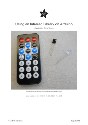
ROBOT . HEAD to TOEFUN & LEARNING WITH ARDUINO PROJECTSPROJECT 0LED DICEDice, which all of us are normally will use it whenplaying a games especially monopoly. But have weever head of LED dice? LED dice, one of theinteresting project using LED except from LEDblinking. In here, we going to experience on how tomake an LED dice with a few LEDs interface withArduino Duemilanove.COMPONENT NEEDEDCONNECTIONFirstly, we arrange the LEDs like the shape of thedice. Then connect the LED1 to LED7 to digital port-2until port-8. Connect a pull-up switch to control theoperation of the LED dice which is connected todigital port 11. Every LEDs are connected with an 1Kresistor to prevent over current LED which will makethe LED spoil.ARDUINO-PROTOTYPINGSHIELDJUMPER WIRELEDs1K RESISTORPage 12
ROBOT . HEAD to TOEFUN & LEARNING WITH ARDUINO PROJECTSADDITIONAL INFORMATIONARDUINO PROTOTYPING SHIELDThis is a design for an open-source prototyping shieldfor Arduino NG/Diecimila. It has tons of coolfeatures, to make prototyping on your Arduino easy.Please refer to Arduino Prototyping Shield schematicfor detail connection.Features: Reset button up top ICSP header Lots of GND and 5V rails DIP prototyping area makes it easy to addmore chips. SOIC prototyping area above USB jack for upto 14-pin SOIC chip, narrow medium or widepackage. A 'mini' breadboard included Extra 6mm button Compatible with: Arduino Duemilanove,Arduino NG, Arduino Diecimila.Page 13
ROBOT . HEAD to TOEFUN & LEARNING WITH ARDUINO PROJECTSLIGHT EMITTING DIODEBREADBOARDFigure above have shows that the connection of halfof the breadboard. The RED and BLACK colour lineare usually been connect to power supply (VDD) andground (GND). They are connected all the way fromthe beginning to the end but they did not connect toeach other.There are few method to determine the anode andcathode side of the LED such as :1. The flat spot on the lens/case of the LEDis cathode.2. The short lead (or leg) is cathode.3. The flag symbol inside the lens iscathode.For further information about LED, please refer tothis webpage.Besides that, the orange colour line are the part thatwe usually use to place the electronic component.They are connected in a straight line.There is a gap in the middle of the breadboard whichare not connected to anything. This allow you to putintegrated circuit across the gap and have each pin ofthe chip go to the different set of holes and thereforea different rial.RESISTOR COLOUR TABLEAbove are the example of resistor with the colourPage 14
ROBOT . HEAD to TOEFUN & LEARNING WITH ARDUINO PROJECTScode example. For more detail, refer to thiswebpage.pinMode (pinLeds1, OUTPUT);Declare the pin as an OUTPUT pin.CODE OVERVIEWpinMode (buttonPin, INPUT);Declare the pin as an INPUT pin.randomSeed (analogRead(0));Initializes the pseudo-random number generator,causing it to start at an arbitrary point in its randomsequence.const int pinLeds1 2;Define Arduino pin 2 as pinLeds1 and so on for totalof 7 LEDs.unsigned char ran 0;Define ran as 0 while defining the maximum storageas a byte.Int buttonState;Define the buttonState as an integer.void loop()The program under void loop will be loop forever.ButtonState digitalRead(buttonPin);Read the input value from buttonPin 11, then storethe result in ButtonState.while (buttonState LOW){ran random(1,7)};Loop forever until the buttonState,LOW(0), isdetected. After that execute the random numberchoosing between 1 to 7.if (ran 1)If ran is 1 then execute the following program.void setup ()In here, we use to declare the pin using whether isInput or output pin.digitalWrite (pinLeds4, HIGH)Digitally write the pinLeds4 to High(1) the digital pin4.Page 15
ROBOT . HEAD to TOEFUN & LEARNING WITH ARDUINO PROJECTSdelay(50);Delay for 50ms.while(digitalRead(buttonPin) HIGH);Check if the button pin is release. If yes, then staythere until is press again.led clear();Call and execute the led clear program.This subroutine are operate to LOW(0) or off all theLED pins by digitally write the pinLeds from 1 to 7 toLOW(0).References:1. http://en.wikipedia.org/wiki/Lightemitting diode2. http://www.elexp.com/t resist.htm3. http://www.cytron.com.my/usr attachment/Arduino-proto.pdfPage 16
ROBOT . HEAD to TOEFUN & LEARNING WITH ARDUINO PROJECTSPROJECT 1“Hello World” ON LCDArduino LCD Keypad Shield or navigation shieldwhich come with 6 momentary push button formenu navigation and also a 2x16 LCD. It onlyrequired to plug and use with Arduino main boardand there no soldering or fly-wiring are required.COMPONENT NEEDEDARDUINO LCD-KEYPADSHIELDArduino LCD 2x16 SchematicCONNECTIONFor the LCD Keypad Shield, it use total of 6-pins tocontrol the LCD display which is pin-4,5,6,7,8,9. ForLCD data, it use pin-4,5,6,7, while for the RS andEnable pin, it use pin-8 and 9. The Arduino-LCDKeypad Shield are only required to plug into theArduino main board and there was no soldering arerequired such as shown in figure below.Page 17
ROBOT . HEAD to TOEFUN & LEARNING WITH ARDUINO PROJECTSArduino Keypad SchematicCODE OVERVIEW#include LiquidCrystal.h Include the LiquidCrystal header file which is alreadyprepared inside the Arduino libraries.LiquidCrystal.lcd(8, 9, 4, 5, 6, 7);In here, we set the pin using for LCD 4-bit mode byrefer to Arduino Liquid Crystal webpage which isLiquidCrystal(rs, enable, d4, d5, d6, d7).ADDITIONAL INFORMATIONThe Arduino-LCD Keypad Shield are operate in 4-bitsmode. To ease user, Arduino Team have prepared the LiquidCrystal.h file which we only require tomodified and change the pin using only. For moreinformation please check the Arduino LCD keypadShield schematic.For more example of the Arduino LCD Keypad coding,please refer to this webpage.Int analogPin A0;Define the A0 as analogPin while assign a space to itas an integer.Int adc key val[5] {30 , 150 , 360, 535, 760};Define the adc key val from 0 to 4 which contain thenumber inside the bracket. E.g: adc key val[1] 150;char msgs [5][15] {“Right Key OK”,Page 18
ROBOT . HEAD to TOEFUN & LEARNING WITH ARDUINO PROJECTS“Up Key OK ”,“Down Key OK”,“Left Key OK ”,“Select Key OK”};Define the each ASCII value in char which content oftotal 5 string and there was 15 ASCII value for eachstring.adc key in analogRead(analogPin);Read the value from the specified pin (analogPin)and store the value in the adc key in.adc key in get key(adc key in);Send the adc key in value tosubroutine.theget keylcd.print(msgs[adc key in]);Print the text on the msgs[] to the LCD displayaccording to the adc key in.lcd.begin(16,2);Specified the dimension (width and height)of theLCD display.lcd.clear();Clear the screen of the LCD display.lcd.print(“ CYTRON TECH.”);Send the ASCII code to the LCD display according tothe text enter.lcd.setCursor(0,1);Position the LCD cursor,that is set the location atwhich subsequent text written to the LCD will bedisplayed.for(k 0; k NUM KEYS; k )Loop from k 0 to k 4.If (input adc key val[k])Check of the value from the analogPin are less thanadc key val[k].return k;Replace the original k value with the number of kPage 19
ROBOT . HEAD to TOEFUN & LEARNING WITH ARDUINO PROJECTSfrom 0 to 4.If (k NUM KEYS)k -1;If detected the k value are large, assign k -1.References:1. http://arduino.cc/en/Tutorial/HomePage2. http://www.cytron.com.my/usr attachment/LCDKeypad%20Shield%20SCH.pdfPage 20
ROBOT . HEAD to TOEFUN & LEARNING WITH ARDUINO PROJECTSPROJECT 2GRAPHIC LCD DISPLAYArduino Duemilanove have come with a Graphic LCDshield which allow allow user to play with more pixelbesides LCD. This shield have 48x84 pixel resolution.If your project need more information to display, thisLCD shield can apparently meet your needs. It is ableto display English, Chinese, even images.COMPONENT NEEDEDARDUINO -GRAPHIC LCDSHIELDCONNECTIONin the coding, the shield are ready to display.ADDITIONAL INFORMATIONFor Arduino- GLD shield, It also integrates a 5 DOFjoystick. The shield has 6 Digital IO and 5 Analog IO.Besides that, we may control the backlight by justuse digitalWrite(7, HIGH/LOW) to turn it on and off.Don’t forget to put pinMode(7, OUTPUT) in voidsetup();.Well, reading the joystick position is accomplishedvia analogRead(0);. It returns the following values assuch: Up – 505 Down – 0 Left – 740 Right – 330 pressed in – 144 Idle (no action) – 1023CODE OVERVIEWReferring to the Figure above, the GLCD are onlyrequired to plug into Arduino Duemilanove then putint adc key in;Define the adc key in as a storage space of integer.Page 21
ROBOT . HEAD to TOEFUN & LEARNING WITH ARDUINO PROJECTSint joy stick 0;Define the joy stick I/O as analog port 0.Write a string of number in every row.int adc key val[5] {50,200,400,600,800};Initial the joy stick ADC value.#define LCD Backlight 7Define the LCD Backlight pin as ditial pin 7.#define NUM KEYS 5Define the total number of key is 5.lcd.LCD write string big(0,0,”012345”,MENU NORMAL);Write a string of number in big font size.References:1. robot-lcd4884-lcd-shield/2. http://www.dfrobot.com/wiki/index.php?title LCD4884 Shield Fro Arduino (SKU:DFR0092)lcd.LCD init();Graphic LCD Initialize.Lcd.LCD clear();Clear the GLCD screen.pinMode(LCD Backlight, OUTPUT);Make the LCD Backlight pin as output.lcd.LCD draw bmp pixel(2,1,cytron,80,24);Display the picture in Bitmap format in (2nd row, 1stcolumn, cytron logo, picture's width, picture'sheight).lcd.LCD write string(0,a,”01234567890123”,MENUNORMAL);Page 22
ROBOT . HEAD to TOEFUN & LEARNING WITH ARDUINO PROJECTSPROJECT 3LED CHASERDice, which all of us are normally will use it whenplaying a games especially monopoly. But have weever head of LED dice? LED dice, one of theinteresting project using LED except from LEDblinking. In here, we going to experience on how tomake an LED dice with a few LEDs interface withArduino Duemilanove.COMPONENT NEEDEDCONNECTIONReferring to the figure below, there are total 6 LEDswhich is anode are connected to digital port(2,3,4,5,6,7). While other end are connected to 1Kresistor and to ground GND. Next, connect thepotentialmeter which one end RED wire to VDD(5V),the other end BLACK wire connected to ground GNDwhile the middle pin YELLOW wire is connect toanalog input A0.BREADBOARDJUMPER WIRELEDs1K RESISTOR5K POTENTIALMETERPage 23
ROBOT . HEAD to TOEFUN & LEARNING WITH ARDUINO PROJECTSADDITIONAL INFORMATIONCODE OVERVIEWbyte pinLeds[] {2,3,4,5,6,7};Define the pin using in array . Which in this project,the pin using are pin 2,3,4,5,6 and pin 7.Potentiometer BasicsA potentiometer is a type of variable resistor,made so that it can be easily adjusted. A resistoris an electronic component whose function is toresist the flow of electricity. The moreresistance, the slower the electric current flows.Because a potentiometer allows a user to adjustthe resistance, it can be used to adjust a circuitwhile it is running.Potentiometer StructureA potentiometer has three contacts - two fixedcontacts on either end and a movable one calleda wiper. As the wiper moves closer to one fixedcontact, it moves further away from the other,decreasing the resistance with the closer oneand increasing it with the further one. Somepotentiometers, called rheostats only have twocontacts - a fixed one and a wiper. In both cases,the position of the wiper is usually adjusted byturning a knob or moving a slider.for (x 0 ; x 6 ; x ){pinMode (pinLeds[x],OUTPUT)}Loop from x 0 until x 5 and assign the pin to output.E.g: When x 3. pinMode(pinLeds[3],OUTPUT);delay period analogRead(analogPin);Read the ADC value from analogPin,A0, by assigningthe code analogRead. After that store the value indelay period. The ADC for Arduino microcontroller(ATMEGA398P) containing 10 bits of ADC so theoutput value may between 0 to 1022 which will betaken as an delay value.Page 24
ROBOT . HEAD to TOEFUN & LEARNING WITH ARDUINO PROJECTSCurrentLED direction;Decide the LED direction by assigning the value by 1or -1.if (currentLED 5) {direction -1;}if (currentLED 0) {direction 1;}Check the LED location and decide whether is 5 or 0.If is 5, then assign -1. If is 0, then add 1.References:1. http://en.wikipedia.org/wiki/Potentiometer2. Page 25
ROBOT . HEAD to TOEFUN & LEARNING WITH ARDUINO PROJECTSPROJECT 4KNIGHT RIDER LIGHT BAREver watch knight rider movie? The car (KITT) have avery cool light bar in front and where most peoplelike to have one of it. Here, we are going to make oneof it using Arduino Duemilanove interfacing with 8LEDs. Enjoy.(GND).COMPONENT NEEDEDBREADBOARDJUMPER WIRELEDsADDITIONAL INFORMATION1K RESISTORCONNECTIONThere are total of 8 LEDs using which he anode areall connected to digital port (2,3,4,5,6,7,8,9) whichORANGE wires. On other hand, the cathode of LEDsare connected to 1K resistor then go to groundFor this project, user are require to download a newlibrary file for Arduino here. This is a SoftPWM librarywhich use to generate simple PWM using timer 2.To insert the file into Arduino library, please followthe following steps.1. After download, extract the file and save it atyour arduino-0022\libraries.Page 26
ROBOT . HEAD to TOEFUN & LEARNING WITH ARDUINO PROJECTS2. Restart your arduino.exe (if you are currentlyusing it). Range: 0 to 4000CODE OVERVIEW#include SoftPWM.h Include the header file always at the beginning of theeach program.Int leds[8] {2,3,4,5,6,7,8,9};Define the LEDs pin using on each digital port.SoftPWMSet (leds[i 1], 255);Set the desire pin to HIGH(1) and LOW(0)E.g: if i 0, (leds[ i 1] 1, 255) (pin-3, ON)(leds [6 – i] 6, 255) (pin-6, ON)(leds [i] , 0) (pin-0 , OFF)(leds [7-i], 0) (pin-7, OFF)References:1. http://www.arduino.cc/cgibin/yabb2/YaBB.pl?num 1276737123SoftPWMBegin();Initializes the library - sets up the timer and othertasks.2. raryDocumentation#DescriptionSoftPWMSet (leds[i], 0);SoftPWMSet(pin, value) pin is the output pin. Value is a value between 0 and 255 (inclusive).SoftPWMSetFadeTime (ALL, 30, e) pin is the output pin. Fadeuptime is the time in milliseconds that it willtake the channel to fade from 0 to 255. Range: 0 to 4000 fadedowntime is the time in milliseconds that itwill take the channel to fade from 255 to 0.Page 27
ROBOT . HEAD to TOEFUN & LEARNING WITH ARDUINO PROJECTSPROJECT 5RC SERVO MOTOR POSITIONNowadays, most hobbyist like to use RC servo motorto control their robot or others than that which needa precise position while a cheapest price. For thisproject, we are going to discover how to control 2 RCservo motor together using Arduino Duemilanovewith Arduino Input Shield.COMPONENT NEEDEDBREADBOARDRC SERVO MOTORCONNECTIONServo motors have three wires: power, ground, andsignal. The power wire is typically RED, and should beconnected to the 5V pin on the Arduino board. Theground wire is typically BLACK or BROWN and shouldbe connected to a GND pin on the Arduino board.The signal pin is typically YELLOW, ORANGE or WHITEand should be connected to a digital pin 6 on theArduino board.Note servos draw considerable power, so if you needto drive more than one or two, you'll probably needto power them from a separate supply (i.e. not the 5V pin on your Arduino). Be sure to connect thegrounds of the Arduino and external power supplytogether.ARDUINO INPUT SHIELDJUMPER WIREPage 28
ROBOT . HEAD to TOEFUN & LEARNING WITH ARDUINO PROJECTSADDITIONAL INFORMATIONCODE OVERVIEWARDUINO RC SERVO LIBRARYThis library allows an Arduino board to control RC(hobby) servo motors. Servos have integrated gearsand a shaft that can precisely controlled. Standardservos allow the shaft to be positioned at variousangles, usually between 0 and 180 degrees.Continuous rotation servos allow the rotation of theshaft to be set to various speeds. The Servo librarysupports up to 12 motors on most Arduino boards.WIRE CONNECTIONServo servo1;Define the servo name as servo1.Above are the picture showing that the differentcolour of wire using in different brand of servomotor. For more information, please refer to thisservo wiring information.HOW RC SERVO WORKTo control the RC servo position, we have to send a20ms plus to the RC servo with a 0.5ms to 2.5m
– THE ARDUINO IDE PROJECT 0 . we have to do is download and extract it out and save it anywhere you like. Next, get yourself an USB-B type cable then plug in to the Arduino while the other end connect to the PC. INSTALL THE USB DR