Transcription
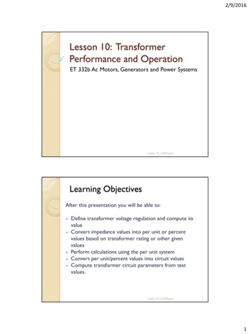
2/9/2016Lesson 10: TransformerPerformance and OperationET 332b Ac Motors, Generators and Power SystemsLesson 10 et332b.pptx1Learning ObjectivesAfter this presentation you will be able to: Define transformer voltage regulation and compute itsvalueConvert impedance values into per unit or percentvalues based on transformer rating or other givenvaluesPerform calculations using the per unit systemConvert per unit/percent values into circuit valuesCompute transformer circuit parameters from testvalues.Lesson 10 et332b.pptx21
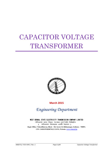
2/9/2016Transformer Voltage RegulationDefinition: Difference between output voltage at no load andoutput voltage at rated load divided by rated voltage V VR%VR NLVR 100% Where VR rated output voltageVNL full load output voltageNote: allvoltages aremagnitude onlyAlso given in "Per Unit" - fraction from 0 - 1.0 V VR VR NL VR Lower values of regulation are better. Indicates that there is less voltage dropacross the transformer.Negative regulation is possible. Indicates voltage rise across transformer. ( dueto leading p.f. load)Lesson 10 et332b.pptx3Voltage Regulation Circuit ModelVoltage regulation found through calculation that uses the total windingimpedanceTo compute %VRE LS I LS ZeqLS VLS E VLS%VR NLVLS 100% Where: VLS rated low side voltage (switch closed)ELS no load low side voltage (switch open)ILS low side load current at specified P.F.ZeqLS total winding impedance referred to L.V. sideLesson 10 et332b.pptx42
2/9/2016Transformer Voltage RegulationExample 10-1: A 500 kVA 7200 - 2400 V single-phasetransformer is operating at rated load with a power factorof 0.82 lagging. The total winding resistance and reactancevalues referred to the high voltage side are Req 0.197 andXeq 0.877 ohms. The load is operating in step-down mode.Sketch the appropriate equivalent circuit and determine:a) equivalent low side impedanceb) the no-load voltage, ELSc) the voltage regulation at 0.82 lagging power factord) the voltage regulation at 0.95 leading power factorLesson 10 et332b.pptx5Example 10-1 Solution (1)a) Refer impedances to low voltage side of transformerAnsAnsb) no-load secondary voltageELS voltage required to supply rated power at rated voltage so.Lesson 10 et332b.pptx63
2/9/2016Example 10-1 Solution (2)Determine the phase angle on the current using the power factorLagging Fp meansnegative angleAnsLesson 10 et332b.pptx7Example 10-1 Solution (3)c) Compute the percent voltage regulation for 0.82 lagging power factorAnsd) Compute the percent voltage regulation for 0.95 leading power factorCompute the no-load voltageLesson 10 et332b.pptx84
2/9/2016Example 10-1 Solution (4)No-load voltage issmaller than VsCompute regulationNegative %VRindicates LCresonance intransformer/loadcombinationLesson 10 et332b.pptx9Per Unit and Percent Impedance ofTransformersEquivalent circuit calculation requires knowledge of turns ratio andreference of impedance values from one side to other. Per Unit systemis normalization scheme that removes the effect of turns ratio frompower system calculations.Transformer manufacturers list impedances for transformers usingPer Unit or Percent impedance methodLesson 10 et332b.pptx105
2/9/2016Per Unit and Percent Impedance ofTransformersPer Unit impedance calculation needs base quantitiesPer Unit MethodDefine base power and voltage. Compute base Z and I from thesequantities. Divide actual impedances. voltages and currents by bases toget per unit valuesFor transformersSbase SratedBase power defined as the rated power of theelectrical deviceVbase VratedBase voltage defined as the rated voltages of thetransformerLesson 10 et332b.pptx11Per Unit Computation MethodComputing Per Unit (percent) basesI base SbaseVbaseZbase VbaseI baseorZbase Vbase 2SbaseResistance, reactance and impedances can now be divided by Zbase toget per unit values based on transformer rated power and voltage.Multiply per unit by 100 to get percent impedance.Zpu ZactZbaseX pu X actZbaseR pu R actZbaseWhere: Zact device impedance in ohmsRact device resistance in ohmsXact device reactance in ohmsLesson 10 et332b.pptx126
2/9/2016Per Unit CalculationsPer Unit (percent) impedances and components alsoadd as vectorsZpu R pu j X puZpu R pu X pu22 X pu tan 1 R pu Other p.u. quantitiesI pu I actI basePpu PactSbaseVpu VactVbaseQ pu Q actSbaseOhm’s law and all other circuit theorems are valid for p.u.impedances, voltages, currents and powerLesson 10 et332b.pptx13Per Unit Values of a TransformerExample 10-2: The equivalent circuit above is for a single phase 25kVA 7200 - 240 volt transformer. The parameters have the followingvalues:Rp 1.40 W Xlp 0.25 W Rs 0.11 W Xls 3.20 WRfe 19,501 W Xm 5011 WConvert these values to per unit values based on the current andvoltage ratings of the primary and secondary of the transformer.Draw the equivalent circuit with the per unit values labeled.Lesson 10 et332b.pptx147
2/9/2016Example 10-2 Solution (1)Select Vbase 7200 V and Sbase 25 kVA for primary sideDivide all actual values located on primary side by ZbaseAnsAnsLesson 10 et332b.pptx15Example 10-2 Solution (2)AnsAnsConvert secondary values to per unitCompute p.u. valuesLesson 10 et332b.pptx168
2/9/2016Example 10-2 Solution (3)Refer the Xls and Rs to primary side and compute p.u. values usingprimary ZbaseSame values as low-voltage side p.u. calculation. Per unit withtransformer voltage ratings as base voltages removes turns ratiofrom all calculationsLesson 10 et332b.pptx17Transformer Ratios and Per UnitWhen common power base is used, and voltage bases are defined astransformer rated voltages, p.u. (percent) values are the same on bothside of transformer. This means that the ideal transformer can beremoved from schematic and calculations done in p.u.To get actual values from p.u.Zact Zbase ZpuVact Vbase VpuIact I base I puPact Sbase PpuQact Sbase QpuSact Sbase SpuNote: Rated voltage and current values are 1.0 p.u.Ohm's Law holds in p.u. so.Vpu I pu ZpuI pu VpuZ puZ pu VpuI puLesson 10 et332b.pptx189
2/9/2016Per Unit CalculationsExample 10-3: A 50 kVA 7200-240 V single phase transformer has anequivalent series impedance of 25 75 Ohms in terms of the highvoltage side. The transformer supplies a 45 kVA load with 0.89 laggingpower factor at rated voltage. Find:a) Per unit Zeq with rated high-side voltage as the base voltageb) Per unit Zeq with rated low-side voltage as the base voltagec) The %VR using per unit valuesLesson 10 et332b.pptx19Example 10-3 Solution (1)a) Primary side values in p.u.b) Secondary side values in p.u.Lesson 10 et332b.pptx2010
2/9/2016Example 10-3 Solution (2)c) Find the %VRLesson 10 et332b.pptx21Example 10-3 Solution (3)Lesson 10 et332b.pptx2211
2/9/2016Example 10-3 Solution (4)Lesson 10 et332b.pptx23Per Unit Circuit AnalysisExample 10-4: The circuit shown below has a base voltage of 240 V andbase power of 1500 VA. Find the P.U. and actual current in the circuit.Example 10-4 solutionLesson 10 et332b.pptx2412
2/9/2016Example 10-4 Solution (2)Find actual value of currentLesson 10 et332b.pptx25Power System Application of Per UnitExample: 10-5: A 250 kVA 2400 - 240 V transformerwith a 2.2% impedance was damaged by a zero impedanceshort across its low voltage terminals. Assuming ratedvoltage and an impedance angle of 75 degrees, find:a) the actual short circuit current,b) the required percent impedance of the newtransformer to limit the short circuit current to 25,000amps.Lesson 10 et332b.pptx2613
2/9/2016Example 10-5 Solution (1)a) Find actual short circuit currentIsc is approximately 45.5 times ratedSecondary currentLesson 10 et332b.pptx27Example 10-5 Solution (2)b) Find per unit impedance that limits ISC to 25,000 ampsLesson 10 et332b.pptx2814
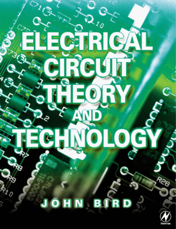
2/9/2016Transformer Losses and EfficienciesDefinition of efficiency Po2Po Pcore I L R eqWhere: Po transformer output powerPcore transformer core losses (from Open Circuittest)IL load current (primary or secondary)Req total equivalent coil resistance (referred toprimary or secondary (from Short Circuit test)Efficiencies range from 96 -99% for large power transformersLesson 10 et332b.pptx29Transformer Testing-Open CircuitTestOpen circuit test finds Rfe and Xm - core losses and magnetizingreactanceTest Set-up and conditionsP wattmeterA ammeterV voltmeterTest performed on low voltage side with H.V. side open circuited.Voc rated low side voltage. Measure: Ioc, Pc and VocLesson 10 et332b.pptx3015
2/9/2016Transformer Testing-Open CircuitTestCircuit Model Formulas for Finding Rfe and XMParallel circuit so Voc appliedacross both elementsR feLS VocI feorR feLS VocPc2X MLS VocIMLS indicates that values determined on the low voltage sideLesson 10 et332b.pptx31Transformer Testing-Open CircuitTestValues found from open circuit test:Pc core loss powerVoc open circuit voltageIoc open circuit currentFind the active part of the current from the power and voltage readingsI fe Find reactive current andcompute the value of XMPcVocR feLS VocPc2I M Ioc Ife2X MLS Lesson 10 et332b.pptx2VocIM3216
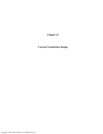
2/9/2016Open-Circuit Test ExampleExample 10-6: An Open circuit test is performed on the240 V windings of a 7200-240 V power transformer. Thefollowing data are recorded for the test Voc 240 V Ioc 16.75 A Pc 580 W. Calculate the exciting resistanceand reactance.Lesson 10 et332b.pptx33Transformer Testing-Short Circuit TestShort circuit test finds the total winding resistance and leakagereactance for both coils referred to the side on which the test isperformed (usually H.V.)Test Set-up and ConditionsShort circuit L.V. Side. Adjust the source voltage on H.V side untilrated H.V. current flows. NOTE: START WITH SOURCE V ATZERO. Measure: Vsc, Isc and PscLesson 10 et332b.pptx3417
2/9/2016Transformer Testing-Short Circuit TestCircuit model for finding Req and Xeq.Formulas for finding ReqHS and XeqHSZeqHS R eqHS j XeqHSZeqHS VscIscR eqHS The values of R and X arefound using H.V. side valuesand can be referred to theL.V. side by dividing by a2Psc2IscX eqHS ZeqHS R eqHS22Lesson 10 et332b.pptx35Short Circuit Test ExampleExample 10-7: The test data for a 75 kVA 7200 - 480 V single phasetransformer are listed below:Open-Circuit Test(Low side data)Voc 480 VIoc 16.5 APoc 558 WShort-Circuit Test(High side data)Vsc 173.1 VIsc 16.3 APsc 1200 WDetermine:a) the core resistance and reactance, the equivalent winding resistanceand reactance and draw the equivalent circuit of the transformerb) the per unit values of the values found in part a.)c) the efficiency of the transformer when operating at rated load and0.85 lagging power factor.Lesson 10 et332b.pptx3618
2/9/2016Example 10-7 Solution (1)Compute parameters from S.C. testLesson 10 et332b.pptx37Example 10-7 Solution (2)Transformer schematic showing all parametersb) Find the per unit values of all circuit componentsOn primary sideLesson 10 et332b.pptx3819
2/9/2016Example 10-7 Solution (3)Compute P.U. values using ZbaseOn secondary sidec) Find the efficiency at rated loadLesson 10 et332b.pptx39Example 10-7 Solution (4)Use primary side voltageLesson 10 et332b.pptx4020
2/9/2016Example 10-7 Solution (5)d) Find the %VRCore R and XM do not contribute to voltage drop. Use simplified model.Lesson 10 et332b.pptx41Example 10-7 Solution (6)Lesson 10 et332b.pptx4221
2/9/2016ET 332b Ac Motors, Generators and Power SystemsEND LESSON 10:TRANSFORMERPERFORMANCE ANDOPERATIONLesson 10 et332b.pptx4322
Transformer Voltage Regulation Lesson 10_et332b.pptx 5 Example 10-1: A 500 kVA 7200 - 2400 V single-phase transformer is operating at rated load with a power factor of 0.82 lagging. The total winding resistance and reactance values referred to the high voltage side are R eq 0.197 and X