Transcription
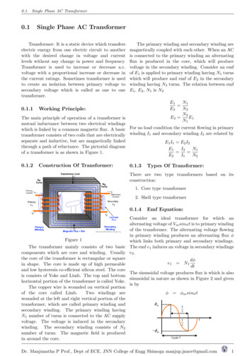
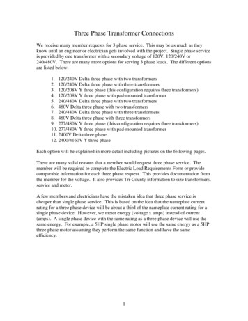
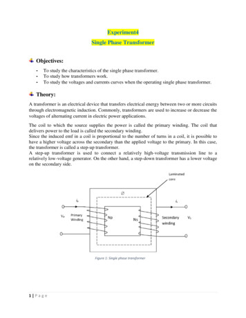
Experiment4Single Phase TransformerObjectives:-To study the characteristics of the single phase transformer.To study how transformers work.To study the voltages and currents curves when the operating single phase transformer.Theory:A transformer is an electrical device that transfers electrical energy between two or more circuitsthrough electromagnetic induction. Commonly, transformers are used to increase or decrease thevoltages of alternating current in electric power applications.The coil to which the source supplies the power is called the primary winding. The coil thatdelivers power to the load is called the secondary winding.Since the induced emf in a coil is proportional to the number of turns in a coil, it is possible tohave a higher voltage across the secondary than the applied voltage to the primary. In this case,the transformer is called a step-up transformer.A step-up transformer is used to connect a relatively high-voltage transmission line to arelatively low-voltage generator. On the other hand, a step-down transformer has a lower voltageon the secondary side.Figure 1: Single phase transformer1 Page
Construction of a TransformerIn order to keep the core loss to a minimum, the core of a transformer is built up of thinlaminations of highly permeable ferromagnetic material such as silicon-sheet steel. Silicon steelis used because of its properties and low magnetic losses.In all types of transformer construction, the central iron core is constructed from of a highlypermeable material made from thin silicon steel laminations. These thin laminations areassembled together to provide the required magnetic path with the minimum of magnetic losses.The resistivity of the steel sheet itself is high, thus reducing any eddy current loss by making thelaminations very thin.Figure 2: thin laminations from steelFirstly// Ideal TransformerA two-winding transformer with each winding acting as a part of a separate electric circuit. LetN1, and N2 be the number of turns in the primary and secondary windings.Figure 3: ideal transformer2 Page
Let us first consider an idealized transformer in which there are no losses and no leakage flux. Inother words, we are postulating the following:1- The core of the transformer is highly permeable.2- The core does not exhibit any eddy-current or hysteresis loss.3- All the flux is confined to circulate within the core.4- The resistance of each winding is negligible.A transformer turns ratio (a):The total induced voltage in each winding is proportional to the number of turns in that windingand the current is inversely proportional to both voltage and number of turns.E1: primary voltageI1: primary currentE2: secondary voltageI2: secondary currentN1: primary turnsN2: secondary turnsa: turns ratioa 𝑁1𝑁2 𝑉1𝑉2 𝐼2𝐼1Secondly//A Non-ideal TransformerPractical transformers can be called non ideal transformer because not all of the magnetic fluxproduced by the primary winding will link with the secondary winding can be losses induced withintransferring power from primary to secondary. Winding ResistancesHowever small it may be, each winding has some resistance. Nonetheless, we can replace a non-idealtransformer with an idealized transformer by including a lumped resistance equal to the windingresistance of series with each winding. As shown in Figure 4, R1 and R2 are the winding resistances ofthe primary and the secondary.Figure 4: An ideal transformer with winding resistances3 Page
Leakage FluxesNot all of the flux created by a winding confines itself to the magnetic core on which the winding iswound. Part of the flux, known as the leakage flux, does complete its path through air.Figure 5: Transformer with leakage fluxes.XI and X2 are the leakage reactances of the primary and secondary windings as shown in figure 6.Figure 6: An ideal transformer with winding resistances and leakage fluxes Finite PermeabilityThe core of a non-ideal transformer has finite permeability and core loss, known as theexcitation current from the source Iⱷ, is the sum of two currents: the core-loss current Ic andthe magnetizing current Im.Iⱷ Ic ImThe core-loss component of the excitation current accounts for the magnetic loss (thehysteresis loss and the eddy-current loss) in the core of a transformer, RC is the equivalentcore-loss resistance, Xm called magnetizing reactance can be represent the magnetizingcomponent of the excitation current.Figure 7: Equivalent circuit of a transformer including winding resistances, leakage reactance,core-loss resistance, magnetizing reactance, and an ideal transformer4 Page
Exact equivalent circuit:Figure 8The exact equivalent circuit as viewed from the primary sideFigure 9 The exact equivalent circuit as viewed from the secondary side Approximate Equivalent Circuits:Figure 10: Approximate equivalent circuit of a transformer as viewed from the primary sideFigure 11: Aapproximate equivalent circuit of a transformer as viewed from the secondary side5 Page
Experimental Procedures:You can find transformer turns ratio (a) by two methods:1- Transformation voltage ratio2- Transformation current ratioFind the turn’s ratio between nodes 1, 2 primary side and nodes 3, 4 secondary side.Part1 : Determine the turn’s ratio using voltage ratio1- Connect the circuit as shown in figure below.Figure 12 Determine the turn’s ratio using voltage ratio2- Open data table window and record data step by 10% from 0% - 100%Figure 13 Data table for voltage ratio6 Page
3- Open graph window from data table to find slope of the line between E1 at Y-axis and E2at X-axis.Figure 14 Graph window for voltage ratio4- Find slope of the line from figure above.a 12 11232 0.55Part2: Determine the turn’s ratio using current ratio1- Connect the circuit as shown in figure below.Figure 15 Determine the turn’s ratio using current ratio7 Page
2- Open data table window and record data step by 10% from 0% - 100%Figure 16 Data table for current ratio3- Open graph window from data table to find slope of the line between I2 at Y-axis and I1at X-axis.Figure 17 Graph window for current ratio4- Find slope of the line from figure above.a 8 Page21 1121 0.55
Exercise:1- Repeat the above two methods to find transformer ratio (a) between:a) Primary side 1,2 and secondary side 5,6b) Primary side 7,8 and secondary side 5,69 Page
1 P a g e Experiment4 Single Phase Transformer Objectives: - To study the characteristics of the single phase transformer. - To study how transformers work. - To study the voltages and currents curves when the operating single phase transformer. Theory: A transformer is an electrical device that