Transcription
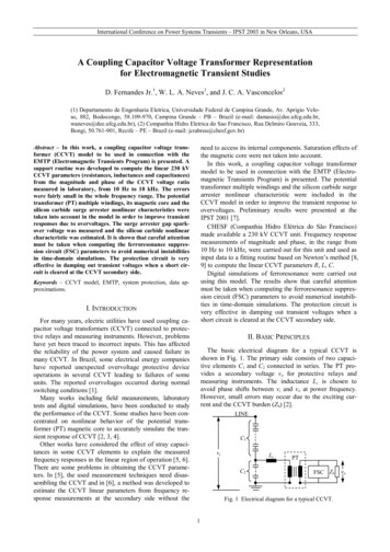
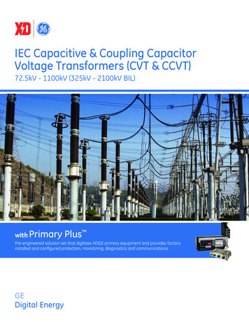
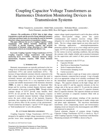
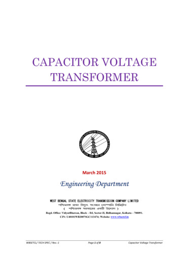
CAPACITOR VOLTAGETRANSFORMERMarch 2015Engineering DepartmentWEST BENGAL STATE ELECTRICITY TRANSMISSION COMPANY LIMITEDRegd. Office: VidyutBhawan, Block – DJ, Sector-II, Bidhannagar, Kolkata – 700091.CIN: U40101WB2007SGC113474; Website: www.wbsetcl.inWBSETCL/ TECH SPEC / Rev.-1Page 1 of 8Capacitor Voltage Transformer
TECHNICAL SPECIFICATION FOR CAPACITOR VOLTAGE TRANSFORMER1. SCOPE :This section covers design, manufacture, assembly and testing at the manufacturer’s works, supply,delivery at site of 420KV, 220KV & 132KV CVT complete with fittings and accessories. The CVTs shallsupply voltage for metering, synchronizing and relaying services in 3-phase solidly grounded systemand shall also be used for communication, teleprotection, telemetering and for line synchronization.2. STANDARDS :Capacitor Voltage Transformers and accessories covered by this specification shall comply with therequirements of the latest edition of the IS/IEC standards. In the event of the equipment confirm toany other internationally recognized standards which ensure better or equivalent quality areacceptable. Salient points of comparison shall be clearly brought out in the bid and a copy of thestandard in English language shall be submitted.3. DEVIATION :Normally the offer should be as per Technical specification without any deviation. But any deviationproposed must be mentioned in the “Deviation Schedule” with reasons and advantage of suchdeviation. Deviations not mentioned in “Deviation Schedule” will not be considered afterwards. Suchdeviation may or may not be accepted.4. CONSTRUCTION :The features and constructional details of the capacitor voltage transformers shall be in accordancewith the requirement stipulated hereunder:a) Capacitor Voltage Transformers shall be complete in all respects and shall conform to the modernpractice of design and manufacture.b) Capacitor Voltage Transformers shall be outdoor type, single-phase, 50 Hz, housed in 220KV &132KV class, oil filled, self-cooled shaded porcelain bushing suitable for operation under theservice conditions as specified in general condition of service without protection from sun, rainand dust.c) Capacitor Voltage Transformers shall be suitable for upright mounting on steel structures andshall preferably be suitable for horizontal transportation. The bidder shall also offer suitable steelpedestal/stand for CVTs and other outdoor equipment i.e Coupling devices etc and the standshould have a minimum height of 2500 mm.WBSETCL/ TECH SPEC / Rev.-1Page 2 of 8Capacitor Voltage Transformer
d) The capacitor voltage transformers shall be complete with accessories like terminal connector forprimary connection, weather proof terminal box for secondary connection, lifting lugs, groundingterminals, oil sight glass, filling and draining plugs and name plate.e) The capacitor voltage transformers shall be filled up with insulating oil having characteristic asper latest IS:335 as specified. Capacitor Voltage Transformers shall be hermetically sealed toeliminate breathing and to prevent ingress of air and moisture into the capacitor stack and intothe tank of Capacitor Voltage Transformer. The tank shall have a built-in-provision to dissipateany excessive internal pressure.f) The capacitor voltage transformers shall consist of coupling capacitive dividers andelectromagnetic units and shall be suitable for coupling the carrier equipment to the 220KV &132KV overhead lines.g) The coupling of Capacitor Voltage Transformers shall be suitable for the entire carrier frequencyrange of 40 KHz to 500 KHz. Necessary arrangement for preventing the HF signal to flow to theother circuits shall be provided.h) The capacitor divider may consist of primary and secondary capacitance.i) The capacitor voltage transformers shall have two secondary windings, one of which are intendedfor protection and the other one for metering.j) Material for Primary and Secondary winding shall be of Copper.k) The Capacitor voltage transformer secondary shall be protected by HRC cartridge type fuses forall the windings.l) The HF terminal shall be kept earthed when not used for PLCC purpose. Earthing link withfastener to be provided for HF terminal.m) Capacitor Voltage Transformers shall be suitable for high frequency (HF) coupling required forpower line carrier communication.n) Connection between coupling device and CVT shall be done by means of 6sq. mm copper wiretaped with 11KV insulation5. TEMPERATURE RISE : The maximum permissible temperature rise of the capacitor voltage transformer windings at 1.2times rated primary voltage, rated frequency and rated burden corresponding to the highestrated output at any power factor between 0.8 and unity, over an ambient temperature of 50ºCshall not exceed the limits as specified in IEC standards.The temperature rise at 1.5 times rated primary voltage when supplied for 30 seconds starting atstable thermal conditions achieved by supplying 1.2 times the rates voltage continuously shall notexceed by more than 10ºC the values specified in the clause above.For any ambient temperature above the reference ambient temperature, the permissibletemperature rise shall be reduced by an amount equal to excess ambient temperature.6. BUSHING OF CVT:a) The bushing shall have insulation, mechanical strength and rigidity for the condition under whichthen will be used at site and shall be designed to prevent accumulation of explosive gases andprovide adequate oil circulation to remove internal heat.b) There shall be no undue stressing of any part of the bushing due to temperature change andadequate means shall be provided to accommodate conductor expansion.c) The bushing shall not cause any radio interferences when operated at rated system voltage.d) All ferrous parts of the bushing including lifting hooks, cast metal end caps, bolts, nuts etc. usedon the bushing shall be of high strength and hot dip galvanized as per IS:2633 as amended up todate.WBSETCL/ TECH SPEC / Rev.-1Page 3 of 8Capacitor Voltage Transformer
e) Porcelain used, shall be homogenous, free from laminations, cavities and other flaws orimperfections that might affect the mechanical or dielectric quality and shall be thoroughlyvitrified, tough and impervious to moisture.f) The glazing of porcelain shall be of uniform brown or dark brown colour, free from blisters, burnsand other similar defects and shall have smooth surface arranged to shed away rain water. Theporcelain shall have ample insulation, mechanical strength and rigidity for the conditions underwhich they will be used.g) The insulation of the porcelain shall be coordinated with that of the capacitor voltagetransformers such that the flash over, if any, will occur only external to the voltage transformer.h) The porcelain shell of the bushing shall be as per IS:5621 or IEC:815.i) The porcelain shed shall be alternate long and short as per IEC:815.j) Capacitor Voltage Transformers must withstand mechanical stresses resulting from wind pressureof 150Km per hour.7. INSULATING OIL :The quantity of insulating oil for filling complete unit shall be stated and the insulation oil shall complyin all respects with the provisions of the latest edition of IS:335 or IEC Publication 296 (as amendedup-to-date).8. TERMINAL CONNECTORS :a) Capacitors Voltage Transformers shall be supplied with primary terminal connector suitable toconnect twin Moose ACSR/approved drawings Conductor.b) The terminal connectors should conform to the respective specification for clamps andconnectors.9. GROUNDING TERMINALS :Two grounding terminals shall be provided on the diagonally opposite sides of the tank of eachcapacitor voltage transformer. The grounding conductor shall be MS flat of size 75 mm x 6 mm.10. SECONDARY TERMINAL BOX :i)All secondary terminals of the capacitor voltage transformers shall be brought out in a weatherproof terminal box provided at one side of each voltage transformer for easy access. CVT sec.terminal box shall be made of sheet steel having minimum thickness of 3 mm. However, 2 mm.thickness having powder coated painting is acceptable.ii) The terminal box shall be hot-dip galvanized/painted.iii) The terminal box shall be provided with a removable cable gland plate at the bottom formounting three cable glands suitable for 1100V grade, steel wire armoured, PVC sheathed 4 x 2.5sq. mm. stranded copper conductor cables. The cable glands shall be included within the scopeof supply and shall be screw on type and made of brass.WBSETCL/ TECH SPEC / Rev.-1Page 4 of 8Capacitor Voltage Transformer
iv) The terminal box shall be provided with a door on the front so as to permit easy access tosecondary terminals. The door shall be provided with locking arrangement to prevent ingress ofmoisture and water into the terminal box.v) The terminal box shall be provided with a terminal board. The terminals shall be so staggeredthat connection of external cable to any terminal block should be possible without disturbing therest of the connections. The terminal block arrangements shall be such as to provide maximumaccessibility to all conductor terminations.vi) The terminal blocks shall be fully enclosed and made of moulded, non-inflammable plasticmaterial and barriers moulded integrally.vii) Terminal block arrangements shall be such that it will be possible to connect or disconnectterminals on live circuits.viii) All terminals shall be clearly marked with identification number to facilitate connection to externalwiring.ix) One secondary terminal other than three winding shall be connected through impedance to avoidferroresonance.x) A protective surge arrester shall be provided to prevent breakdown of insulation by incomingsurges and to limit abnormal rise of terminal voltage of shunt capacitor/primary winding, tuningreactor/RF choke etc. due to short circuit in transformer secondaries. In case of an alternatearrangement, bidder shall bring out details in the bid.11. NAME PLATE :Capacitor Voltage Transformers shall be provided with name plate. Name plate shall conform to therequirements of the relevant IEC incorporating the year of manufacture.12. PAINTING :i)The tank shall either be hot dip galvanized or painted. All steel surfaces shall be cleaned by sandblasting or chemical process as required to produce a smooth surface, free of scale, grease anddirt. Steel surfaces in contact with insulating oil shall be painted with heat resistant oil insolubleinsulating varnish.ii) External surfaces shall be given a coat of high quality red or yellow chromate primer and finishedwith two coats of synthetic enamel paints (Light gray as per shade 631 of IS:5).iii) Paints shall be carefully selected to withstand tropical heat, rain etc. The paints shall not scale offa crinkle or be removed by abrasion due to normal handling.13. CONTRACT DRAWING AND MANUALS :After placement of Purchase Order or Letter of Award (LOA) the contractor shall submit six (6) copiesof drawing/catalogue to the Chief Engineer, Tr. Project, Vidyut Bhavan, 10th floor, Salt Lake, Kolkata –91 for approval.i)Outline general arrangement dimensional drawing of Capacitor Voltage Transformer furnishingfront and side elevations, top and bottom plan views, cross sectional view, all accessories andexternal feature, mounting arrangement on steel structure, spacing and size of the mountingbolts, total and protective creepage distance of the bushing, internal circuit diagram with polaritymarks, terminal arrangement for secondary terminal box, size of primary terminals, groundingWBSETCL/ TECH SPEC / Rev.-1Page 5 of 8Capacitor Voltage Transformer
ii)iii)iv)v)vi)terminals and lifting lugs, quantity of insulating oil, net and shipping weights, shipping dimensionsetc.Name and rating plate diagram of the Capacitor Voltage Transformers.Foundation and anchor details including dead load and impact load with direction and point ofapplication and also location of Centre of Gravity of CVT.Technical catalogue, operation and maintenance manual.Any other drawings found necessary in addition to those stated above.Ten(10) sets of approved drawings and ten(10) copies of erection, operation and maintenancemanual for the capacitor voltage transformers in English language shall be submitted for eachsubstation for our record and distribution to site. The manual shall contain the following :a) A brief description of Capacitor Voltage Transformers furnishing the constructional features.b) Operation and maintenance of Capacitor Voltage Transformers.c) Outline general arrangement drawing of Capacitor Voltage Transformers furnishing all thecomponents and accessories.d) Marked erection prints identifying the component parts of Capacitor Voltage Transformers.e) Detailed dimensions, assembly and description of all the accessories.f) Diagram plate, internal circuit diagram of the component parts of the CVT’s and terminalarrangement of the secondary terminal box.g) Any other information found necessary in addition to those stated above.h) In all drawings reference of L.O.A. No. shall be mentioned.14. TEST AT FACTORY AND TEST CERTIFICATES :The following acceptance test shall be carried out on every lot of Capacitor Voltage Transformersoffered for inspection as per latest edition of IS:3156 (Part I to IV) and IEC:358. The entire cost ofacceptance and routine test that are to be carried out as per relevant IS & IEC shall be treated asincluded in quoted price of CVT. Six copies of test reports shall be submitted to the Chief Engineer,Tr. Project, Bidyut Bhavan, 10th floor, Salt Lake, Kolkata-700091 for approval and adequate extracopies for distribution at site. The contractor shall give at least 21 (twenty-one) days notice inadvance of the date when the test will be carried out. Six(6) copies of routine test results ofcapacitor voltage transformer shall be submitted to the Chief Engineer, Engineering, for approval.i) Verification of terminal markings and polarity as per clause 15 of IEC:186 as amended up to date.ii) Pow
f) The capacitor voltage transformers shall consist of coupling capacitive dividers and electromagnetic units and shall be suitable for coupling the carrier equipment to the 220KV & 132KV overhead lines. g) The coupling of Capacitor Voltage Transformers shall be suitable for the entire carrier frequency range of 40 KHz to 500 KHz. Necessary arrangement for preventing the HF signal to flow to theFile Size: 613KBPage Count: 8People also search forvoltage transformervoltage transformer diagram pdfvoltage transformer pdfvoltage transformer pddhow a transformer works
