Transcription
NFV-VITAL: A Framework for Characterizing thePerformance of Virtual Network FunctionsLianjie Cao , Puneet Sharma , Sonia Fahmy† , Vinay Saxena‡Packard Labs † Purdue University ‡ Hewlett Packard Enterprisee-mail: {lianjie.cao, puneet.sharma, vinay.saxena}@hpe.com, fahmy@purdue.edu HewlettAbstract—Network Function Virtualization (NFV) brings acloud service automation paradigm to demand-driven elasticflexing of infrastructure resources. Thus, it is essential to characterize the impact of hardware and virtualization options on thevirtual network function (VNF) performance, and on the load onunderlying infrastructure.In this paper, we present VNF characterization case studieswith three sample open-source VNF platforms, the ClearwaterIMS VNF and two intrusion detection system VNFs (Snort andSuricata). We demonstrate that VNF characterization is vital foroptimizing VNF performance, as well as efficient utilization ofinfrastructure resources. We use the lessons learned from ourcase studies to design and implement a VNF characterizationframework, NFV-VITAL, to characterize VNFs based on userpreferences and available resources. We demonstrate how NFVVITAL can automatically determine optimal configurations underdifferent workloads with the three sample VNFs.I.I NTRODUCTIONDriven by the requirements for faster provisioning ofnetwork services, Communication Service Providers (CSPs)have embarked on a major transformation of their networkinfrastructure by adopting Network Function Virtualization(NFV) [1]. NFV entails implementing network functions –currently available on proprietary middleboxes and networkequipment hardware – in software. Such Virtual NetworkFunctions (VNFs) can be deployed on industry standard commodity servers, storage and switches. NFV allows CSPs toleverage virtualization and cloud automation technologies. Aswith the “Cloudification of IT services,” the NFV transformation not only enables agile network service deployment,but also improves demand-driven elastic flexing for scale-out,and breaks the hardware vendor lock-in as VNFs are portableacross different hardware platforms.Several challenges need to be tackled for successful NFVdeployment. First, the network equipment providers shouldkeep the performance degradation from software implementation of network functions to a minimum. Second, the NFVorchestration tools need to determine the virtualization setups and configuration options to optimize VNF performanceand automatically scale the VNF resource allocation withworkload. Third, a unified interface for decoupling virtualizedinstances from underlying hardware is needed. Although understanding the impact of virtualization on network functionsis of paramount importance for NFV to succeed, currentstudies are driven by vendor efforts to demonstrate eitherthe overhead associated with their respective technologies,or the performance of their respective VNF implementations.Performance studies of NFV fall into three broad categories:(i) Performance benchmarking of a single option, such as CPUpinning, Intel DPDK, PF RING, and SR-IOV, e.g., [2], [3], (ii)Performance testing of a single VNF running on a hypervisorin an isolated environment, e.g., [4], and (iii) Network performance measurement, such as UDP/TCP throughput and delay,of a VM or a public cloud deployment, e.g., [5].One difficulty in creating an NFV characterization framework is the large number of configuration knobs and hardwaresettings (e.g., CPU pinning, c-states, and memory interleaving)available in NFV deployments. Additionally, the computeand network requirements of various VNFs vary significantly.While VNFs such as virtual routers and firewalls are primarilybounded by network throughput, others such as load balancersare bounded by network and compute (or memory) for sessionstate management. Some VNFs may comprise multiple simplerVNFs/components with a communication and dependency relationship among them. Each of these components can exhibitdifferent virtualization impacts and scalability requirements.This paper makes two key contributions. First, we conducta VNF case study on the Clearwater [6] cloud-based IPMultimedia Subsystem (IMS) (section II). Motivated by thiscase study, we propose NFV-VITAL (Virtualization Impact onThroughput And Load) – a framework for performance characterization of different types of VNFs in a real private clouddeployment (OpenStack) with different options (e.g., CPUpinning) (section III). We demonstrate the benefits of the NFVVITAL framework for analyzing optimal sizing and configuration for the Clearwater, Snort, and Suricata VNFs. NFV-VITALcan be used for automatically: (1) Estimating VNF capacity fora given resource configuration, (2) Computing virtualizationand system overhead associated with resource flexing such asscale-out and scale-up, (3) Determining the optimal resourceconfiguration for a given workload, (4) Evaluating differentvirtualization and hardware options, and (5) Fine-tuning VNFimplementation and performance.II.C ASE S TUDYBefore designing NFV-VITAL, we conduct a case study tounderstand how different orchestration/scaling methods affectthe performance of a clustered VNF with different components. We seek answers to questions such as (1) how VNFperformance varies when allocating the same resources indifferent setups; (2) causes for the differences: load balancing,inter-component synchronization or intra-component communication; (3) how to alleviate performance degradation withdifferent orchestration methods; (4) how to detect when a VNFis approaching a performance bottleneck; and (5) how best toscale the system to achieve the highest performance gain. With
these answers, we can derive the characterization frameworkin section III.orchestration strategies. We collect the CPU, memory andnetwork usage of all instantiations for deeper analysis.We construct a testbed with 3 HP DL360p blade serversand 2 HP Z420 workstations, connected by an HP ProCurve3500yl Gigabit switch. Table I gives the basic configurationof the testbed machines. We use the OpenStack [7] Icehouserelease as a cloud orchestrator to manage the compute andnetwork resources. The 3 DL360p blade servers are used ascompute nodes (CNs) and the two Z420 workstations areused as controller and network nodes (NN), respectively. TheOpenStack networking component is configured with ModularLayer 2 (ML2) GRE tunnels. All tests in this paper areconducted on this testbed.1) Workload Generation: We use the open source toolSIPp [10] as the workload generator, and choose user registration and deregistration as a test scenario. Each SIPp reg-deregcall contains three REGISTER requests – the first two are forregistration and authentication and the third is for deregistration. If any of the three requests yields an unexpected response(e.g., 408 Request Timeout and 503 Service Unavailable), thecall is considered as “failed.” If a request does not receive anyresponse in 10 seconds, this call also fails due to timeout.TABLE I: Blade server, workstation and VM 1.largeCPU2x Intel Xeon E5-2680 v21x Intel Xeon E5-16201x vCPU2x vCPU4x vCPUCores204124RAM212 GB16 GB2 GB4 GB8 GBA. Clearwater: An IP Multimedia Subsystem VNFClearwater [6] is a real world, telco-grade IP MultimediaSubsystem (IMS). 1 It is a typical clustered VNF that comprises a number of components, each of which plays a uniquerole in the system and exhibits unique resource utilizationpatterns: Bono is the SIP edge proxy component, providingboth a SIP IMS Gm compliant interface and a WebRTCinterface to clients. Sprout serves as combined SIP registrarand authoritative routing proxy, and handles client authentication and interfaces to other application servers. Homesteadis the home subscriber server with web interfaces provided toSprout for retrieving authentication credentials and user profileinformation. Homer is a standard XML document managementserver that stores multimedia telephony service settings foreach user. Ralf is used for offline billing. Ellis is a sampleweb-based user provisioning portal for self sign-up, passwordmanagement, line management and control of service settings.Our lab deployment of Clearwater excludes Ralf and Ellis,since these two components are for billing and account management which are not key for our characterization case study.Each of the deployed components consists of one or more VMsof different sizes orchestrated by OpenStack. A separate VMis used as a DNS server for internal communication and loadbalancing in clustered deployments of Clearwater.Sprout and Homestead use memcached [8] and cassandra [9] to store registration state and user information, respectively. Therefore, clustering these two components involvessynchronization of the datastore and timer service. As the SIPedge proxy, each Bono node works independently without anysynchronization with other Bono nodes. All Clearwater VMsare assigned to the same compute nodes of OpenStack andeach vCPU is pinned to a physical core to eliminate potentialeffects of network and CPU dynamics.SIPp runs on a dedicated physical server. We change thecall rate with a granularity of 50 calls/sec from 200 calls/secto 1100 calls/sec depending on the deployment size. Each testlasts 300 seconds and we repeat it 10 times to average theresults.2) System Capacity Measurement: The definition of VNFcapacity may vary depending on the functionality of the VNFand type of workload. In our study of the Clearwater IMS,the most important metric is the maximum offered workloadat which it can provide the desired stable service. We measurethis by monitoring how closely the successful call rate (SCR)reported by SIPp follows the input call rate (ICR) we specifyin SIPp. Both quantities are in units of calls per second.Clearwater uses a token bucket mechanism [11] to controlthe load. It accepts a request only if the token bucket is nonempty. The token bucket is replenished based on a token ratethat is adjusted as follows. If current message queuing delayhas not reached a predefined threshold value, the token rateincreases additively; otherwise it decreases multiplicatively:ICR message queuing time token rate reject requests SCR Therefore, we define Clearwater system capacity with regdereg traffic to be the maximum ICR when SCRICR a specifiedthreshold, e.g., 0.8 or 0.9. In other words, when reg-dereg callrate exceeds the system capacity, a certain percentage, say 10or 20%, of the calls will fail.C. ResultsBased on our observations, Bono, Sprout and Homesteadare the three most heavily loaded Clearwater componentsand they are all CPU-bound in single VM per componentinstantiation. In our tests, we change the total number ofvCPUs assigned to the Clearwater cluster and evenly distributethem among the three components. Homer uses one smallinstance in all tests. Therefore, in the rest of the analysis, wefocus on CPU usage analysis of Clearwater instances. We didnot cluster Bono nodes due to the observation that Bono nodeswork independently without any synchronization overhead andit is not the bottleneck in any of our tests.B. Testing MethodologyWe vary the workload and the deployment size of Clearwater (scaling up/down, in/out) to understand the impact of1 Clearwater is still under active development (released twice a month).Different versions may exhibit different performance.Table II shows the deployment sizes we tested and themaximum ICR when SCRICR is 0.8 and 0.9. The columnSCR 0.9givesthesystemcapacities. In the remainderICRof this section, we discuss the results using different scalingmethods.
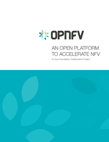
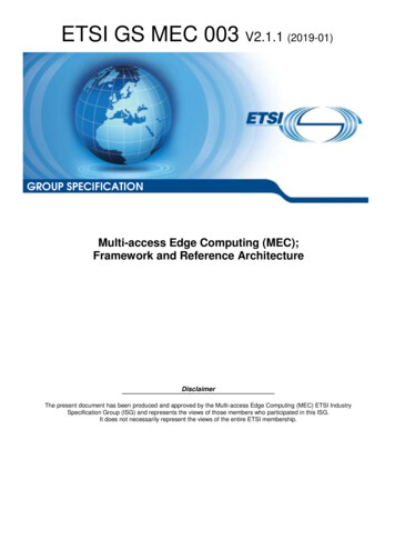
TABLE II: Clearwater system capacity using different scalingmethods. bn1s-sp1s-hs1s stands for one small instancefor Bono, 1 small instance for Sprout and 1 small instance forHomesteadClearwater 0500350ICR(0.8)3506503501100650650500450500450(a) bn1m-sp1m-hs1m1) Scaling Up: To test Clearwater scaling up, we use oneinstance per component and increase the size of instances fromsmall to large (e.g., bn1s-sp1s-hs1s, bn1m-sp1m-hs1mand bn1l-sp1l-hs1l in table II). Fig. 1 shows the SCRchanges as ICR increases.(b) bn1m-sp2s-hs2sFig. 1: Clearwater: scaling upFor the same deployment size, SCR changes significantly when ICR exceeds the system capacity point ofSCR 0.9, which means that Clearwater can no longerprovide stable service beyond that point. Scaling up Clearwater by doubling the CPU resource almost doubles thesystem capacity. For instance, when Clearwater scales frombn1s-sp1s-hs1s to bn1m-sp1m-hs1m, the system capacity increases from 350 calls/sec to 600 calls/sec, and scalingfurther to bn1l-sp1l-hs1l boosts system capacity to 1000calls/sec.Fig. 2a shows SCR and CPU usage in test casebn1m-sp1m-hs1m collected from the SIPp report and utilization traces at three different workload levels: underload,system capacity and overload. Additional plots are availablein [12]. We found that both SCR and CPU utilization oscillatesignificantly when the workload exceeds the system capacitypoint. This is due to the Clearwater load control mechanismon the Sprout instance, which rejects requests when it detectsthat the request queuing time exceeds a given latency (e.g.,100 ms). CPU resources are freed during this load adjustingperiod and SIP requests are not handled. This situation canoccur on all instances of Sprout and Homestead when theCPU usage approaches 100%. In other words, this instancemay become the bottleneck of the entire Clearwater system.2) Scaling Out: We investigate scaling out by increasingthe number of instances for different components. We compared Clearwater deployment sizes from 1 small instance perFig. 2: SIPp statistics and CPU utilization for bn1m-sp1mhs1m and bn1m-sp2s-hs2s. Blue, red and green curvesstand for CPU usage of Bono instance, Sprout instances andHomestead instances respectively.component to 4 small instances per component or 2 mediuminstances per component (e.g., bn1s-sp1s-hs1s, bn1msp2s-hs2s, bn1l-sp2m-hs2m and bn1l-sp4s-hs4s)shown in fig. 3. Scaling out from bn1s-sp1s-hs1s tobn1m-sp2s-hs2s does not improve the performance ofClearwater even when the total CPU resource assigned toClearwater is doubled. Scaling out further to bn1l-sp2mhs2m and bn1l-sp4s-hs4s improves the performance, butit is still significantly less than the base case bn1l-sp1lhs1l with equivalent vCPU resources.Fig. 3: Clearwater: scaling outCompared to scaling up, scaling out does not increaseClearwater system capacity due to two key reasons: (1) Datasynchronization among nodes of the same component: In
Clearwater, this includes synchronization of chronos and memcached on Sprout nodes and cassandra on Homestead nodes.chronos is a synchronized timer service to track registrationexpiry information on different Sprout nodes; and (2) Imperfectload balancing: Bono creates 50 connections to all Sproutinstances, and these connections get refreshed every minutefollowing a Poisson distribution. If too many rejections (503response) occur on one specific Sprout node, this Sprout nodeis blacklisted by Bono for several periods. Therefore, thisSprout node becomes idle. Hence we conclude that, Clearwaterdoes not always benefit from more CPU resources, whichresults in the imbalance of CPU usage we observed on differentSprout nodes in Fig. 2b. This does not occur when allocatingall CPU resources to one instance in the scaling up tests. Theblacklisting combined with per instance load control make loadbalancing ineffective.3) Hybrid Scaling: The goal of hybrid scaling is to isolate clustering impact from different components using thesame amount of CPU resources. For instance, Sprout clusters memcached, while Homestead clusters cassandra. Wecompared bn1l-sp1l-hs2m to bn1l-sp2m-hs1l, andbn1l-sp4s-hs1l to bn1l-sp4s-hs4s, all of which use12 vCPUs. As shown in fig. 4, Clearwater exhibits worseperformance when clustering more and smaller instances,compared to fewer and larger instances. Clustering differentcomponents changes the performance patterns as workloadincreases. For instance, SCR shows flatter reduction whenclustering Homestead, while it drops suddenly after reachingthe system capacity point when clustering Sprout.Fig. 4: Clearwater: hybrid scalingIII.F RAMEWORK D ESIGNMotivated by our case study in section II, we believe thatan NFV performance characterization framework should: (1)accommodate different types of VNFs, (2) adapt the deployment size of a VNF, with awareness of VNF components,(3) generate different VNF workloads, (4) collect resourceutilization traces of VNF instances, and (5) generate VNFperformance evaluation reports.The aim of NFV-VITAL is to quickly determine theconfiguration yielding maximum performance of a VNF. Thisposes the following challenges: (1) how to handle differenttypes of VNFs, and (2) how to make practical and thoroughperformance testing plans for a given VNF. To generalize todifferent VNF types, NFV-VITAL allows users to plug in theirown scripts to deploy and configure a target VNF, run workloadgenerators, and specify high-level testing “hints” for differenttesting modes. Metrics vary based on the VNF. Researchersmay evaluate intrusion detection system (IDS) software interms of accuracy, throughput, or additional latency. NFVVITAL computes the relationship between the offered load andthe system throughput when varying virtualization/platformoptions and orchestration strategies. In other words, NFVVITAL computes the maximum workload a VNF can handlebefore service quality degrades, using different deploymentsizes and virtualization options.We leverage the proposed NFV architectural frameworkfrom ETSI [1] and implement NFV-VITAL as shown in Fig. 5.Fig. 5: NFV-VITAL framework architectureThe framework consists of four components: VITAL orchestrator, VNF workload generator, VNF load monitor, anduser input.User Input: As discussed above, VNFs are designed fordifferent purposes, making it difficult to unify their usage. Fortesting purposes, we classify their differences into three types:(1) installation/deployment, (2) workload generation, and (3)evaluation metric. To bridge these differences, NFV-VITALallows users to provide their own deployment specificationand workload specification files, both of which are in jsonformat. Deployment specifications include VNF informationsuch as vnf name, components, instances, flavors,servers, install, and mode. flavors are the VMsizes to test and server includes user preferences whenchoosing hosts for VNF instances, such as the preferrednumber of servers and virtualization features. mode gives thetesting mode for the target VNF, which we will discuss insection III-A. The workload specification instructs the VNFworkload generator on different rates, stop, generatorand repeat values. Examples and detailed explanations ofuser input can be found in [12].VITAL Orchestrator: The VITAL orchestrator generates Heattemplates [13] that represent the deployment sizes that theframework will test. The VITAL orchestrator uses each Heattemplate to start all instances specified and then runs the giveninstallation script to bootstrap the VNF. After deployment iscomplete, it invokes the VNF workload generator to initiatethe testing process.The orchestrator also executes a daemon process to receiveand manage resource utilization traces from the VNF loadmonitor, and VNF performance logs from the VNF workloadgenerator. After all tests complete, system performance and resource utilization plots are generated for each test. Comparison
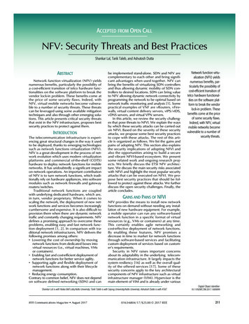
plots can be produced for all deployment sizes tested. Based onthe testing mode, the VITAL orchestrator may scan resourceutilization traces immediately after testing each deploymentsize.VNF Workload Generator: The workload generator is invoked by the VITAL orchestrator once a test deploymentis complete. The generator reads a specification file, whichincludes the name of an input script to run in order to generatethe workload(s) on the target VNF. The users specify thelocation of this script in the generator field. NFV-VITALrelies on the users to specify the range in which the workloadgenerator operates and the type of traffic to use, e.g., SIPpregistration requests. The generator starts with the minimumworkload rate given in a range field, and linearly increasesthe rate based on an increase field. The same test may berepeated several times depending on the value of a repeatfield. The VNF workload generator also expects the user scriptto return a performance indicator (e.g., SCR in Clearwatertests) to describe system performance.Since we use the same range to generate workloads forall deployment sizes, it is possible that some target VNFdeployments with small sizes reach the system capacity pointahead of reaching the maximum value in range. In this case,increasing workload further is not useful. Thus, we provide anoptional feature for the user to define a stopping condition inthe stop field. The testing process for a given deployment sizeterminates when the maximum rate is reached or the stoppingcondition is satisfied.VNF Load Monitor: Since users may not have access tophysical hosts on some platforms, the VNF load monitor runson all VNF instances to collect (i) CPU, (ii) memory, and (iii)network utilization, and record them in a csv file during atest. When a test is complete, the three utilization traces areuploaded to the VITAL orchestrator. The users can decide touse any of three utilization values for scaling.A. Testing ModesTo make practical and thorough testing plans, NFV-VITALallows users to choose from three testing modes: custom sizing,exhaustive search, and component-aware directed search.Custom Sizing: In this mode, users can specify differentdeployment sizes in the sizes field of the deploymentspecification, e.g., number and flavor of each VNF component.The VITAL orchestrator directly translates these deploymentsizes into Heat templates. A user can use this mode to test themaximum workload and the bottleneck components of specificdeployment sizes.Exhaustive Search: Exhaustive search is ideal when a userwants to test all possible deployment sizes for given resources.With exhaustive search, the VITAL orchestrator first computesall possible combinations based on the given flavors of eachVNF component that satisfy the resource requirements, thentranslates all possible sizes into Heat templates. As with custom sizing, deployment sizes to test are determined beforehandin an offline fashion.Component-aware Directed Search: An important lesson welearned from section II is that the performance of a VNFdeployment can be limited by a specific component. Thus, wedesign a component-aware directed search system to determinethe optimal deployment size for a given workload, or the maximum performance that can be reached using given resources.Unlike custom sizing and exhaustive search, the deploymentsizes in directed search are computed online during the testingprocess.The VITAL orchestrator starts with the minimal deployment size (e.g., one instance with minimum flavor per component). After tests on this initial deployment size are complete,the VITAL orchestrator analyzes the resource utilization traceswhen the system capacity point is reached, and determines theVNF component with highest resource usage. Directed searchthen scales up or out. We are still investigating the integrationof hybrid scaling in directed search to increase the searchspace. The testing process terminates either when the givenworkload is reached or when the given resource is exhausted.With exhaustive search and component-aware directedsearch, the solution space may grow exponentially as theresources and the number of components increase. However,the available VM sizes are limited, which reduces the numberof possible solutions. For instance, we only use three differentVM sizes cw1.small, cw1.medium and cw1.large inour demonstrations. For exhaustive search, since all possibledeployment sizes are computed offline, this problem doesnot affect the performance at run time. For component-awaredirected search, we limit the users to use either scaling up orscaling out in one set of tests. If the users choose scaling out,only one VM size can be defined. Therefore, the users candetermine the optimal VM size of the VNF by scaling up andthe optimal number of VMs for each component by scalingout. These strategies yield a reasonable solution space size inour evaluation.B. Framework DemonstrationsUsing NFV-VITAL, we conduct three demonstrations onClearwater and two types of IDS software: Snort and Suricata.1) Clearwater Demonstration: Unlike the Clearwater testsin section II, we use component-aware directed search in thisdemonstration. The user input file has a 6-vCPU resourcerestriction, CPU core pinning, and scaling up. This input filecan be found on our webpage (denoted in the footnotes).NFV-VITAL first tests bn1s-sp1s-hs1s and finds thatthe bottleneck is CPU usage on the Sprout component. Itthen scales up to bn1s-sp1m-hs1s adding one more vCPUto Sprout. Now Homestead CPU usage becomes the systembottleneck. NFV-VITAL then scales to bn1s-sp1m-hs1m.Sprout becomes the bottleneck again. However, we cannotscale up the Sprout instance to cw1.large because of the 6vCPU threshold we specified. NFV-VITAL then repeats thesame process using core pinning. Fig. 6 shows how SCRchanges when applying the same reg-dereg traffic. Based onthis result, we conclude that the optimal deployment size witha 6-vCPU restriction is bn1s-sp1m-hs1m and the maximumsystem capacity is 600 calls/second of reg-dereg traffic.As shown in section II, different components of Clearwaterexhibit different CPU usage patterns: Sprout is the bottleneckwith twice the CPU usage of Bono when we assign them thesame resources. However, the optimal Clearwater deployment
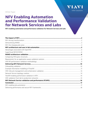
size that NFV-VITAL finds in this demonstration yields similarCPU usage for Sprout, Homestead, and Bono (75% to 85%).We also tested with reg-invite traffic, with 21 requestsand responses in each call. The optimal deployment size thatNFV-VITAL finds is also bn1s-sp1m-hs1m. The maximumsystem capacity is 150 calls/second, however. This confirmsthat with different types of traffic, the same VNF can exhibitsignificantly different system capacity.for some stateful attacks. When we increase the malicioustraffic proportion, we find that the processing speed of Snortsignificantly decreases due to the rule matching overhead.In summary, NFV-VITAL can locate the performance bottleneck of the entire VNF under different conditions. Given theresources or workload, NFV-VITAL can determine the mostefficient deployment size in an automated fashion.Fig. 7: NFV-VITAL demonstration on SnortFig. 6: NFV-VITAL demonstration on Clearwater2) IDS Demonstration: In this demonstration, we computethe packet processing ability of Snort (version 2.9.7.3) andSuricata (version 2.0.8) using custom sizing. Since both IDSsare single VNF, we test them with three deployment sizes: onesmall instance, one medium instance, and one large instance.Similar to the baseline test in [14], we keep the defaultconfiguration of both Snort and Suricata using the same VRTrule set. The only change is that we enabled the “set-cpuaffinity” option on Suricata. The test environment involvesfour VMs in the same virtual subnet running hping3 [15] togenerate UDP traffic at the same rate with packet size 64bytes. All traffic is mirrored to a separate VM running IDSsoftware. We add an additional rule to match UDP packetswith the keyword “malicious” in the payload. A VM thatgenerates traffic matching this rule is identified as a maliciousnode. We vary the number of malicious nodes from 0 to 4to generate five types of traffic: 0% malicious traffic, 25%malicious traffic, 50% malicious traffic, 75% of malicioustraffic, and 100% malicious traffic. The workload is definedby the packet generation speed from all four senders, and thesystem performance is represented by the packet processingspeed of the IDS – both quantities are in kilo-packets persecond (kpps).Fig. 7 shows how the packet processing speed on Snortchanges with increasing traffic. We observe that for the sametype of traffic, scaling the Snort instance from small to largeyields little improvement. Investigating the resource utilizationtraces that our framework collected, we find that at a giventime, Snort only uses a single vCPU even with medium andlarge instance sizes. The rest of the vCPUs have low utilization.This confirms the fact that Snort scales poorly on multi-coresystems. A potential solution to this problem is to run multipleinstances of Snort and configure them to handle partial trafficin the same VM. However, this may lead to false negativesFig. 8 shows that Suricata exhibits very different behaviorfrom Snort in the same testing environment: increasing the proportion of malicious traffic does not impact the packet processing speed as much as on Snort. Suricata benefits from nativemulti-threading support and decoupling of packet acquisition,decoding, detection, and output into different modules. Forinstance, when increasing malicious traffic, detection threadsconsume more CPU cycles. Since they use different vCPUs,this does not affect the performance of packet acquisition,leading to better performance than Snort. With no malicioustraffic, multi-threading only boosts packet processing speed ofSuricata by 30% over Snort. However, scaling Suricata from amedium to a large instance does not improve its performance.This is because Suricata only uses 250 out of 400 (4 100) ofthe CPU resources in a large instance. Further tuning of theSuricata “threading” options may increase performance in thecase of large instances.To conclude, with NFV-VITAL, users can compare theperformance of
Abstract—Network Function Virtualization (NFV) brings a cloud service automation paradigm to demand-driven elastic flexing of infrastructure resources. Thus, it is essential to charac- terize the impact of hardware and virtualization options on the virtual network function (VNF) performance, and on the load on underlying infrastructure. In this paper, we present VNF characterization case .