Transcription
Federal PacificMedium VoltageTransformer Catalog
Federal Pacific HistoryIn 1987, Electro-Mechanical Corporationacquired the dry-type transformer division ofFederal Pacific Electric in Des Plaines, Illinois. Itwas moved to Bristol, Virginia and the name waschanged to Federal Pacific (FP). A new 100,000square foot facility was constructed where timeproven designs and modern technology werecombined and deployed under new management.Expansion in early 1993 provided an additional36,000 square feet of manufacturing space.Federal Pacific TodayFederal Pacific is a major manufacturer of drytype transformers which serve the industrial,construction, commercial, mining, OEM andutility markets. The product scope is 50 VAthrough 10,000 kVA and 120 volts through 25,000volts. The 600 volt class offering includesindustrial control transformers, encapsulated/compound-filled general purpose and buckboost transformers, ventilated designs forgeneral purpose applications, electrostaticallyshielded transformers and a complete lineof motor drive isolation transformers. Themedium voltage offering includes core and coiltransformers, general purpose designs, padmount transformers, unit substation transformers,vacuum pressure impregnated transformers(VPI), and VPI/epoxy shielded transformers.K-Factor rated transformers are offered for theentire product scope.DistributionRegional warehouse stocks have beenimplemented across the United States, ensuringquick delivery anywhere in the country.2
Table of ContentsMedium Voltage Transformers. 4-8High Voltage General Purpose Transformers. 9-11Unit Substation Style Transformers. 12-16Pad-Mounted Transformers. 17High-Rise Building Transformers. 18Motor Drive Isolation Transformers. 19ABS Type Transformers. 20Upgrade, Refurbish / KVA Upgrade, Voltage Upgrade. 21Transformer Basics. 22Transformer Selection Considerations. 23-26Advantages of Ventilated Dry-Type Medium Voltage Over Liquid Filled. 27Advantages of VPI Epoxy Shield Compared to Cast Coil. 28Unit Substation Style (USST) Transformer Specification Guide. 29-30Glossary. 31-34Dimensions in this catalog not to be used for construction purposes.Consult factory for detailed construction drawings.3
Medium Voltage Dry-Type TransformersOverviewFederal Pacific is an industry leader in providing customengineered dry-type transformers for low and mediumvoltage applications. Designs are available in a widevariety of types and ratings to provide reliable and versatileelectrical distribution for lighting and power loads inindustrial and commercial applications. Whether theapplication requires a dedicated use, engineered designor a commonly-used transformer with a simple voltagetransformation for special equipment, Federal Pacific candesign and build your transformer quickly and reliably.Federal Pacific offers a full line of medium voltagetransformers. Base styles and ratings are shown below.These transformers can be configured to meet most anyapplication requirement. All medium voltage transformersare engineered-to-order to the requested specifications.High Voltage General Purpose Transformers2.4kV to 15kV, 15kVA through 1500kVAUnit Substation Transformers2.4kV through 25kV, 15kVA through 10MVAPad-Mounted Transformers2.4kV through 25kV, 15kVA through 10MVAThe air-cooled, dry-type construction requires no specialvault for installation. Units may be located in almost anyindoor location convenient to the load being served. Mosttransformers are also available for outdoor installations.Maintenance requires only periodic inspection of cableconnections and removal of any dust accumulation.Special ApplicationsBelow are a few examples of the many variations ofspecialty transformers Federal Pacific has designed andmanufactured.Special sound levelsReconnectablesMultiple primaries/secondariesSpecial ImpedanceAuto-TransformersSpecial Paint4Test transformersMine DutyABS Marine DutyDrive IsolationPlus many othersInsulation SystemFederal Pacific transformers utilize a 220 C insulation systemthat combines inorganic materials and resins to provide afire resistant, high dielectric capability. All materials havebeen thoroughly tested and proven with respect to theirstability at required operating temperatures.The major components of the 220 C system include Nomex paper for conductor insulation plus resin-glass laminates,silicon rubber and polyester varnish. The combination ofmaterials is specifically chosen to assure long operatinglife and quiet operationsNomex is a Registered Trademark of Dupont Co.Industry Standards & CertificationsFederal Pacific dry-type transformers are UL Listed andare designed, tested, and manufactured in accordance withapplicable industry standards of ANSI, NEMA and IEEE.Industry-Leading Ship TimesUnder the Lightning Fast Program Federal Pacific can deliverengineered-to-order low and medium voltage transformerswith significantly reduced lead time (additional chargesapply). Lightning Fast shipments should be requested atthe time of quotation as some designs may be exempt fromthe service.Medium Voltage Typical Shipment Lead TimeskVAStandardLead TimeLightning FastLead Time 5004-6 Weeks 2 Weeks7504-6 Weeks 3 Weeks 10004-6 Weeks 4 Weeks
Medium Voltage Dry-Type TransformersStandard Tested PerformanceSound LevelsFederal Pacific performs a standard series of tests to ensureproper operation, adherence to applicable standards andproduct quality. Tests performed include:Federal Pacific transformers are designed, built, and complywith NEMA and IEEE maximum sound level requirements.Ratio Testing is performed on rated voltage connectionand tap connections to assure the proper turns ratio on allconnections.Polarity Test and Phase Relation Tests are made to ensureproper polarity and marking because of their importance inparalleling or banking two or more transformers.No-load (Excitation) Loss Testing determines the losses of atransformer which is excited at rated voltage and frequency,but which is not supplying a load. Transformer excitationlosses consist mainly of losses in the core of the transformer.Impedance Voltage & Load Loss Test determines theimpedance voltage and the amount of losses (excluding noload losses) in the transformer when carrying full rated load.These losses consist primarily of I2R losses in the primaryand secondary winding and ensure that specifications ofthe transformer design are met.Medium Voltage Sound Levels and Typical ImpedanceKVAIn accordance with IEEE C57.12.01Percent Impedance - 3 Phase Audible Sound Levels (db) - 3 PhaseForced Air5 kV Class15kV ClassSelf CooledCooled (FA)(30 kV BIL)(60 kV BIL)(AA) AverageAverage112.5 Consult Factory Consult Factory50—150Consult Factory Consult Factory50—225Consult Factory Consult 5667125005.755.75687130005.755.756873 3000 Consult Factory Consult Factory Consult FactoryConsult FactoryExcitation Current Testing determines the current necessaryto maintain transformer excitation.Resistance Testing is performed on the transformerwindings and is used to determine I2R loss.Dielectric Tests (applied and induced potential) checkthe insulation and workmanship to demonstrate that thetransformer has been designed and manufactured to meetthe insulation levels required by the standards and/orcustomer.– Applied Potential Testing is performed by impressinga low frequency voltage between windings andbetween each winding and ground.– Induced Potential Tests over-excite the transformerby applying between the terminals on one winding avoltage of twice the normal voltage developed in thewinding for a period of 7200 cycles.5
Medium Voltage Dry-Type TransformersThe United States Department of Energy (DOE) establishes energy efficiency standards for all transformers under DOEArticle 10 CFR 431. The latest updates to the standards went into effect on January 1, 2016. Federal Pacific’s transformersmeet the requirement set forth by the Department of Energy. The established standards and efficiency requirements havebeen defined below.10 CFR 431 (DOE 2016)Energy Efficiency RequirementsTable 1Nominal Efficiency Levels for Single-Phase Dry-Type TransformerMedium Voltage — 50% LoadLowKVAVoltage20-45 kV46-95 kV 96 kV35% 5833—99.3199.2399.20Table 2Nominal Efficiency Levels for Three-Phase Dry-Type TransformerMedium Voltage — 50% LoadLowKVAVoltage20-45 kV46-95 kV 96 kV35% 0—99.4799.4199.33Note - Efficiencies are computed with the losses consumed at 35% load for low voltage transformers and 50% load formedium voltage transformers per 10 CFR 431 (DOE 2016). The losses are also corrected to 75 C.Not all dry-type transformers must abide by the efficiency levels set forth by the Department of Energy (DOE). DOE definesa distribution transformer as having an input of 34.5 kV or less, an output voltage of 600 volts or less, 60 Hz and 15 KVAto 2500 kVA. Transformers Exempt from Efficiency RequirementsTransformers with output voltages greater than 600 volt Regulating transformersTransformers outside the kVA range of 15 to 2500 or not Sealed transformerdefined in the tables above Special impedance transformerAutotransformers Testing transformerDrive isolation transformers Transformer of 20% or more tap rangeGrounding transformers Uninterruptible power supply transformerMachine tool transformers Welding transformerNon-ventilated transformers (including encapsulated Rebuilt or refurbished transformerstransformers) 50 Hz transformers1Rectifier transformersFormal definitions for each of these types of transformer are found in 10 CFR 431.192. Go to the “Electronic Code of FederalRegulations” website at http://www.ecfr.gov for complete regulations.1. In the case of transformers designed for 50/60 Hz operation, the efficiency shall only be required for 60 Hz and shall bemeasured in accordance with its 60 Hz voltage and current ratings.6
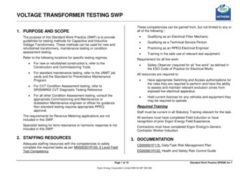
Medium Voltage Transformers (General Information)DescriptionCore ConstructionFederal Pacific medium voltage transformers are availablein a wide variety of types and ratings to provide reliable andversatile electrical distribution.The transformer cores are made of high grade siliconelectrical steel laminations with high magnetic permeability.Precision steel cutting machines are used to precisely cutthe steel laminations to be free of burrs.Medium voltage dry-type transformers for use in the UnitedStates must comply with the efficiency levels as set forthin the Code of Federal Regulations Title 10 Part 431.196 (10CFR 431.196) as published by the US Department of Energy.The changing needs and variable load densities of industrialand commercial power systems create the need to locatetransformers close to the electrical center of the load —providing flexibility for change and economical distributionof power.Federal Pacific dry-type transformers are ideally suited forthese applications. The ventilated air-cooled constructioneliminates the concern for contamination and toxicity ofcooling liquids. They do not require the expensive vaults,fluid leakage containment provisions, or fire protectionsystems needed for liquid filled units to satisfy NationalElectric Code requirements.Laminations are hand stacked to computer generatedspecifications to assure correct positioning for close fittingjoints to minimize noise and core loss. Each lamination hasan insulating coating bonded to both sides to minimizeeddy-current losses.The core legs are arranged in a “stepped” configuration toaccommodate the coils and to provide maximum cooling andstrength. The completed core assembly is rigidly clampedwith steel members to prevent movement and to providesupport for the coils.Lower installed costs and minimum maintenancerequirements make Federal Pacific dry-type transformersan ideal choice for new or existing installations.Transformers are available in three-phase ratings from 15kVA to 10,000 kVA and single-phase from 15 kVA to 3,000kVA. All standard primary and secondary voltage ratingsare provided to match load requirements to the distributionsystem.Units can be arranged for standard direct connection to highvoltage and low voltage distribution protective equipmentor provided as stand-alone transformers.Medium Voltage Industry StandardsFederal Pacific medium voltage transformers are designedand tested in accordance with the following standards: IEEE C57.12.01 General Requirements for Distribution,Power and Regulating Transformers. IEEE C57.12.91 Standard Test Code for Dry-Type Distributionand Power Transformers.Additionally, Federal Pacific can provide transformersmeeting applicable CSA, IEC, and ABS standards.Step-Lap Miter Core ConstructionCoil ConstructionCoils are precision wound in a circular or wound configuration(depending on design requirements) using aluminumconductor material as standard. Copper conductors canalso be provided as an option.Federal Pacific typically employs sheet-wound secondarywindings. The windings are separated by insulation layersand spacers. These sheet windings offer the advantage ofvirtually eliminating axial short circuit stresses. Nomex insulated wire-wound primary windings are placed directlyover the secondary windings with an insulating barrierbetween the coils consisting of spacers and sheet insulationapplied to the proper thickness. Primary windings may belayer-wound or disc-wound depending upon the designrequirements. All coils are properly braced to withstandfull short circuit forces.7
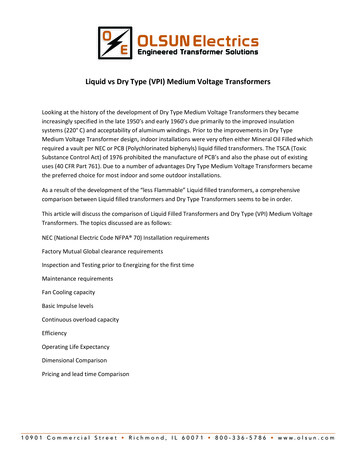
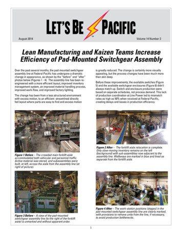
Medium Voltage Transformers (General Information)AssemblyThe completed coil units are placed on the core legs.Top core yokes are put into place and securely clamped.Electrical connections are made using welded aluminumor brazed copper, to ensure reliable service.After installation of the mounting hardware, the completecore and coil assembly is submersed and impregnated withan insulating varnish. The assembly is completely coated toprotect the unit from dust and moisture as well as providehigh dielectric strength. After dipping, the varnish is fullycured in a drying oven.Completed core and coil assemblies receive a finalinspection and testing prior to installation in the enclosure.When installed, vibration isolation pads are provided toisolate the core and coil assembly from the base structure.All structural parts are grounded to prevent induced voltagebuildup.TapsPrimary windings are furnished with full capacity tapconnections to provide adjustment to accommodatevariations in the incoming high voltage. All units include, asstandard, two (2) 2-1/2% taps full capacity above nominal(FCAN) and two (2) 2-1/2% taps full capacity below nominal(FCBN).The tap connections are located on the front side of eachcoil. Taps are accessible behind removable covers and caneasily be changed by moving jumpers between connectionpoints when the transformer is de-energized.Federal Pacific can accommodate most customer-specifiedtap arrangements.TerminalsWiring compartments located behind removable coverswith terminals are arranged to accept cable connectors.A flexible grounding strap is provided to connect the coreand coil assembly and enclosure to a ground stud or pad.Optional TestingIn addition to the standard testing summarized on page 5,Federal Pacific can complete the following testing on allmedium voltage transformers. Additional charges may apply.Partial Discharge (PD) - tests for harmful levels of PD thatwould destroy insulation over time. Refer to the Glossaryfor further definition.Impulse Testing - tests the transformers ability to withstandovervoltage transients from lightning or switching. Theimpulse rating for a transformer is known as the basiclightning impulse level (BIL). This test exposes thetransformer to simulated impulse waves in the laboratorysimilar to those experienced in the field.– Full Impulse Testing - Consists of applying (4) impulsewaves to the transformer, a reduced impulse, (2)chopped and a full wave test.– QC Impulse Testing - Consists of applying (1) reducedand (1) full impulse wave to the transformer.Federal Pacific Medium Voltage Unit Substation Styletransformer designed for close coupling on the primary (highvoltage) side.8Completed Core and Coil assembly shownwith optional fan cooling
High Voltage General Purpose TransformersGeneral InformationFederal Pacific’s High Voltage General Purpose (HVGP)transformers are freestanding indoor general purposedistribution transformers. HVGP style transformers can benecessary where there are special space requirementsand equipment configurations. Primary voltage ratings are2.4—15 kV and secondary voltages are less than 600 V.These transformers are highly efficient meeting U.S. DOE 10CFR-431 (2016) minimum efficiency requirements. Standardefficiency models for export use only are also available.Since these transformers are made to order, optional 80 Cand 115 C temperature rises are also available.To indicate the HVGP transformer required replace “XX”with the primary and secondary voltages from the VoltageCodes table below.For instance, catalog number GTM4112H is an HVGP styletransformer rated 13800 Delta—208Y/120.Style ATable I (2.4KV and 5KV Class)KVA15304575Catalog NumberGT(XX) S15HGT(XX) S30HGT(XX) S45HGT(XX) S75HEnclosureAAAATable II (7.2 KV, 8.6KV, and 15 KV Class)KVA112.5150Catalog NumberGT(XX) S112.5HGT(XX) S150HEnclosureBB225GT(XX) S225HB300GT(XX) S300HB500GT(XX) S500HB750GT(XX) S750HB1000*GT(XX) S1000HB1500*GT(XX) S1500HB* Dimensions shown on page 12 are 480V secondary only.Style BVoltage Codes2400 Delta4800 DeltaPrimaryAC4160 Delta7200 DeltaBD8320 DeltaG12000 DeltaJK13200 DeltaMSecondary2480 Delta4480Y/277L12470 Delta13800 Delta240 Delta208Y/120359
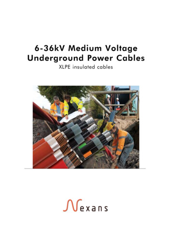
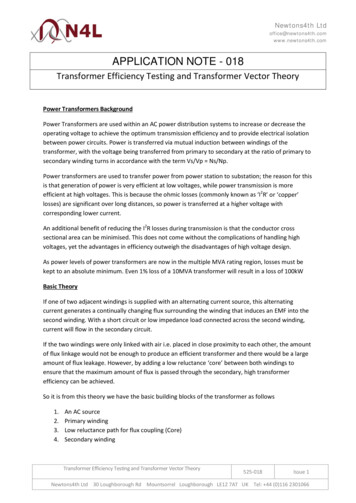
High Voltage General Purpose TransformersDimensional DataHVGP Approximate Dimensions and Weights - Indoor Only (DOE 2016 Efficiency Compliant)Three Phase — 150 C Rise — 2.4 kV and 5 kVBC5/16" DIA. HOLE7/16" DIA. HOLEFIGURE 1FIGURE 2REMOVABLEPANELSTAPSIDEHAE9/16" DIA. HOLEEHANDLEFDG(4) 5/8" DIA. MOUNTING HOLESNet Wt.in Lbs.540625725965153045751-1/2PRIMARYTERMINALSStyle AKVASECONDARYTERMINALSENTRANCE AREA(BOTH ENDS)FIGURE .7516.7519.757777.5Fig. 1Fig. 1Fig. 1Fig. 1Fig. 1Fig. 1Fig. 2Fig. 2B7/16" DIA. HOLECHANDLEREMOVABLEPANELSTAPSIDE10"ENTRANCE AREA(BOTH ENDS)1 3/4FF10"HSECONDARYTERMINALSJDFIGURE 4GPRIMARYTERMINALS4" BASE3/4A9/16" DIA. HOLEKEJACKING, TOWING, ANDLIFTING PROVISIONS1 3/4(4) 5/8" DIA. MOUNTING HOLES3/4 BOTTOM ENTRANCE AREA(CENTERED FROM TO BACK, SIDE TO SIDE)Style BKVA112.51502253005007501000*1500*Net Wt.in Lbs.165017782250253034285400630083001 3/4FIGURE 54.254.254.2530303030303030303939393939393939Fig. 4Fig. 4Fig. 4Fig. 4Fig. 4Fig. 4Fig. 4Fig. 4Fig. 5Fig. 5Fig. 5Fig. 5Fig. 5Fig. 5Fig. 5Fig. 5* Dimensions shown are for 480 secondary only. Consult factory for other voltages.10
High Voltage General Purpose TransformersDimensional DataHVGP Approximate Dimensions and Weights - Indoor Only (DOE 2016 Efficiency Compliant)Three Phase — 150 C Rise — 7.2 kV, 8.6 kV & 15 kVFIGURE 11-3/4"FIGURE 23/4"1-3/4"Notes:1-3/4"1. Covers and all panels are removable2. Grounding block (welded to base)(2) 1/2 - 13 tapped holes(2) 7/16" Dia.3. Lift eyes are a welded integral part of the base(4) 9/16" Dia.Terminal Material: Tin Plated AluminumTerminal Spade 500—Style BB480V1111112227.2kV, 8.6kV, DEENTRANCE AREA(TYPICAL BOTH ENDS)PRIMARYTERMINALS4" BASESEE NOTE 2(TYPICAL BOTH SIDES)EVIBRATIONISOLATORSJACKING, TOWING ANDLIFTING PROVISIONS(4) 5/8" MOUNTING HOLESKVA112.5150225300500750Net Wt.in 16.5444444* Refer to Unit Substation Style Transformers for larger KVA ratings.11
Unit Substation Style (USST) TransformersDescriptionFederal Pacific specializes in the design and manufactureof medium voltage unit substation style transformers.A unit substation consists of one or more transformersclose-coupled to one or more switchgear or switchboardassemblies.A unit substation is considered a secondary unit substationwhen the output voltage is less than 1000 volts.Unit substations bring power closer to the load providingreduced power losses, better voltage regulation, improvedservice continuity, improved functional flexibility, lowerinstallation cost and more efficient space utilization.ArrangementsFederal Pacific unit substation transformers meet a widevariety of application requirements with the highest degreeof service reliability.A Federal Pacific substation is a coordinated, engineeredelectrical center designed to safely step down distributionvoltage to utilization voltage. It usually supplies secondaryvoltages ranging from 208Y/120 to 600 volts and primaryvoltages of 2400 to 13800 volts.It typically provides power to industrial plants, officebuildings, commercial buildings, public buildings, hospitalsand schools. The form, rating, and characteristics ofunit substations and their transformers are determinedby the design of the electrical distribution system andthe requirements of the particular loads and installationconditions.Incoming Line Air Interrupter SwitchFederal Pacific’s Type Auto-jet II air interrupter switch-twoposition (open-close), three-pole with manually-operated,stored-energy mechanism provides quick-make, quickbreak operation for disconnecting the transformer incomingline. Federal Pacific can also easily accommodate the busarrangements of other high voltage switch vendors. Theswitch compartment is bolted directly to the high voltageside of the transformer.Incoming Line Terminal CompartmentWhen a disconnect or overcurrent device is not requiredas an integral part of the lineup, an air-filled terminalcompartment (ATC) is bolted directly to the high voltageend of the transformer section. The metal-enclosed ATCterminal compartment matches the height and depth of thetransformer section and is provided with bolt-on end panelsfor accessibility to terminal connections. The compartmentcan be arranged for single or loop feed with potheadsor clamp-type terminals for either top or bottom cableentrance. Lightning arresters can be supplied when requiredfor protection against voltage surges. Another incomingtermination option is the “Non-Segregated Air TerminalChamber” having no separating steel barrier and is utilizedto minimize the over-all width of the unit substation by asmuch as 3 feet. It also eliminates the need for expensiveflex bus.12Low Voltage Distribution SectionsA complete selection of distribution and protective equipmentis available to meet application requirements. Unit substationtransformers from Federal Pacific can be arranged for directconnection to a variety of equipment including low voltagedrawout switchgear, distribution switchboards, group mountedpower panelboards and motor control centers.For those applications where secondary distribution equipmentis not required, an outgoing air-filled terminal compartment(ATC) can be provided for top or bottom cable entrance.The compartment bolts directly to the transformer and hasremovable end panels for accessibility. Provisions can alsobe made to accommodate busway. Non-segregated ATC’s asdescribed for the incoming compartment are likewise availablefor the low voltage outgoing section.Features of Typical USST Transformers1. Round cylindrical coils assure proper ventilation and providemechanical strength for fault stresses. The units are eitherbarrel wound or disc wound (depending on voltage) usingaluminum conductor with insulated coil supports.2. Core structures are fabricated in a “stepped” configurationfrom special high-grade, cold rolled, silicon steel. The steellaminations are clamped at the top and bottom to absorbvertical stresses on the core.3. 220 C insulation systems using Nomex paper and resin glasslaminates provides long operating life and quiet operation.The complete core and coil assembly is impregnated withpolyester varnish and oven cured to make the assemblyhighly resistant to moisture.4. High dielectric interphase barriers assure positive phase tophase insulating characteristics.5. High voltage tap connections are easily accessible byremoval of front panels. The centrally located taps arechanged by moving jumpers between connection pointswhen the transformer is de-energized.6. Rugged enclosure base with provisions for lifting, jacking,towing, skidding or rolling for installation.7. Rigidly braced low voltage bus bars arranged for properelectrical connections to the transformer. The low voltagebus is equipped with flexible connectors to the core andcoil assembly to reduce transmission of vibration to theconnected equipment.8. Diagrammatic nameplate provides complete rating andconnection information.9. Vibration isolation pads isolate core and coil assembly fromthe base structure to reduce sound levels.10. Optional fan cooling equipment to provide additionaltemporary overload capacity of 33-1/3% kVA capacity forunits with self-cooled ratings of 300 kVA and above.Future Forced Air Cooling (FFA) provisions are also availableand include sufficient current-carrying capacity on internalbus bars. Fans and controls can be installed at the factoryor can be shipped for installation at the jobsite.
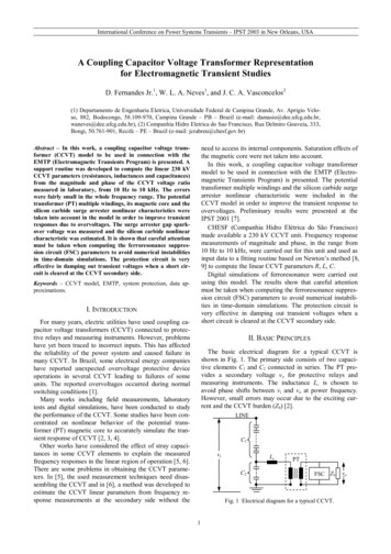
Unit Substation Style (USST) TransformersOptions and AccessoriesDigital Temperature Monitors are used for more intelligentinteractive transformer temperature monitoring for safety relayschemes and SCADA options.Dust Filters are placed over ventilation openings to provide adegree of protection from dust accumulation on the inside ofthe transformer enclosure.Electrostatic Shielding is commonly used in areas wheresensitive electronic equipment is being fed by the transformer.The electrostatic shield provides another level of isolationbetween the primary and secondary windings to reducecommon mode noise and harmful transients.Flexible Connectors are used to simplify the connectionswhen close-coupling to equipment on the secondary side ofthe transformer.Hinged Doors are an option for indoor transformers allowingeasy access to the core and coil of the transformers. Standardenclosures are made up of bolted panels.IR Viewing Windows are used to allow for monitoring thetemperature of a transformer’s internal parts without havingto de-energize and remove transformer panels.RC Snubbers protect dry-type transformers from highfrequency, high voltage transients due to switching of nearbyvacuum or SF6 breakers. These voltage transients cannot beprevented by traditional surge arresters. RC Snubbers haveproven to provide reliable protection from these fast transients.Rodent Screening is a fine metal mesh often installed overthe ventilation openings of dry-type transformers to preventdamage from rodents or other small animals.Space Heaters are used to keep transformer dry duringlong-term storage or for pre-drying the transformer beforeenergizing.Surge/Lightning Arresters serve to protect transformersfrom high transient voltages primarily caused by lightning orswitching. Distribution, Intermediate and Station Class optionsare available. Distribution arresters are the most frequentlyused for dry-type transformers. Intermediate arresters formedium-duty applications provide improved protection andhigher energy handling capability. Station class arresters forheavy duty applications have the highest degree of protectionThermostats installed within the coils protect the transformerfrom overheating by triggering system alarms and actions toshut down the unit when necessary.A Federal Pacific unit substation transformer with a Federal Pacific close coupled line interrupting switch.13
Unit Substation Style (USST) TransformersOptions and AccessoriesEnclosure - The standard configuration for Federal Pacificunit substation transformer enclosures is Category “C”i
Sealed transformer Special impedance transformer Testing transformer Transformer of 20% or more tap range Uninterruptible power supply transformer Welding transformer Rebuilt or refurbished transformers 50 Hz transformers1 Formal definitions for each of these types of