Transcription
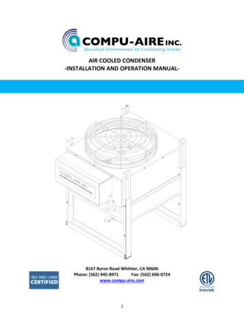
AIR COOLED CONDENSER-INSTALLATION AND OPERATION MANUAL-8167 Byron Road Whittier, CA 90606Phone: (562) 945-8971Fax: (562) 696-0724www.compu-aire.com1
TABLE OF CONTENTS1GENERAL SAFETY INFORMATION . 42CONTACTING COMPU-AIRE FOR TECHNICAL ASSISTANCE . 83RECEIPT OF UNIT AND TRANSPORTATION. 9TRANSPORTATION MODE .9IMPORTANT – READ BEFORE INSTALLING.104LOCATING THE CONDENSER . 104.1Connections .124.2Structural Support .124.3Electrical Support .124.4Refrigeration Piping .124.5Electrical Connection.155GENERAL WIRING DIAGRAM . 176COMPONENTS OPERATION GUIDE AND MAINTENANCE . 187UNIT DIMENSIONS AND GENERAL COMPONENT LAYOUT. 198COMPONENTS IDENTIFICATION . 229START-UP . 2310LOW AMBIENT CONTROL OPTIONS: . 2310.1Fan Speed Control (Low ambient control up to -20 F) .2310.2Head Pressure Control Valve (Low ambient control below -30 F) .2411TECHNICAL DATA . 2612GENERAL MAINTENANCE. 2713PART LIST . 28FIGURESFigure 1 Transportation . 9Figure 2 Recommended Minimum Distance Requirement . 11Figure 3 2 to 28 Ton Air Cooled Condenser Leg Dimension. 11Figure 4 Typical Piping Schematic . 14Figure 5 Typical Wiring Diagram 11 TO 19 Ton . 17Figure 6 Unit Dimension 2 TO 5 Ton Unit Shown . 19Figure 7 Unit Dimensions 6 to 9 Ton Unit Shown . 202
Figure 8 Unit Dimension 11 to 19 Ton Unit Shown . 21Figure 9 Front Layout-Single Fan . 22Figure 10 Liquid Receiver Option . 25TABLESTable 1 Refrigeration Line Size . 13Table 2 Control Panel Layout . 22Table 3. Part List . 283
1 GENERAL SAFETY INFORMATIONPLEASE CAREFULLY READ THE FOLLOWING SAFETY INFORMATION BEFORE PROCEEDINGFURTHERThis installation and operation manual (IOM) contains important safety information that should befollowed during installation or servicing of a Compu-Aire Air Cooled Condenser system. Below isgeneral safety information as well as descriptions of safety and accident prevention symbols thatwill be utilized throughout this document. In addition to safety information provided by this manual,all warnings, cautions, and safety instructions located on the unit should be adhered to at all times.If applicable, local codes or ordinances and any other safety requirements must also be taken intoconsideration when installing or servicing the unit.This IOM should be stored in a safe and accessible location for service personnel during installationor servicing operations. When no longer needed, this IOM should be returned to its original locationfor future reference.4
DESCRIPTION OF IMPORTANT ACCIDENT PREVENTION SAFETY SYMBOLSDEFINITION1SYMBOLIndicates an extremely hazardous situationwhich, if not avoided, will result in death orserious injury. Use of this symbol is limited to themost extreme situationsIndicates a potentially hazardous situation which,if not avoided, could result in death or seriousinjury.Indicates a potentially hazardous situation which,if not avoided, may result in minor or moderateinjury. Caution may be also be used to alertagainst unsafe practicesIndicates a statement of company policy as themessage relates directly or indirectly to the safetyof personnel or protection of property1Accident prevention definitions per ANSI Z535.2- 2011.HIGH VOLTAGE!5
Unit utilizes high voltage power supply. There is a high risk of arc flash and electric shock. Alwaysproceed with caution and wear protective equipment per NFPA 70E specifications at all timesbefore working on the electrical control panel. Failure to comply can cause serious injury ordeath. The required unit power supply can be found on the nameplate located on the unit.Service personnel should ensure that the main power supply to the unit is disconnected and lockedout from the feeder when installation or servicing operations are being performed and when poweris not needed.Compu-Aire air cooled condenser equipment requires a permanent power connection from anisolated circuit breaker. The customer must provide earth ground to the unit per NEC, CEC, andlocal codes when applicable.INSTALLATION AND SERVICING PERSONNEL TRAINING & QUALIFICATIONS REQUIREMENTSInstallation and service of this equipment should be done only by qualified personnel who havebeen specially trained and qualified in the installation or servicing of HVAC equipment. Improperinstallation may result in unaccountable loss or damage.EQUIPMENT TRANSPORTATION, PROPER BRACING, & HIGH-SPEED MOVING PARTSEvery precaution should be taken before the time of transportation of the equipment that alltransportation equipment such as forklifts is properly rated to transport the equipment. Not doingso may cause equipment damage, injury, or death. Please refer to the shipping slip or contact thefactory to determine the weight of the unit.Once installation of the equipment is complete, the equipment should also be properly braced oranchored to the floor or wall if necessitated by local codes and ordinances.High-speed moving parts can cause serious injury or death. Ensure that all unit panels and guardsare installed before any functional testing is done.SHARP EDGES, SPLINTERS, EXPOSED FASTENERS, AND HOT SURFACESWhile every precaution has been made to ensure sharp edges, splinters, and exposed fasteners havebeen minimized internally and externally on the unit to prevent personal injury, it is highly6
recommended that all personnel installing or servicing the unit wear safety headgear, glasses,gloves, and shoes at all times. In addition, precaution should be taken to ensure the unit issufficiently cool to perform any type of servicing operations.A first aid kit should be readily available and accessible at all times when needed.EQUIPMENT STORAGE POSITION AND LOCATIONImproper storage of unit may cause unintentional damage. If possible, keep unit in the uprightposition and stored in the unit original shipping package. In addition, steps should be taken toensure that the unit is protected damage.EQUIPMENT TRANSPORTATIONPrior to transporting unit to final installation location, ensure that there are no risks of overheadinterference. Relevant measurements of the unit and all doorways should be taken to determine ifunit will be able to be transported to its final location without causing damage to the building and tothe unit itself. Required unit clearances at installation site should also be confirmed prior to unittransportation for safe and proper installation operations.7
2 CONTACTING COMPU-AIRE FOR TECHNICAL ASSISTANCECompu-Aire uses the latest in electronic and software technologies to develop some of the mostreliable and cost efficient air conditioning systems in the world. Since many of our customerinstallations are sensitive to down time, we stock nearly all components for your system ready forsame day shipment. In addition, our service department can usually diagnose and repair theelectronic components and return them to you within a few days.Our customer support staff is available should you require assistance in diagnosing a problem or insetting up your air conditioning system. During usual business hour, you may call at (562) 945-8971between 8:00am and 04:30pm, Pacific Time, Monday through Friday except holidays, or you maysend a facsimile message at (562) 696-0724 anytime. Finally, you may write us at Compu-Aire, 8167Byron Road, Whittier, CA 90606.Please do not return system components without prior authorization from Compu-Aire. Whetherrepair or replacement is required for in warranty or out of warranty parts, Compu-Aire must knowwhat is being returned to keep proper records of returned parts. Call Compu-Aire’s service centerfor a returned merchandise authorization number (RMA) and clearly mark all packages on theoutside with the number before sending them to us.When contacting the factory, please have information ready as to the model and size of the airconditioner system and most important, the job number. Compu-Aire keeps a file on all equipmentsold detailing system components using this latter number. All such information can be found onthe Warranty Plate attached to each unit.8
3 RECEIPT OF UNIT AND TRANSPORTATIONUpon receipt of the unit, a visual inspection is required. The unit packaging should be entirely intactand the crate should not be damaged. If any damage is found, make note of the damage on theshipping bill of landing prior to signing. Transport the unit to the desired location in the uprightposition to avoid damaging to any external panels or internal components. Once the unit isuncrated and in the desired location, inspection of the unit for any external damage is crucial as thismay be indicative of internal damage. Any signs of damage to the packaging or system panels orincomplete shipments require a claim to be filed with the shipping company. Freight damage claimsare the responsibility of the receiver.Any items designated as field installed shall be packaged inside of the unit and must be removedand installed prior to startup of the equipment.Optional articles such as jack-stand parts, condensate pump, and remote control panel are packagedseparately.REPORT ANY DAMAGE TO THE CARRIER. COMPU-AIRE IS NOT RESPONSIBLE FOR FILING OF ANYCLAIMS. ALL NEEDED INSPECTION AND CLAIM FILING IS THE RESPONSIBILITY OF THE RECEIVERFigure 1 TransportationTRANSPORTATION MODEVisual inspection of the outer casing provides a simple indication of possible internal damage to theequipment. Move the unit to the installation site in the upright position.FILE A CLAIM WITH THE SHIPPING COMPANY IF THE SHIPMENT IS DAMAGED OR INCOMPLETE.FREIGHT DAMAGE CLAIMS ARE THE RESPONSIBILITY OF THE RECEIVER.9
Each fan section has heavy leg supports with lifting holes at the top. Do not lift with a chokesling around the unit. Spreader bars are recommended for lifting multiple fan units . Under nocircumstances should the coil headers or piping be used for moving or lifting the condenserLeg assembly: The legs must be unbolted from the shipping position and extended prior toplacing the unit on its pad. Each leg extends down approximately 18 inches and reattachesusing same bolt (see figure 3).IMPORTANT – READ BEFORE INSTALLINGCheck the power supply. Voltage, frequency and phase must correspond to that specified on theunit nameplate. The power supply must be able to handle the additional load imposed by thisequipment.4 LOCATING THE CONDENSERConsult local building codes and National Code for special installation requirements. The remoteheat exchangers must be located in an area that will ensure maximum security; maintenanceaccessibility and free air flow into and out of the unit. The unit should not be placed closerthan 48 inches from any wall or other obstruction. When two or more units are installed inthe same area, space them apart by a minimum of 96 inches. Short-circuiting of the airflowor the intake of warmer air from another unit will seriously degrade the performance of theair-cooled condenser.Structural supports and roof or platforms should be sufficiently strong to support thecondensers operating weight. For roof installations, mount the condensers on steel supportsin accordance with local codes. For ground installations, a concrete pad is sufficient to carrythe load.Noise consideration should also be considered when locating an air-cooled condenser. Proximity towindows, walls, and surrounding structures can cause objections by the occupants.When installing the unit, allow sufficient space for air flow clearance, wiring and servicing the unit.For multiple units, place them as far apart from each other as possible for optimum air circulation.The location of the unit should be selected based on air circulation in the room and service accessrequirement. Proper clearance is important for the unit function and access to various componentsfor service.10
MINIMUM DISTANCE REQUIREMENT.IF USED, 80% MIN. FREE OPENING AREA OF LOUVER ISRECOMMENDED. WALL OR FENCE HEIGHT MAY NOTEXCEED TOP OF UNIT.WALLFigure 2 Recommended Minimum Distance RequirementFigure 3 - 2 to 28 Ton Air Cooled Condenser Leg Dimension11
4.1 ConnectionsIn connecting the unit, several items must be addressed. They are:4.1.1Structural SupportThe unit can be installed directly on concrete pads or on the steel supports in accordance to localcodes. The floor should be level. Gasket material should be placed between the leg support of theunit and the floor to act as vibration isolator.4.1.2Electrical SupportA fused disconnects or a HVAC approved circuit breaker must be field provided and install per theNational Electric Code (NEC). There is access to the unit for electrical connection through the unitelectrical box. Be sure unit is properly grounded.4.1.3Refrigeration PipingIt is of the greatest importance that all refrigerant piping be cleaned and free from dirt and moisture.One drop of water in a refrigerant system will greatly deter the operation and efficiency of the system.Upon installation, all open ends of piping should be sealed to prevent condensation from accumulatinginside. (If it is not to be completed during the day). This avoids future problems, malfunctions andcorrosion.It is suggested that hot gas and liquid return lines be silver soldered, using one of the many types, suchas silfoss, etc. Absolutely avoid soft solders such as 50/50 or 95/5. Use a flow of dry nitrogen throughthe piping while being soldered. (To eliminate formation of a copper oxide scale on the inside of thepiping).SUGGGESTED REFRIGERANT PIPE SIZE“QUICK RULE OF THUMB”TONS23457½1012 ½1315DISTANCE BETWEEN INDOOR UNIT AND AIR COOLED /8"1-5/8"1-5/8"
NOTES:1. Distances shown are one way. Pipe sizes are based on Total Equivalent Length (TEL).Verify sizes with ASHRAE Standards.2. Compu-Aire will not be responsible for any errors in pipe sizing or improper running of thepiping.It is highly recommended that sound engineering practices be used for routing, piping, "p"traps,double risers and insulator requirements.3. LIQ. LIQUIDDIS. DISCHARGE4. All sizes are copper O.D.5. Provide isolation valves for piping lines outside any air conditioner unit.Table 1 Refrigeration Line Size13
Figure 4 Typical Piping Schematic14ELANLPCSHUT OFF VALVEFIELD PROVIDEDFACTORY MOUNTEDSCHRAEDER VALVESEE DETAIL A FORINVERTED 'P' TRAPAND DETAIL 'B' FORANBIENT STATHOT GAS LINE 1COMPU-AIRE UNITDETAIL ALIQID LINE 1OTRONGROUNDPOWER INPUTCONTECTORDETAIL BNATIONAL ELECTRICAL CODE/LOCAL APPLICABLE CODE2- ALL PIPING MUST BE PER ASHRAE STANDARDNOTES:1- COMPLY WITH ALL APPLICABLE PORTION OFFIELD PIPINGSINGLE CIRCUIT (1 THRU 5 TON)DOUBLE CIRCUIT (6 THRU 30 TON)LIQUID LINEHOT GAS LINEAIR INAIR COOLED CONDENSERAIR OUTCONDENSERCOILAMBIENT STAT CONTROLTRANSFORMERAIR OUTFIELD MOUNTEDRUBBER INSULATEDSTEEL CLAMPCONTROLPANELCONTROLVARIABLE SPEEDAMBIENT STAT PROTECTEDWITH SUN SHIELDREQUIRES IN MULTIPLE FAN UNITLEAD FAN DOES NOT REQUIRES
Standard units are designed for ambient controls down to 0 F. Air cooled condensers are provided withvariable speed fan motor for ambient temperature between -20 F to 115 F.Condensers are dropped shipped from another source. Control panels for the condenser are shippedwith the air conditioners. This control panel is to be wired and connected in the field. Provide a raintight fused disconnect switch. Single fan units are generally single phase.The power supply to the air cooled condenser must be brought through a fused disconnect that isproperly sized for electrical requirement of the condenser.Two 28 gauge wires are required between the air conditioner and the condenser to interlock indoor unitwith the outdoor unit. Run wires in conduit. The connection is 24 VAC.Suggested pipe sizes are: Refer to the ASHRAE guide for proper sizing and layout. A CHECK VALVE MUSTBE INSTALLED IN THE DISCHARGE LINE.FOR UNITS REQUIRED AMBIENT BELOW 70 F.An optional head pressure control is provided. Refer to low ambient section of this manual.Suggested pipe sizes are:Hot gas – 7/8” – 50 ft TELLiquid Drain – 1 1/8” – 50 ft TEL (refer to ASHRAE guide for details)(Liquids drain should be sized based on 100 FPM velocity) Once it is ascertained as to what kind of low ambient the unit is provided with, install propersize pipes and evacuate using triple evacuation method.Charge units based on superheat, set superheat not lower than 10 F and not greater than 15 F.Units provided with head pressure control valve and ambient below -10 F will require additionalcharge.Check valve-provide a check valve for the discharge like at the air cooled condenser.4.2 Electrical ConnectionThe unit is completely factory wired with self-contained controls.IMPORTANT - Before proceeding with the electrical connections, make certain that the volts, hertzand phase correspond to that specified on the unit rating plate. Also, check to be sure that serviceprovided by the utility is sufficient to handle the additional load imposed by this equipment. Refer tothe unit rating plate for equipment electrical requirements. The attached wiring diagram shows theproper high and low voltage field wiring.Make all electrical connections in accordance with National Electrical Code and any local codeordinances that may apply. USE COPPER CONDUCTORS ONLY.15
WARNING -- The unit cabinet must have an uninterrupted or unbroken electrical ground to minimizepersonal injury if an electrical fault should occur. It is important that an electrical ground wire ofadequate size can be connected to the ground lug provided inside the control box.Supply voltage at the unit must be within 10% of the voltage indicated on the nameplate for a dual voltagerating, supply voltage must be within 5% from the lower nameplate rating and within 10% from the higherrating. Phase to phase imbalance must not exceed 3%. Contact your local utility company for correction ofimproper line voltage. Improper electrical power supply may cause premature failures and void unitwarranties16
Figure 5 Typical Wiring Diagram 11 TO 19 Ton17L1 L2 L3POWER SUPPLY208-/460V/3Ph/60HzOR 380V/3Ph/50HzUSE COPPERCONDUCTOR ONLYPOWERBLOCKCONTACTORBLOCK(TYP.)FUSED DISCONNECTFIELD PROVIDED( BY OTHERS )GROUNDFAN 2CONTROLTRANSFORMER(SECONDARY 24V)CIRCUITBREAKER(BUILT IN )TO COMPU-AIRE UNITTERMINAL 9 & 10 FOR SYSTEM 2100ON TB #1TERMINALBLOCK(IF USED)LIMIT CONTROL SW. # 1VRED24VACM1L2* TRANSDUCERSCPWHTP1BLKL15 GENERAL WIRING DIAGRAM
6COMPONENTS OPERATION GUIDE AND MAINTENANCEHIGH-SPEED MOVING PARTSRisk of high-speed moving parts can cause injury or death. Disconnect all local and remote electricpower supplies and make sure fans have stopped rotating before performing service operations.The unit you have received is very special. It is specifically designed for Computer Roomapplications. Please read the following INSTRUCTIONS prior to working on the equipment.ELECTRICAL DATA: 208v, 3 phase, 60 h, 460v, 3 phase, 60 hz, 208v, 1 phase, 60 hz, 575v, 3 phase, 60hz, 3 phase, 60 hz, or 415/380v, 3 phase, 50 hz.Please check the voltage.NAMEPLATE DATA: Refer to the unit name plate. It indicates all the electrical data for the unit.LOCAL ELECTRICAL CODES OR ANY OTHER APPLICABLE CODES MUST BE COMPLIED WITH PRIOR TOWORKING IN THE UNIT.ELECTRICAL PANELThe electric panel should be inspected for any loose electrical connections.AIR COOLED CONDENSERS (ACC): is mostly dropped shipped to the job site ahead of the unit. Aircooled condenser supplied are usually provided with one of these options:A. Fan CyclingB. Variable Speed Fan MotorC. Head Pressure ControlD. Control Box where motor wires terminates less any controlsE. Access fittings to hook up SCR controllerCONTROL PANEL: This is for the air cooled condenser which is shipped from COMPU-AIRE with the airconditioner. This control panel is to be installed and wired in the field.FOR UNITS EQUIPPED WITH LOW AMBIEANT CONTROL BELOW -30 F: A head pressure control valve foreach refrigeration circuit is provided and is shipped with the Computer Room air Conditioner for a FIELDinstallation on the air cooled condenser. An appropriate control panel for with fan cycling control is alsosupplied for field installation on the air cooled condenser.ALL REFRIGERATION PIPING SHALL BE INSTALLED PER ASHRAE STANDARDS.18
Figure 6 Unit Dimension 2 TO 5 Ton Unit Shown1930-3/4"(781mm)FRONTVIEWTOPVIEWLIQUID LINEDISCHARGELINE1.06"(27mm) (TYP.)18-1/4"(464mm)ELECTRICALCONTROLPANEL(HINGED DOOR)30-1/2" 33-1/2"(775mm) (850mm)AØ5/8"(16mm) (TYP.)MOUNTINGHOLESCONDENSERFOOTPRINT DIMENSIONSSECTION A-AA10"(305mm)42-1/2"(1080mm)32-7/8"(835mm)OUTER TELESCOPIC LEGRETURN BEND(RETURN BEND COVER NOT SHOWN)INNER TELESCOPIC LEGLIFTING HOLES1-1/2"ISOMETRIC(38mm)VIEWFAN GUARDNOTES:1. LOW AMBIENT CONTROL OPTIONS INCLUDE FAN CYCLING, VARIABLEFAN SPEED OR HEAD PRESSURE VALVE CONTROL2. NON-FUSED OR LOCKING DISCONNECT SWITCH PROVIDE AS ANOPTION3. TELESCOPIC LEGS ARE FACTORY PROVIDED AT REDUCED HEIGHT ANDARE TO BE EXTENDED IN THE FIELD BY OTHERS FOR PROPER UNITOPERATION4. P-TRAPS AND SHUTOFF VALVES ARE TO BE PROVIDED AND INSTALLEDBY OTHERS5. RECONMENDED SIDE CLEARANCE IS 48" (1219 MM)INTAKEAIRSIDEVIEW7.00"(178mm) EXHAUSTAIR7UNIT DIMENSIONS AND GENERAL COMPONENT LAYOUT
Figure 7 Unit Dimensions 6 to 9 Ton Unit Shown2048-1/4"(1226mm)MOUNTING HOLESFRONTVIEWTOPVIEWØ5/8"(16mm) (TYP.)MOUNTINGCONDENSERHOLES FOOTPRINT DIMENSIONSSECTION "(1283mm)LIQUID LINEDISCHARGELINE30-1/2"33-1/2"(775mm) (850mm)1-1/8"(29mm) (TYP.)A18-1/4"(464mm)ELECTRICALCONTROLPANEL(HINGED DOOR)EXHAUSTAIROUTER TELESCOPIC LEGRETURN BEND(RETURN BEND COVER NOT SHOWN)INNER TELESCOPIC LEGISOMETRICVIEWLIFTING HOLESØ1-1/2"(38mm) (TYP.)NOTES:1. LOW AMBIENT CONTROL OPTIONS INCLUDE FAN CYCLING, VARIABLEFAN SPEED OR HEAD PRESSURE VALVE CONTROL2. NON-FUSED OR LOCKING DISCONNECT SWITCH PROVIDE AS ANOPTION3. TELESCOPIC LEGS ARE FACTORY PROVIDED AT REDUCED HEIGHT ANDARE TO BE EXTENDED IN THE FIELD BY OTHERS FOR PROPER UNITOPERATION4. P-TRAPS AND SHUTOFF VALVES ARE TO BE PROVIDED AND INSTALLEDBY OTHERS5. RECONMENDED SIDE CLEARANCE IS 48" (1219 MM)7"(178mm)FAN GUARD
Figure 8 Unit Dimension 11 to 19 Ton Unit Shown21Ø5/8"(16mm) (TYP.)MOUNTINGHOLESSECTION A-ACONDENSERFOOTPRINT DIMENSIONS48-1/4"(1226mm)MOUNTING HOLESFRONTVIEWTOPVIEW63"(1600mm)LIQUID LINEDISCHARGELINEELECTRICALCONTROLPANEL(HINGED DOOR)SIDEVIEWOUTER TELESCOPIC LEGINNER TELESCOPIC LEGRETURN BEND(RETURN BEND COVER NOT SHOWN)ISOMETRICVIEWNOTES:1. LOW AMBIENT CONTROL OPTIONS INCLUDE FAN CYCLING, VARIABLEFAN SPEED OR HEAD PRESSURE VALVE CONTROL2. NON-FUSED OR LOCKING DISCONNECT SWITCH PROVIDE AS ANOPTION3. TELESCOPIC LEGS ARE FACTORY PROVIDED AT REDUCED HEIGHT ANDARE TO BE EXTENDED IN THE FIELD BY OTHERS FOR PROPER UNITOPERATION4. P-TRAPS AND SHUTOFF VALVES ARE TO BE PROVIDED AND INSTALLEDBY OTHERS5. RECONMENDED SIDE CLEARANCE IS 48" (1219 MM)FAN GUARDLIFTING HOLESØ1-1/2"(38mm) (TYP.)
8COMPONENTS IDENTIFICATION4152637Figure 9 Front Layout-Single FanNUMBERNAME1CAPACITOR FOR FAN MOTOR2P266 VARIABLE SPEED CONTROLLER3P266 PRESSURE TRANSDUCER4TRANSFORMER5FAN CONTACTOR/RELAY6ELECTRICAL INPUT POWER BLOCK7TERMINAL BLOCK (TO MAIN UNIT)Table 2 Control Panel Layout22
9 START-UPPrior Star-up check the following items:1.2.3.4.5.Check fans for freedom of movementCheck all fans blade set screw, motor mounts, and mounting leg fastenersCheck all electrical connections for tightnessCheck that the nameplate voltage matches the power supply voltageUpon start-up check the rotation of all fans to ensure that air is being discharge upward.10 LOW AMBIENT CONTROL OPTIONS:10.1 Fan Speed Control (Low ambient control up to -20 F)The fan speed control provide an infinite number of speed variation(s) on specially designed permanentsplit-capacitor motor(s). Controller varies the quantity of air passing through the air-cooled condenserby directly sensing refrigerant pressure.Fan speed control provides air delivery in direct proportion to heat rejection requirements of thesystem. This to maintain optimum system capacities and pressures in widely varying operatingambient(s).As ambient temperature drops, the refrigerant pressure will also drop. As the ref. pressure drops, thiswill be sensed by the pressure transducer and the air quantity will be reduced by reducing the motoR(fan) speed.Fan speed controller refrigerant connection: The fan speed control requires that the transducer beconnected to liquid line header through shraeder fitting provided.Also, for multi fan unit(s), there is thermostat for each condenser fan motor with the exception of thecontrol motor (variable-speed). The thermostat should be set in accordance with wiring diagramprovided with the unit. (Refer to manufacture cut sheet provided for detail of the P266 controller)23
10.2 Head Pressure Control Valve (Low ambient control below -30 F)This type of low ambient control includes head pressure control valve(s) and the receiver(s) package.The receiver(s) are installed in separate enclosure(s). The enclosure(s) are shipped loose for fieldinstallation at the condenser. The head pressure control valve(s) are installed on the condenser orshipped separately for field installation on the air-cooled condenser. Upon receipt of these itemsshould be checked against the packing list and stored inside the building until they are ready to beinstalled.Operation: During periods of low ambient temperatures the condensing temperature falls until itapproaches the setting of the head pressure control valve, which throttles towards a closed setting,thus restricting the flow of the liquid from the condenser. This causes the refrigerant to back up inthe condenser and reduces the effective condenser surface. The check valve opens after the headpressure control has offered enough restriction and then causes the differential between thecondensing pressure and the receiver pressure to exceed 20 psig. The hot gas flowing through thecheck valve serves to heat the cold liquid being passed by the limitizer valve. Thus, the liquid reachesthe receiver warm and with sufficient pressure to assure proper expansion valve operation. Thecheck valve and limitizer valve modulate the flow automatically to maintain proper condensingpressures.Installation of Head Pressure Control Valve: There is one head pressure control valve on each of t
Phone: (562) 945-8971 Fax: (562) 696-0724 www.compu-aire.com. 2 . followed during installation or servicing of a Compu-Aire Air Cooled Condenser system. Below is . The customer must provide earth ground to the unit per NEC, CEC, and local codes when applicable.