Transcription
WSEAS TRANSACTIONS on SYSTEMSChun-Yao Lee, Hong-Chan Chang, Hung-Cheng ChenA Method for Estimating Transformer Temperatures andElapsed Lives Considering Operation Loads*CHUN-YAO LEE**HONG-CHAN CHANG***HUNG-CHENG CHEN*.Department of Electrical Engineering, Chung Yuan Christian UniversityNo.200, Chung Pei Road, Chung Li, TaiwanCYL@cycu.edu.tw**Department of Electrical Engineering, National Taiwan University of Science and TechnologyNo.43, Sec.4, Keelung Rd., Taipei, Taiwanhcchang@mail.ntust.edu.tw***Department of Electrical Engineering, National Chin-Yi University of TechnologyNo.35, Lane 215, Sec. 1, Chungshan Road, Taiping, Taichung, Taiwanhcchen@ncut.edu.twAbstract: - A simplified temperature model is presented to substitute for the traditional temperaturemeasurement. First, the temperature model of a transformer, based on IEEE std. C57.91, is briefly reviewed andthen a load assumption is proposed to simplify the temperature formula. Second, a test case from the appendixof IEEE C57.91 is used to indicate that the measured and calculated temperatures are nearly the same using theproposed method. Finally, error analysis illustrates that the simplified models can be an alternative way tocalculate the transformer temperatures and the transformer elapsed life.Key-Words: - Temperature model, measurement and calculation temperatures, elapsed lifeconsidering the hottest-spot and equivalent aging ofa transformer [2]. Currently, the temperature topichas become more important. Even a powertransformer temperature monitoring system is usedin the supervision system [4]-[6] and the technologyof dynamic loading visualization from real timepower flow data can be used to realize the reality ofpower transformer temperatures [7]. However, it isfrustrating to an engineer who always deals with thecomplicate factors and calculation of thetemperatures from the loads of transformer. Somenegligible factors of calculating the temperature oftransformers, mentioned in IEEE std. C57.91,should be ignored for accelerating the computingspeed, and the brief calculation manner could beinstead of the formal sophisticated calculationprocedure.A simple method to estimate the operationtemperatures and the elapsed life might be of moreconcern to power system operators, even thoughcomprehensive calculations can accurately estimatetransformer temperatures. According to theproposed method, the results of the case studies1 IntroductionTemperatures are critical to the performance of atransformer. Recently, many sophisticated studieshave investigated the factors which would affect thetemperatures of a transformer, and many methodshave been published to illustrate and extend theapplication of temperature characteristics. In 1992,the forerunner of IEEE std. C57.91 was published toprovide the guide for insulation thermal lifeconsiderations for transformer loading [1]. In 1995,the IEEE std. C57.91, the guide for loading mineraloil-immersed transformers [8], became a milestonefor modeling the formula of transformertemperatures. Thereafter, a calculation methodologyof transformers' hottest spot and top oil temperatureswas evaluated by means of factory testing [2] whichprovided an accurate method to calculatetemperatures. Transformer temperatures withinintelligent systems were considered in thetransformer design to provide a novel powertransformer design methodology [3]. Furthermore,selection of parameters was a discussion topic toaccurately estimate the transformer temperaturesISSN: 1109-27771349Issue 11, Volume 7, November 2008
WSEAS TRANSACTIONS on SYSTEMSChun-Yao Lee, Hong-Chan Chang, Hung-Cheng Chenshows that the measured temperatures are nearly thesame as the calculated temperatures. Therefore, theproposed method provides an alternative means ofobserving the transformer temperatures and theelapsed life upon transformer current loads. Themethod could also provide a niche for furtherresearch in calculating transformer temperatureswith transformer loads. Θ H ( Θ H ,Uτ TOτWTransformer temperatures are the chief factors,which could affect the transformer characteristics.This paper presents a simplified model with a loadassumption, based on IEEE std. C57.91 [8].Transformer temperatures and elapsed life can beobtained by the current load of a transformer. In thissection, the fundamental temperatures and elapsedlife models are discussed, and then a simplifiedtemperature model is developed.oil time constant of transformer.t ΘTO ,Uwinding time constant at hot spot location,hours.duration of load, hours.ultimate top-oil rise over ambient ΘTO ,itemperature, C.initial top-oil rise over ambient temperature, Θ H ,U C.ultimate winding hottest-spot rise over top- Θ H ,ioil temperature, C, respectively.initial winding hottest-spot rise over top-oilThe temperature Θ H in (1) has been determined byseveral variables in (4)-(7), in which the initial loadki and the ultimate load ku are the critical variables.Other variables could generally be regarded asconstants to better visualize and to quickly evaluatethe transformer temperatures [8]-[9].Beginning with the most recent IEEE standardC57.91-1995 [8]-[9], a fundamental temperaturemodel has been presented to predict transformertemperatures and those relative factors. Thefundamental model can be used with controlledvariables, providing the necessary transformervariables, and can offer operators means ofcalculating the transformer temperatures. Thehottest-spot temperature is assumed to consist ofthree components given by the following equation:[8]-[9] ΘTO ,U k2R 1 ΘTO , R u R 1 k2R 1 ΘTO ,i ΘTO , R i R 1 (1)Here the top-oil temperature rise ΘTO and thetransient winding hottest-spot temperature rise overtop-oil temperature Θ H are given by the followingn(4)n(5) Θ H ,U Θ H , R ku2 m(6) Θ H ,i Θ H , R ki2 m(7)where ΘTO , R top-oil rise over ambient temperature atrated load. Θ H , R winding hottest-spot rise over top-oilexponential expressions, as shown in (2) and (3),respectively.ISSN: 1109-2777(3)temperature, C, respectively.2.1 Fundamental temperature model t ΘTO ( ΘTO ,U ΘTO ,i ) 1 expτ TO Θ H ,i whereΘAambient temperature, C.2 Problem FormulationΘ H Θ A ΘTO Θ H . t τW Θ H ,i ) 1 exp ΘTO ,i (2) Rku1350temperature at rated load, C.ratio of rated load loss to no-load loss.ratio of ultimate load to be carried to 100%rating.Issue 11, Volume 7, November 2008
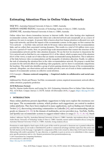
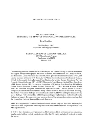
WSEAS TRANSACTIONS on SYSTEMSkinmChun-Yao Lee, Hong-Chan Chang, Hung-Cheng ChenThe operating load k could be instead of initialload ki or ultimate load ku, because the simplifiedmodel (12) ignores the minor effect of the ultimateand initial load of a transformer. The followingsections will use the simplified models to calculatethe elapsed life of a transformer.In observing characteristics of a transformer intemperature using (12), some variables of (8)-(11)are assumed to be constant. Fig. 1 shows the plots oftemperatures of a transformer with respect tochanges in loading level of the transformer. Thetemperature rises in oil ΘTO by (10) and in windingratio of initial load to be carried to 100%rating.empirically derived exponent used tocalculate the variation of ΘTO withchanges in load.empirically derived exponent used tocalculate the variation of Θ H withchanges in load.2.2 Load assumptionSeveral precise temperatures used in (4)-(7) can beobtained from the initial load ki and the ultimateload ku. In practice, the ki is close to ku when theduration of operation is short enough. Thus, theminor load difference between the initial andultimate state in this paper is neglected to facilitate aquick calculation, especially in the event of anemergency overloading.From (4)-(7), the assumption, k ki ku, yieldsthe following equations (8) and (9), ΘTO ,U ΘTO ,i k2R 1 ΘTO , R R 1 Θ H by (11) are also given. This means the finalhottest-spot temperature Θ Hdetermined by managing the load k when theambient temperature Θ A is assumed to be constant[10].For the purpose of simulation in this paper, somevalues in (8)-(12) are assumed to be constants, asfollows : n 0.42 , Θ A 25 C , m 0.8 , R 1.0 ,normal insulation life 180,000 Θ H , R 40 C , ΘTO , R 45 C .n Θ H ,U Θ H ,i Θ H , R k 2 m .(8)hours,(9)160From (2) and (3), the assumption, k ki ku,yields the following equations (10) and (11), k2R 1 ΘTO , R R 1 ΘHTemperature (degrees C) ΘTO ΘTO ,iin (12) can ben Θ H Θ H ,i Θ H , R k 2 m(10)(11)2.3 Simplified temperature model Θ TO Θ H140ΘA120604020Based on the aforementioned load assumption in (8)- (11) and the fundamental temperatures model in(1), the simplified hottest-spot temperature Θ H1.11.21.3Ratio of load[ k S1.4S rated ]1.5Fig. 1. Transformer temperatures.model is shown as below,2.4 Equivalent aging factor modelΘ H Θ A ΘTO Θ HFor estimating the accumulation of the effect intemperatures, the equivalent life (in hours) at thereference temperature that will be consumed in agiven time period for the given temperature cycle isthe following [8]:n(12) k2R 1 2m Θ A ΘTO , R Θ H , R k . R 1 ISSN: 1109-27771351Issue 11, Volume 7, November 2008
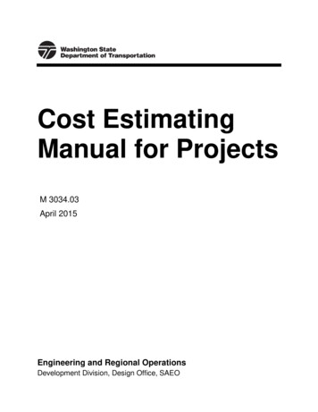
WSEAS TRANSACTIONS on SYSTEMSChun-Yao Lee, Hong-Chan Chang, Hung-Cheng Chen N N FEQA FAA, n tn tn n 1 n 1 the final state, when dielectric stress, short circuitstress, or mechanical movement could occur innormal rated service and cause an electrical failure,is called normal insulation life in (15).(13)where n is an index of the time interval, N is thetotal number of time intervals, Δtn is time interval,hours. A qualitative assessment of the lifeessentially incorporates the hottest-spot temperatureΘ H in (14) what is called an accelerated aging3 Case Study3.1 System description and associated dataAccording to the measured data gotten from [8], aworking tansformer is used to observe loads andtemperatures of the transformer. There are two casesto demonstrate the proposed model, which are themild overload case and short-time emergency loadcase, as shown in Table 1. The variation of the loadsand hottest-spot temperatures within a time periodof 24 hours are also illustrated in Table 1.factor [8]-[9]. The Θ H was mentioned in (12). 15,00015,000 FAA Exp .Θ H 273 383(14)2.5 Elapsed life modelFrom the IEEE standard C57.91-1995 and itscorrigendum, an elapsed model has been presentedto predict the transformer elapsed life of atransformer. The model can be used with controlledvariables providing the necessary transformervariables and can provide operators with the elapsedlife of a transformer. Elapsed life in the time periodis equivalent hours life consumed divided by thedefinition of total normal insulation life (hours) andmultiplied by 100, given as below [8]-[9]Elapsed life (%) FEQA t 100Normal insulation life.(1) Case 1 (Mild overload) : The transformer isworking regularly at mild overload from the 1sthour to the 24th hour of a duty day, and there are noextremely high measured temperatures in thetransformer.(2) Case 2 (Short-time emergency load) : Only theload at the 17th hour is extremely high, and themeasured temperatures in the short-time emergencyload case are higher than those in the mild overloadcase.The variations of load operating at mild overloadand short-time emergency load are shown in Fig. 2(a) and (b), respectively. The maximum load at themild overload case and short-time emergency loadcase are 1.2 (pu.) and 1.69 (pu.), respectively, in the17th hour. However, the temperature cannot be(15)For a given temperature of the transformerinsulation, the total time between the initial state,when the insulation is considered brand new, andTable 1 Transformer temperatures and loadsTime(hour-th)123456789101112Case 1Case 2Load (pu.) Temp. ( ) Load (pu.) Temp. ( SSN: 2Case 1Case 2Time(hour-th) Load (pu.) Temp.( ) Load (pu.) Temp. .897.993.287.6Issue 11, Volume 7, November 2008
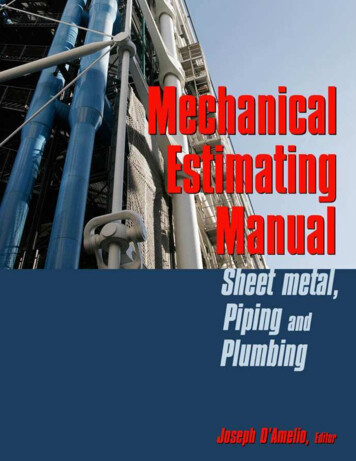
WSEAS TRANSACTIONS on SYSTEMSChun-Yao Lee, Hong-Chan Chang, Hung-Cheng Chen()1.8Case 1: Mild overload case1.81.5(17, 1.2)1.2Load (pu.)Load (pu.)1.50.90.6048121620(17, 1.69)Case 2: Short-time emergencyload case1.20.90.62404812Time (h)162024Time (h)(a)(b)130120110100908070(18, 130)Case 1: Mild overload case180Temperature (C)Temperature (C)Fig. 2. Load variations.(a) Mild overload case. (b) Short-time emergency load case048121620160(17, 180)Case 2: Short-time emergencyload case1401201002480600Time (h)4812162024Time (h)(a)(b)Fig. 3. Variations of hottest-spot temperatures.(a) Mild overload case. (b) Short-time emergency load case.1.2(pu.). The highest temperature point shows upwhen the operating load is 1.08(pu.). Thephenomenon is called temperature lag in this paper.In addition, when the operating load decreases andback to the end point of Fig. 4(a), 0.79(pu.), thetemperature is larger than the temperature when theoperating load is around 0.79(pu.) in the section 1 ofFig. (4). At this moment, the transformer keeps partof the heat, and the characteristic will not the sameas the situation from the beginning.In Fig. 4(b), the highest temperature of the shorttime emergency load case is 180 ( C) when theoperating load is 1.69 (pu.) at the 17th hour. At the18th hour, the load decreases largely and suddenlyand the temperature also decreases largely. Thetemperature lag is not much conspicuous as themild overload case of Fig. 4(a).reflected immediately from the load increasingbecause of the physical property of transformers,which means the temperature of transformer needthe time to accumulate he
From the IEEE standard C57.91-1995 and its corrigendum, an elapsed model has been presented to predict the transformer elapsed life of a transformer. The model can be used with controlled variables providing the necessary transformer variables and can provide operators with the elapsed life of a transformer. Elapsed life in the time period is equivalent hours life consumed divided by the .