Transcription
Service Application ManualSAM Chapter 630-33Section 1MBy: Cecil R. Visger, Past International PipingREFRIGERANT PIPINGINTRODUCTIONIn recent years, manufacturers of condensing units have more and more gone to motor-compressor units and direct-drivecompressors, which means that the compressors are turning at motor speeds. These relatively high-speed compressorscannot operate without proper lubrication at all times. Even more than formerly, adequate oil return must be maintained.Proper piping is conducive to long life and minimum repairs to the equipment, such as reduction of damage to compressorsby broken valves, burned out bearings and scored cylinders by the lack of proper oil return; and damage to expansion valvesdue to wire drawing as a result of flash gases, to name only a few of the possible damages. After all, it is to the best interestof all to make the customer’s equipment operate as efficiently and economically as possible.The chief purpose of this discussion on refrigerant piping is to point out some of the precautions to be taken which affectthe life and efficiency of refrigerating equipment, and to offer some helpful suggestions in piping design, selection anderection.The author knows of nothing the user appreciates more, and which causes him to feel that he has received his money’sworth, than NEATNESS. That is something he can see and understand. The only way fittings will fit properly is to install thepiping runs plumb and level, except when otherwise necessary to pitch for proper drainage. The supporting of pipes is partof the job of neatness, and should be done as part of the permanent results as intended in the original engineered layout.The intervals or spacing of the supports will be governed by the type and size of pipe, but should be close enough to avoidany sagging between the supports.In order to be able to properly select the valves, fittings and pipe for an installation, and the connection of the equipment fora given job, the location of each piece of the equipment with relation to each other component must be determined. Theselocations decide the design of the piping as well as the size and length, and they also determine the necessary valves andfittings. The first thing to do then is to make a layout. For small installations, the layout may even be mental; but there shouldbe a thought-out plan before erection is started.To simplify our discussion we shall divide it into four sub-topics, namely:DISCHARGE OR HOT GAS LINESLIQUID LINESSUCTION LINES FOR R-12SIZING REFRIGERANT PIPINGMISCELLANEOUS.Copyright 1964, 2009, By Refrigeration Service Engineers Society.-1-
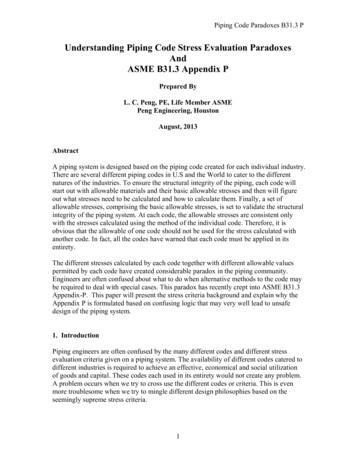
DISCHARGE OR HOT GAS LINESThe discharge or hot gas piping is as important as the other two lines. In many installations remote condensers are used,such as remote air-cooled condensers and evaporative condensers. Installations of these types present their problems,and should be piped to avoid excessive vibration, provide against the entrainment of oil, and for traps where necessary toprotect the equipment.The usual recommended maximum pressure drop for calculations of R-12 hot gas lines is 2 psig, and a minimum velocityof 1,500 fpm (feet per minute) in vertical, and 750 fpm in horizontal piping to maintain oil movement. These results can beobtained by referring to the manufacturers’ charts on “pipe sizing”.Care should be taken when connecting condensing units in parallel, and each with its own receiver. The hot gas linesshould be arranged so that the equalizer pipe between them is as short and as near the receivers as possible. (See Figure66F01.) This equalizer should be at least the next size smaller pipe than the discharge piping. When connecting two ormore compressors to one condenser, it is best to run a discharge line for each compressor directly into the condenser. If thismethod is not practical, each compressor discharge line should be connected to the main hot gas line in a “Y” or offset “T”,as in Figure 66F02A and Figure 66F02B, but never bull-headed, as in Figure 66F02C.Figure 66F01 Paralleling Condensing UnitsFigure 66F02A Y connection for paralleling the hot gas lines from two compressors to a condenser at a lower level (right).Figure 66F02B T or offset connection for paralleling the hot gas lines from two compressors to a condenser at a lower level (right).Copyright 1964, 2009, By Refrigeration Service Engineers Society.-2-
Figure 66F02C Bullhead (Wrong) and two permissible connections for paralleling two hot gas lines.The opposing flow of refrigerant gases, as shown in the left diagram in Figure 66F02C, can set up a turbulence that maycause pulsation in the piping. If the rise to the main hot gas line is over 4 or 5 ft, the branch lines should connect to the mainline above the center of the main line piping. Another suggested method for hot gas lines, when paralleling two compressors,is shown in Figure 66F03A.Another method of equalizing hot gas and receiver pressures and crankcase oil.If the condenser is as much as 8 or 10 ft above the compressor, provisions should be made to trap the oil and refrigerantthat might otherwise condense in the compressor heads when the compressors are stopped. (See Figure 66F03B andFigure 66F03C.) Using this method, oil and refrigerant will soon return to the system when the machine starts again, withoutdamage to valve plates or heads. For each additional 30 ft rise, another trap should be provided, dividing the amount of pipeproportionately to each trap. These traps should be made as short as fittings will permit.Copyright 1964, 2009, By Refrigeration Service Engineers Society.-3-
Figure 66F03C Separate hot gas lines from compressors to one condenser at a higher level, showing traps to prevent oil, and refrigerantfrom running back down into the compressor heads when the compressors stop.Figure 66F03C Similar connections to those in Figure 66F03B, except one hot gas line is used for both compressors. Note use of Yconnections and trap.If it is anticipated that the compressor temperature may be lower than the receiver temperature, and that the receiver islocated above the compressor, a check valve should be installed in the discharge piping near the receiver (Figure 66F03D).This will prevent refrigerant evaporated out of the receiver from condensing in the compressor head, and causing seriousdamage when the compressor starts.Figure 66F03DUse of check valve in hot gas line with condenser above the compressor if compressor is in cooler location thancondenser.EVAPORATIVE CONDENSER DISCHARGE LINESToday we are becoming concerned with water-saving devices, and one of these is the evaporative condenser. As has beenpreviously pointed out, the inlet and outlet piping of a multi-coil evaporative condenser should not be bull-head connected.The liquid outlet of an evaporative condenser should be piped downward from the condenser coil outlet and full size, beforea reduction in pipe size is made. This will avoid trapping any refrigerant in the coils of the evaporative condenser (Figure66F04A and Figure 66F04B).Copyright 1964, 2009, By Refrigeration Service Engineers Society.-4-
Figure 66F04A Bullhead tee connection (wrong) of hot gas line to two sections of evaporative condenser. T connection (right) of liquidlines. Note check valve in main liquid line to receiver.Figure 66F04B Correct hot gas and liquid lines for two section evaporative condenser.Again, we have the temperature difference affecting the refrigerant in the discharge circuit. To avoid any difficulty, it isrecommended that a check valve be installed at the inlet of the receiver, to prevent the refrigerant from recondensing out ofthe receiver back into the condenser coils, should the refrigerant temperature in the receiver exceed that in the evaporativecondenser coils.In cases of two or more evaporative condensers connected in parallel, the outlets should have a drop of at least 24” toprovide a static head to insure the condensed refrigerant draining into the receiver.Under certain weather conditions when the evaporative condenser is installed outside, and sometimes under what appearsto be normal operating conditions, liquid refrigerant will have a tendency to hang up in the condenser coil, caused by gasbinding in the receiver. This makes the system appear to be short of refrigerant, but after adding refrigerant and makinganother inspection, the system may be found to be over-charged. To help this condition, a control can be used to operatethe fan motor or spray pump to maintain a pressure in the condenser sufficient to overcome the pressure to the receiver.Copyright 1964, 2009, By Refrigeration Service Engineers Society.-5-
Another condition may be due to difference in levels, and may be corrected by repositioning the inlet and outlet of thecondenser piping, as shown in Figure 66F05.Figure 66F05 Evaporative condenser should be at higher level than its receiver. Note trap in liquid line and equalizer from top of receiverto hot gas line.In some installations, it may be necessary to raise the evaporative condenser to obtain a minimum of 18” drop between theoutlet of the condenser and the inlet to the receiver. Also, there must be a trap in this line at the lowest run to prevent gasfrom rising to the condenser coil. The small equalizer line from the receiver to the inlet piping of the condenser should havea valve for shutting off the receiver. The size of this pipe can be 3/8” up to 25 tons capacity, and 1/2” up to 60 tons.When designing a system, the engineer needs to maintain a solid column of liquid refrigerant to the flow control device,such as a thermostatic expansion valve, low-side float valve or high-side float valve, and make sure that column will stayat a reasonable working temperature. Any flashing of liquid refrigerant in the liquid line affects the capacity of flow-controldevices and of the evaporator. Also, it may cause damage to these controls, or may be noisy in operation.If the evaporator is located above the receiver, there are three important precautions that should apply:a. The liquid refrigerant should be delivered to the evaporator without flashing due to heating of liquid from surroundingair, or to drop in pressure due to friction in the piping or to static head.b. The expansion valve or other flow control devices should be selected according to the manufacturers’ rating for thecapacity required after pressure drop due to friction and static head have been considered.c.The liquid refrigerant should reach the flow control device sub-cooled at least 1 F below the exit temperature at thereceiver.The limits in height to which liquid refrigerant can be piped without flash gas differ among engineers, but a maximum rise of15 ft for R-12 is usually recommended. The controlling factor is the static head of the refrigerant at a given temperature. ForR-12 at 97 F, this is .55 psi per ft of rise, and .57 psi per ft of rise at 70 F. For R-22 at 97 F, it is .50 psi per foot of rise, and.52 psi per foot of rise at 70 F, so the maximum rise may be a foot or so more than for R-12.Several steps can be taken to reduce flash gas in lifts higher than that mentioned above:1. Increase liquid pipe size one size over the calculated size, to reduce pressure drop due to pipe friction.2. Increase shut-off valves, strainers, solenoid valves and dryers to match above piping. These measures (1 and 2)will not reduce pressure drop due to static head.Copyright 1964, 2009, By Refrigeration Service Engineers Society.-6-
3. If, due to excessive static head, the above recommendations cannot be used a heat exchanger installed betweenthe suction and liquid line in (Figure 66F06A) to sub-cool the liquid will accomplish satisfactory results. It is importantthat the heat exchanger be installed in a position that will not allow oil to be trapped in the suction side of it, whichin turn reduces the oil level in the compressor.Figure 66F06A Use of heat exchanger in liquid and suction line to sub-cool the liquid in case of excessive static head.4. Another alternative is to locate the receiver on the same floor level and near the evaporator. This method will bemore applicable when a receiver is used with a shell and tube condenser-receiver or other type condenser.The following are precautions to be followed in liquid line piping that will improve the service of the equipment: Never locate a stop valve directly below a”Y” type strainer in a vertical pipe see left drawing (Figure 66F06B), asballs of solder, scale and foreign particles will drop into the valve when the flow of refrigerant ceases, causingdamage to the valve disc and seat, as the valve is turned to the closed position. Figure 66F06C and Figure 66F06Dshow suggested installations of stop valves and strainers in the liquid line. The use of an angle strainer usuallyeliminates one fitting.Figure 66F06B Stop valve directly beow strainer in vertical liquid line (Wrong).Figure 66F06C Stop valve ahead of angle strainer in horizontal liquid line (Right).Figure 66F06D Stop valve ahead of Y strainer in horizontal liquid line (Right). Dryers should be installed in a vertical position and the liquid fed upward. The large volume of the drier causes areduced velocity of the liquid. If the drier is placed in a horizontal position, oil may tend to separate out and fill thatCopyright 1964, 2009, By Refrigeration Service Engineers Society.-7-
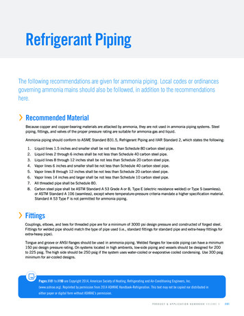
portion below the outlet, thus reducing the capacity of the drier. According to recent research, a good cleanablestrainer should be installed in the liquid line between the receiver and drier, to save the drier from becomingcontaminated with the foreign substances that may be in the refrigerating system. This procedure will improve andincrease the effectiveness of the drier. If the liquid line is run through an area with an ambient temperature above the design refrigerant temperature, thenthe line should be insulated the required thickness to protect it from outside heat gain.SUCTION LINESThe design and sizing of suction piping requires very careful consideration for the successful and efficient operation of eachpart of the equipment, since the suction line plays a most important part in the rapid return of oil to the compressor. If this onething is accomplished without abnormal pressure drop due to friction and without slugging, long compressor life will result.The paralleling of compressors and evaporators present many difficult problems. There are important designs to be practicedin paralleling either, and they are NOT the same.For installations of the evaporator or evaporators above the condensing unit, the suction line should be trapped by runningthe piping upward from the coil outlet trap, and as near the coil as possible, and to the height of the coil, to prevent thecondensed vapors remaining in the coil from draining directly into the compressor.Many times, the importance of proper piping design when inter-connecting evaporators is overlooked, and consequently theexpansion valve is condemned. To further explain the principle involved, Figure 66F07 compares a dribbling coffee cup tothe suction line. As the coffee is slowly poured, it will follow the outside of the cup to the lowest point. Now refer to the suctionline branches in this same picture. The shaded area represents small quantities of semi-vapor and liquid refrigerant. As thismixture flows from the top coil toward the lower coil, it tends to flow into the tee branch, following the wall of the tubing andspreading out as shown in cross section A-A, thus causing an effective temperature change of the TEV bulb, and in turnaffecting the proper functioning of the valve itself.Copyright 1964, 2009, By Refrigeration Service Engineers Society.-8-
Comparison of coffee dribbling from cup, and liquid following inside tube of suction line of lower evaporator. Locate T.E.V. bulbs on side,rather than top or bottom of suction line.SUCTION LINE DESIGN FOR MULTIPLE EVAPORATORSThe suction piping layout shown in Figure 66F08A and Figure 66F08B might lead to three coils in adjoining walk-in or reachin refrigerators. Suppose there are three walk-ins in Figure 66F08A, each with identical blower coils, each controlled by athermostat and a liquid line solenoid valve. If the suction piping were installed in the manner shown, it would interfere withthe proper operation of the TEV’s. For instance, assume that the left end cooler were requiring refrigeration, the condensingunit is running, and the solenoids were open on either or both of the coolers. It would be possible for the cold suction vaporsto drain into the left and coil and suction line and effect the operation of the TEV on this left end coil, since a trap has beeninstalled in the main suction piping preventing free drainage and return of the suction vapors and oil.Figure 66F08A Suction line from three adjacent refrigerators with trap in main line (Wrong).Figure 66F08B Same refrigerators as in Figure 66F08A, but with trap in each of the three branch suction lines (Right).The solution to this problem is shown in Figure 66F08B. Here the trap in the main suction line has been removed, and thebranch suction lines from each blower coil have been connected into the top of the main suction line, thus preventing thedraining of refrigerant from one coil into another.Notice how the piping from the unit in Figure 66F09A has been rearranged in Figure 66F09B with the same number offittings, to prevent suction vapors from the upper coil draining into the lower one.Figure 66F09A Upper coil of two evaporators in parallel can drain into lower coil (Wrong).Copyright 1964, 2009, By Refrigeration Service Engineers Society.-9-
Figure 66F09BSuction piping of Figure 66F09A rearraged to provide trap (Right).When evaporators are stacked in banks, one on top of the other, precautions should be taken to pipe them so that thedraining vapors from the upper coil do not have a chance to affect the control of the coil or coils below. Figure 66F10A is adiagram of the wrong method, while Figure 66F10B shows the right method of piping such an installation.Two air-conditioning coils stacked in a vertical bank. Upper coil can drain into lower (Wrong).Copyright 1964, 2009, By Refrigeration Service Engineers Society.-10-
Piping of Figure 66F10A rearranged to provide trap (Right).Following the recommendations of cold plate manufacturers, cold plates should be piped so the refrigerant enters thebottom opening, and with a maximum of 75 sq ft of surface in any one circuit. As in the case of other suction piping, thereturn or suction pipe from each plate or bank of plates fed by one TEV should be connected into the top or at a 45 angledownward to the main suction line, as illustrated in Figure 66F10C and 66F10D. This is to maintain proper refrigerantcontrol, as previously explained.Copyright 1964, 2009, By Refrigeration Service Engineers Society.-11-
Figure 66F10C Piping layout for two parallel banks of vertical overhead plate coils.Figure 66F10D Piping layout for two parallel banks of horizontal plate coils in rack.Copyright 1964, 2009, By Refrigeration Service Engineers Society.-12-
Occasionally, it is necessary to install the condensing unit several feet above the evaporator. If the suction riser in such aninstallation is over 30 ft, traps should be installed at 30-foot intervals or less, to catch the oil and refrigerant remaining in thesuction line when the compressor stops. When the compressor starts again, the oil and refrigerant will gradually return tothe compressor, pushed by the velocity of the vapors through the open portion of the trap. Otherwise, this oil and refrigerantmight come back to the compressor as a “slug” and damage it.Along with high-speed compressors has come suction capacity controls and cylinder unloaders. These devises have broughtabout the problems of maintaining riser velocity and suction lift, which will provide continuous oil return to compressors.During the running cycle the reduction of capacity may be as much as 25%, thus reducing the velocity of the suction gaswhich will be below the required velocity to entrain and return sufficient oil to the compressor.Most high-speed compressors have some type of oil pump, or are designed to provide forced lubrication to the bearings.At these motor speeds all bearings must have full lubrication at all times. A matter of minutes without sufficient oil and thebearings will become damaged.To provide for oil return during the reduced capacity period, where the main suction line or compressor are above theevaporator, a two-pipe or double riser can be used (Figure 66F11). The two pipes should be sized with a combined capacityfor full compressor load to maintain a velocity of 1,500 fpm, and the smaller pipe selected with a capacity to maintain therequired velocity with the compressor operating at it’s minimum capacity.Figure 66F11Two vertical parallel sections of a suction line from two evaporators in multiple operated by condensing unit at higher leveland provided with capacity reduction as load decreases.This two-pipe riser is made by installing a tee in the suction line below the level of the outlet of the coil or coils, with thebranch opening pointing upward. DO NOT reduce the run of the tee. This would make a trap in the wrong place. It would benecessary to reduce or use a tee with branch size of the selected small pipe size. On the down stream side of the tee makea trap as short as fittings will permit. When using solder fittings, this can be done with two 45 street ells and one 90 streetell. (See Figure 66F11.) If a reduction is necessary to accommodate the larger pipe, put the reducer immediately after thetrap. Both riser pipes are run high enough so that they enter the main suction line in the top or on a 45 angle downward.This design prevents any refrigerant from draining back, once it has reached the main suction line. From the point wherethese two pipes enter the main suction line, the suction piping should be pitched or sloped at least 1” for every 20 ft, towardthe compressor. This latter recommendation is good practice in piping all suction lines.Now that we have installed a two-pipe riser in the suction line, how does it function? As suction vapor volume is reduced, sois the velocity in a certain size suction pipe. Since the compressor capacity reduction is controlled by suction pressure, oilin the suction gas, with its reduced velocity, will separate out in the trap and seal it, causing the refrigerant vapors to passup the small pipe. Then, as the suction pressure builds up, creating sufficient pressure difference on each side of the trap,the trap seal will be broken and the vapors passing over the oil will gradually pick up all the oil in the trap and return it to thecompressor.Copyright 1964, 2009, By Refrigeration Service Engineers Society.-13-
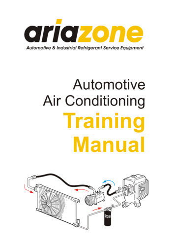
For systems with controlled suction capacity and a short suction line to just above the evaporator, minimum velocity forproper oil return can be maintained by reducing the riser to a size equal to the size pipe required for minimum velocity at thelowest capacity of the compressor. In making the turn at the top of this riser, use an elbow the same size as the riser; thenincrease the piping to the full suction line size.SIZING REFRIGERANT PIPINGPressure drop in refrigerant piping has been mentioned previously, but needs to be considered again in planning for theerection of the piping. Referring to Table 66T12A, a 1-1/8” 90 wrought elbow equals 1.85 ft of the same size pipe, andfor a 45 wrought elbow, the equivalent is 1 ft. of pipe or nearly 50 % less pressure-drop through a 45 elbow than for a 90 elbow. In making short offsets, minimize pressure drop by using a 90 and a 45 elbow or two 45 elbows rather than two90 elbows.Table 66T12A Equivalent resistance of copper fittings and valves in feet of copper tubing of same size. Length in Feet of Pipe tobe Added to Actual Length of Run Owing to Fittings.90 elbowCopper pipe size (O.D. in.)WroughtCast45 elbowTeeGate valveGlobe valveAngle 18.61.7100.048.0It is economical to use angle valves instead of straight-through globe valves. The saving in this practice can be seen ina study of the pressure drop through these valves in this same chart. It will be noted that angle valves have about 1/2 thepressure drop as that of globe valves. In many cases an angle valve can be used to make a turn instead of an elbow, thusconserving one fitting and reducing the leak potential at least by two.The foregone information and a mental or drawn plan of installation are necessary before any attempt can be made to selectthe pipe size. For example, in Figure 66F16 you see a proposed air conditioning installation. The condensing unit is 15 hpselected for R-12 at 40 F suction temperature and 100 F condensing temperature, hence the load will be about 15 tons or180,000 Btu/per hr. To temporarily select the suction piping for 2 psig pressure drop, 100 F condensing and 40 F suctiontemperatures, refer to the chart, (Figure 66F17), pressure drops in refrigerant lines for R-12. It is found that it is near 2-1/8”pipe.Figure 66F16 Typical 15 HP air-conditioning installation with dimensioned piping layout.Copyright 1964, 2009, By Refrigeration Service Engineers Society.-14-
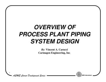
Figure 66F17 Pressure Drops in Refrigerant Lines Freon 12. Figured for type L copper tubing. For iron pipe subtract 1/8”from copper tubing size to find nominal iron pipe size. Multiply copper pressure by 16.In order to be within the limitations, make a calculation including the fittings and valves, thus:To use the chart in Figure 66F17, follow these instructions:In the upper right-hand corner you will find no indication for 15 tons, but you can select a spot half-way between 10 and 20tons. Imagine a vertical line there, and follow it down until it intersects with the slanting 40 Evaporator Temperature line.From this intersection, run a horizontal line toward the left edge of the chart.Next, we have assumed a 100 condensing temperature and have allowed a maximum pressure drop in the suction line of 2psig; so, at the bottom of the chart, find the point where the horizontal 100 condenser line intersects the diagonal pressuredrop line marked “2.” From this intersection, run a line upward until it intersects the horizontal line you drew toward the leftof the chart from the 15 tons and 40 evaporator intersection.Where these two lines meet is the size of suction tubing to use (indicated by another set of slanting diagonals, with pipesizes on them). However, the intersection does not fall exactly on any size, but is just below the diagonal line for 2-1/8” tubesize, and much above the diagonal line for the 1-5/8” tube size.Copyright 1964, 2009, By Refrigeration Service Engineers Society.-15-
Since the selected pipe is under the 100 ft in length, as noted in the chart, by using 2-1/8” suction line for this installation,proper oil return with a minimum pressure drop can be expected.Liquid and hot gas piping can be selected in the same manner as the suction piping, except with maximum allowablepressure-drop being in the 5 to 7 psig range.Table 66T12A, Table 66T12B, Table 66T13, Table 66T14A, Table 66T14B, and Table 66T15 are for the selection of refrigerantliquid and suction piping for open self-service refrigerated store fixtures, and for other refrigerated fixtures having the sameBtu/hr load and held at approximately the same temperatures.Table 66T14A R-12 Piping Requirements for Self-Service Dairy & Delicatessen Cases and for other refrigerated fixtures havingthe same BTU/hr load and held at approximatly the same temperatures.Condensing unit, hpRefrigerant line sizesOverall caseAir-cooled (or air andFirst case*Second caseThird uctionLiquidSuction6 ft 3 in.3/43/43/85/812 ft 3 in.1-1/21-1/23/85/83/87/818 ft 4 in.323/85/83/87/83/87/824 ft 5 in.33/85/83/87/83/87/830 ft 5 in.53/85/83/87/83/87/836 ft 6 in.53/85/83/87/83/87/8Condensing unit, hpOverall caseAir-cooled (or air andFourth caselengthwater)WatercooledLiquidSuction6 ft 3 in.3/43/412 ft 3 in.1-1/21-1/218 ft 4 in.3224 ft 5 in.31/21 1/830 ft 5 in.51/21 1/836 ft 6 in.51/21 1/8* 1st case is farthest one from condensing unit.** Overall dimensions are the total length of case to the nearest inch.Copyright 1964, 2009, By Refrigeration Service Engineers Society.Refrigerant line sizesFifth caseLiquidSuction1/21/21 1/81 1/8Sixth caseLiquidSuction1/21 3/8-16-
Recommendation based on designed 20 F evaporator and 28 F. shelf temperature when operatingin a 90 F store.Table 66T14B R-12 Piping Requirements for Refrigerated Vegetables Display Cases and for other refrigerated fixtures having thesame BTU/hr load and held at approximatly the same temperatures.Condensing unit, hpRefrigerant line sizesNumber ofAir-cooled (or airWaterFirst case*Second caseThird caseFourth casecasesand nLiquidSuction1 (8 ft)3/43/41/45/81 (11 ft)13/43/85/82 (8 ft)1-1/213/85/83/87/81 (8 ft)1 (11 ft)21-1/23/85/83/87/82 (11 ft)21-1/23/85/83/87/81 (8 ft)2 (11 ft)323/85/83/87/81/21 1/83 (11 ft)333/85/83/87/81/21 1/81 (8 ft)3 (11 ft)33/85/83/87/81/21 1/81/21 1/84 (11 ft)33/85/83/87/81/21 1/81/21 1/8* 1st case is farthest one from condensing unit.Recommendation based on designed 20 F evaporator and 38 F shelf temperature whenoperating in a 90 F store temperature.Table 66T15 R-22 Piping Requirements for Frozen Food Self-Service Display Cases and for other refrigerated fixtures having thesame BTU/hr load and held at approximatly
locations decide the design of the piping as well as the size and length, and they also determine the necessary valves and fittings. The first thing to do then is to make a layout. For small installations, the layout may even be mental; but there