Transcription
Refrigerant PipingThe following recommendations are given for ammonia piping. Local codes or ordinancesgoverning ammonia mains should also be followed, in addition to the recommendationshere.››Recommended MaterialBecause copper and copper-bearing materials are attacked by ammonia, they are not used in ammonia piping systems. Steelpiping, fittings, and valves of the proper pressure rating are suitable for ammonia gas and liquid.Ammonia piping should conform to ASME Standard B31.5, Refrigerant Piping and IIAR Standard 2, which states the following:1.Liquid lines 1.5 inches and smaller shall be not less than Schedule 80 carbon steel pipe.2.Liquid lines 2 through 6 inches shall be not less than Schedule 40 carbon steel pipe.3.Liquid lines 8 through 12 inches shall be not less than Schedule 20 carbon steel pipe.4.Vapor lines 6 inches and smaller shall be not less than Schedule 40 carbon steel pipe.5.Vapor lines 8 through 12 inches shall be not less than Schedule 20 carbon steel pipe.6.Vapor lines 14 inches and larger shall be not less than Schedule 10 carbon steel pipe.7.All threaded pipe shall be Schedule 80.8.Carbon steel pipe shall be ASTM Standard A 53 Grade A or B, Type E (electric resistance welded) or Type S (seamless);or ASTM Standard A 106 (seamless), except where temperature-pressure criteria mandate a higher specification material.Standard A 53 Type F is not permitted for ammonia piping.››FittingsCouplings, elbows, and tees for threaded pipe are for a minimum of 3000 psi design pressure and constructed of forged steel.Fittings for welded pipe should match the type of pipe used (i.e., standard fittings for standard pipe and extra-heavy fittings forextra-heavy pipe).Tongue and groove or ANSI flanges should be used in ammonia piping. Welded flanges for low-side piping can have a minimum150 psi design pressure rating. On systems located in high ambients, low-side piping and vessels should be designed for 200to 225 psig. The high side should be 250 psig if the system uses water-cooled or evaporative cooled condensing. Use 300 psigminimum for air-cooled designs.Pages J181 to J190 are Copyright 2014, American Society of Heating, Refrigerating and Air-Conditioning Engineers, Inc.(www.ashrae.org). Reprinted by permission from 2014 ASHRAE Handbook-Refrigeration. This text may not be copied nor distributed ineither paper or digital form without ASHRAE’s permission.PRODUCT & APPLICATION HANDBOOK VOLUME VJ181
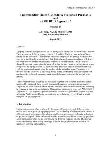
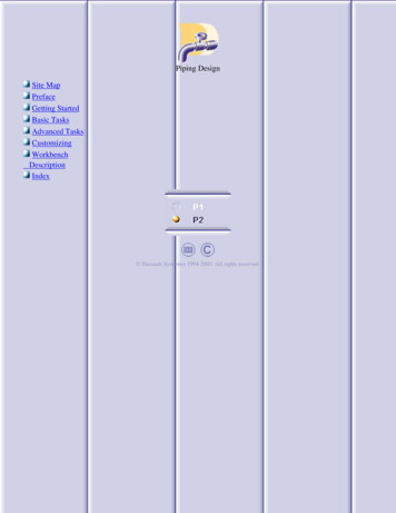
TECHNICAL RESOURCESRefrigerant PipingSaturated Suction Temperature, F-60Steel Line Size-40-20IPSSCH t 0.25 F p 0.046 t 0.50 F p 0.092 t 0.25 F p 0.077 t 0.50 F p 0.155 t 0.25 F p 0.123 t 0.50 F p .450.570.840.991.441 /14400.821.211.532.242.653.841 7911.26NOTE: Capacities are in tons2 1/2403.945.787.2310.5612.5018.03of refrigeration resulting in a3407.1010.3013.0018.8122.2332.09line friction loss ( p in psi per44014.7721.2126.8138.6245.6665.81100 ft equivalent pipe length),54026.6638.6548.6870.0782.70119.60with corresponding change ( t64043.4862.8379.18114.26134.37193.44in F per 100 ft) in 812ID*264.07379.88477.55686.10808.931,157.59is the same as the nominal pipeSaturated Suction Temperature, F0Steel Line Size20size.40IPSSCH t 0.25 F p 0.184 t 0.50 F p 0.368 t 0.25 F p 0.265 t 0.50 F p 0.530 t 0.25 F p 0.366 t 0.50 F p .342.503.603.684.691 /14404.306.216.639.529.7612.421 27.7428.4536.082 64.562,790.372,862.233,613.23Table 1 Suction Line Capacities in Tons for Ammonia with Pressure Drops of 0.25 and 0.50 F per 100 ft EquivalentJ182Q U E S T I O N S ? C A L L 4 1 0 . 7 9 9 . 6 2 0 0 O R V I S I T W W W. B A LT I M O R E A I R C O I L . C O M* The inside diameter of the pipe
››Pipe JointsJoints between lengths of pipe or between pipe and fittings can be threaded if the pipe size is 1.25 in. or smaller. Pipe 1.5inches or larger should be welded. An all-welded piping system is superior.Threaded Joints. Many sealants and compounds are available for sealing threaded joints. The manufacturer’s instructionscover compatibility and application method. Do not use excessive amounts or apply on female threads because any excess cancontaminate the system.Welded Joints. Pipe should be cut and beveled before welding. Use pipe alignment guides to align the pipe and provide a propergap between pipe ends so that a full penetration weld is obtained. The weld should be made by a qualified welder, using properprocedures such as the Welding Procedure Specifications, prepared by the National Certified Pipe Welding Bureau (NCPWB).Gasketed Joints. A compatible fiber gasket should be used with flanges. Before tightening flange bolts to valves, controls, orflange unions, properly align the pipe and bolt holes. When flanges are are used to straighten pipe, they put stress on adjacentvalves, compressors, and controls, causing the operating mechanism to bind. To prevent leaks, flange bolts are drawn up evenlywhen connecting the flanges. Flanges at compressors and other system components must not move or indicate stress when allbolts are loosened.Union Joints. Steel (3000 psi) ground joint unions are used for gage and pressure control lines with screwed valves and forjoints up to 0.75 in. When tightening this type of joint, the two pipes must be axially aligned. To be effective, the two parts ofthe union must match perfectly. Ground joint unions should be avoided if at all possible.››Pipe LocationPiping should be at least 7.5 ft above the floor. Locate pipes carefully in relation to other piping and structural members,especially when the lines are to be insulated. The distance between insulated lines should be at least three times the thicknessof the insulation for screwed fittings, and four times for flange fittings. The space between the pipe and adjacent surfacesshould be three-fourths of these amounts.Hangers located close to the vertical risers to and from compressors keep the piping weight off the compressor. Pipe hangersshould be placed no more than 8 to 10 ft apart and with in 2 ft of a change in direction of the piping. Hangers should bedesigned to bear on the outside of insulated lines. Sheet metal sleeves on the lower half of the insulation are usually sufficient.Where piping penetrates a wall, a sleeve should be installed and where the pipe penetrating the wall is insulated, it must beadequately sealed.Piping to and from compressors and to other components must provide for expansion and contraction. Sufficient flange or unionjoints should be located in the piping that components can be assembled easily during initial installation and also disassembledfor servicing.Reprinted by permission from 2014 ASHRAE Handbook-Refrigeration. Copyright 2014.PRODUCT & APPLICATION HANDBOOK VOLUME VJ183
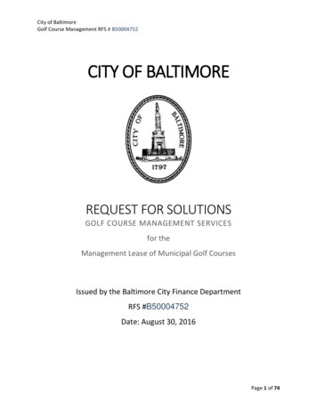
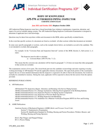
TECHNICAL RESOURCESRefrigerant Piping››System Practices for Ammonia RefrigerantSuction Lines ( t 1 F)Steel Line SizeIPSDischargeLinesSaturated Suction Temperature, FSCH-40 p 0.31-20 p 0.490 p 0.7320 p 1.0640 p 1.46 t 1 F p 2.95Steel Line SizeIPSLiquid LinesSCHVelocity 100 fpm p 2.0 psi t 0.7 18043.8106.41 /14403.25.68.913.619.936.51 1/48078.1228.61 1/2404.98.413.420.529.954.81 811.42 1/24015.325.941.563.292.1168.52 2ID*--Table 2. Suction, Discharge, and Liquid Line Capacities in Tons for Ammonia (Single- or High-Stage Applications)Notes:1. Table capacities are in tons of refrigeration. p pressure drop due to line friction, psiper 100 ft of equivalent line length t corresponding change in saturationtemperature, F per 100 ft2. Line capacity for other saturationtemperatures t and equivalent lengths Lc0.55Actual tTable LcLine capacity Table capacityXActual Lc Table t3.Saturation temperature t for othercapacities and equivalent lengths LcCondensingTemperature, F Suction 891.001.115. Discharge and liquid line capacities are based on 20 F suction.Evaporator temperature is 0 F. The capacity is affected less than 3%when applied from -40 to 40 F extremes.*The inside diameter of the pipe is the same as the nominal pipe size.1.8Actual Lc Actual Capacity t Table tXTable LcTable CapacityJ1844. Values in the table are based on 90 F condensing temperature.Multiply table capacities by the following factors for other condensingtemperatures:Q U E S T I O N S ? C A L L 4 1 0 . 7 9 9 . 6 2 0 0 O R V I S I T W W W. B A LT I M O R E A I R C O I L . C O M
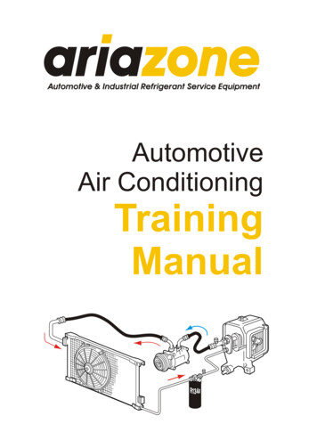
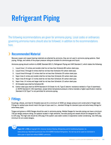
Pumped LiquidOverfeed RatioThermosiphon Lubricant Cooling LinesGravity Flow, c 1000 Btu/h5:1High-PressureLiquid at 3 psi aHot-Gas Defrost aEqualizer HighSide 5261348100---1 1/493.5705628620150---1 1/214611087.543930225200120203362NominalSize, in.3:14:11/2103/423342502001016503004703002 311596Table 3. Liquid Ammonia line capacities (capacity in tons of refrigeration, except as noted)Source: Wile (1977)a. Hot-gas line sizes are based on 1.5 psi pressure drop per 100 ft of equivalent length at 100 psig discharge pressureand 3 times the evaporator refrigeration capacity.b. Line sizes are based on experience using total system evaporator tons.c. From Frick Co. (1995). Values for line sizes above 4 in are extrapolated.››Pipe SizingTable 1 presents practical suction line sizing data based on 0.25 F and 0.50 F differential pressure drop equivalent per 100 ftfor the total equivalent length of pipe, assuming no liquid in the suction line. Table 2 lists data for sizing suction and dischargelines at 1 F differential pressure drop equivalent per 100 ft equivalent length of pipe, and for sizing liquid lines at 100 fpm.Charts prepared by Wile (1977) present pressure drops in saturation temperature equivalents. For a complete discussion ofthe basis of these line sizing charts, see Timm (1991). Table 3 presents line sizing information for pumped liquid lines, highpressure liquid lines, hot-gas defrost lines, equalizing lines, and thermosiphon lubricant cooling ammonia lines.››ValvesStop Valves. These valves, also commonly called shutoff or isolation valves, are generally manually operated, although motoractuated units are available. ASHRAE Standard 15 requires these valves in the inlet and outlet lines to all condensers,compressors, and liquid receivers. Additional valves are installed on vessels, evaporators, and long lengths of pipe so theycan be isolated in case of leaks and to facilitates pumping out for servicing and evacuation. Sections of liquid piping that canexperience hydraulic lockup in normal operation must be protected with a relief device (preferably vented back into the system).Only qualified personnel should be allowed to operate stop valves.Installing globe-type stop valves with the valve stems horizontal lessens the chance (1) for dirt or scale to lodge on the valveseat or disk and cause it to leak or (2) for liquid or lubricant to pocket in the area below the seat. Wet suction return lines(recirculation system) should use angle valves or globe valves (with their stems horizontal) to reduce the possibility of liquidpockets and to reduce pressure drop.Reprinted by permission from 2014 ASHRAE Handbook-Refrigeration. Copyright 2014.PRODUCT & APPLICATION HANDBOOK VOLUME VJ185
TECHNICAL RESOURCESRefrigerant PipingWelded flanged or weld-in-line valves are desirable for all line sizes; however, screwed valves may be used for 1 1/4” andsmaller lines. Ammonia globe and angle valves should have the following features: Soft seating surfaces for positive shutoff (no copper or copper alloy) Back seating to permit repacking the valve stem while in service Arrangement that allows packing to be tightened easily All-steel construction (preferable) Bolted bonnets above 1 in., threaded bonnets for 1 in. and smallerConsider seal cap valves in refrigerated areas and for all ammonia piping. To keep pressure drop to a minimum, consider anglevalves (as opposed to globe valves).Control Valves. Pressure regulators, solenoid valves, check valves, gas-powered suction stop valves, and thermostatic expansionvalves can be flanged for easy assembly and removal. Alternative weld-in line valves with nonwearing body parts are available.Valves 1.5 in. and larger should have welded companion flanges. Smaller valves can have threaded companion flanges.A strainer should be used in front of self-contained control valves to protect them from pipe construction material and dirt.Solenoid Valves. Solenoid Valve stems should be upright with their coils protected from moisture. They should have flexibleconduit connections, where allowed by codes, and an electric pilot light wired in parallel to indicate when the coil is energized.Solenoid valves for high-pressure liquid feed to evaporators should have soft seats for positive shutoff. Solenoid valves for otherapplications, such as in suction lines, hot-gas lines, or gravity feed lines, should be selected for the pressure and temperature ofthe fluid flowing and for the pressure drop available.Relief Valves. Safety Valves must be provided in conformance with ASHRAE Standard 15 and Section VIII, Division 1, of theASME Boiler and Pressure Vessel Code. For ammonia systems, IIAR Bulletin 109 also addresses the subject of safety valves.Dual relief valve arrangements enable testing of the relief valves (Figure 1). The three-way stop valve is constructed so that it isalways open to one of the relief valves if the other is removed to be checked or repaired.››Isolated Line SectionsSections of piping that can be isolated between hand valves or checkvalves can be subjected to extreme hydraulic pressures if cold liquidrefrigerant is trapped in them and subsequently warmed. Additionalsafety valves for such piping must be provided.››Insulation and Vapor RetardersInsulation and effective vapor retarders on low-temperature systemsare very important. At low temperatures, the smallest leak in thevapor retarder can allow ice to from inside the insulation, which cantotally destroy the integrity of the entire insulation system. The resultcan cause a significant increase in load and power usage.Figure 1. Dual Relief Valve Fitting For AmmoniaReprinted by permission from 2014 ASHRAE Handbook-Refrigeration. Copyright 2014.J186Q U E S T I O N S ? C A L L 4 1 0 . 7 9 9 . 6 2 0 0 O R V I S I T W W W. B A LT I M O R E A I R C O I L . C O M
PRODUCT & APPLICATION HANDBOOK VOLUME VJ187
Reprinted by permission from 2014 ASHRAE Handbook-Refrigeration. Copyright 2014.J188Q U E S T I O N S ? C A L L 4 1 0 . 7 9 9 . 6 2 0 0 O R V I S I T W W W. B A LT I M O R E A I R C O I L . C O M
PRODUCT & APPLICATION HANDBOOK VOLUME VJ189
Reprinted by permission from 2014 ASHRAE Handbook-Refrigeration. Copyright 2014.J190Q U E S T I O N S ? C A L L 4 1 0 . 7 9 9 . 6 2 0 0 O R V I S I T W W W. B A LT I M O R E A I R C O I L . C O M
Sep 14, 2015 · Tongue and groove or ANSI flanges should be used in ammonia piping. Welded flanges for low-side piping can have a minimum . 150 psi design pressure rating. On systems located in high ambients, low-side piping