Transcription
INSTRUCTION MANUALLWS DielectricLeaf Wetness SensorRevision: 2/17C o p y r i g h t 2 0 0 8 - 2 0 1 7C a m p b e l l S c i e n t i f i c , I n c .
AssistanceProducts may not be returned without prior authorization. The followingcontact information is for Canadian and international clients residing incountries served by Campbell Scientific (Canada) Corp. directly. Affiliatecompanies handle repairs for clients within their territories. Please visitwww.campbellsci.ca to determine which Campbell Scientific company servesyour country.To obtain a Returned Materials Authorization (RMA), contact CAMPBELLSCIENTIFIC (CANADA) CORP., phone (780) 454-2505. After ameasurement consultant determines the nature of the problem, an RMAnumber will be issued. Please write this number clearly on the outside of theshipping container. Campbell Scientific’s shipping address is:CAMPBELL SCIENTIFIC (CANADA) CORP.RMA#14532 131 Avenue NWEdmonton, Alberta T5L 4X4CanadaFor all returns, the client must fill out a “Statement of Product Cleanliness andDecontamination” form and comply with the requirements specified in it. Theform is available from our web site at www.campbellsci.ca/repair. Acompleted form must be either emailed to repair@campbellsci.ca or faxed to(780) 454-2655. Campbell Scientific (Canada) Corp. is unable to process anyreturns until we receive this form. If the form is not received within three daysof product receipt or is incomplete, the product will be returned to the client atthe client’s expense. Campbell Scientific (Canada) Corp.f reserves the right torefuse service on products that were exposed to contaminants that may causehealth or safety concerns for our employees.
PrecautionsDANGER — MANY HAZARDS ARE ASSOCIATED WITH INSTALLING, USING, MAINTAINING, AND WORKING ON OR AROUNDTRIPODS, TOWERS, AND ANY ATTACHMENTS TO TRIPODS AND TOWERS SUCH AS SENSORS, CROSSARMS, ENCLOSURES,ANTENNAS, ETC. FAILURE TO PROPERLY AND COMPLETELY ASSEMBLE, INSTALL, OPERATE, USE, AND MAINTAIN TRIPODS,TOWERS, AND ATTACHMENTS, AND FAILURE TO HEED WARNINGS, INCREASES THE RISK OF DEATH, ACCIDENT, SERIOUSINJURY, PROPERTY DAMAGE, AND PRODUCT FAILURE. TAKE ALL REASONABLE PRECAUTIONS TO AVOID THESE HAZARDS.CHECK WITH YOUR ORGANIZATION'S SAFETY COORDINATOR (OR POLICY) FOR PROCEDURES AND REQUIRED PROTECTIVEEQUIPMENT PRIOR TO PERFORMING ANY WORK.Use tripods, towers, and attachments to tripods and towers only for purposes for which they are designed. Do not exceed designlimits. Be familiar and comply with all instructions provided in product manuals. Manuals are available at www.campbellsci.ca or bytelephoning (780) 454-2505 (Canada). You are responsible for conformance with governing codes and regulations, including safetyregulations, and the integrity and location of structures or land to which towers, tripods, and any attachments are attached. Installationsites should be evaluated and approved by a qualified personnel (e.g. engineer). If questions or concerns arise regarding installation,use, or maintenance of tripods, towers, attachments, or electrical connections, consult with a licensed and qualified engineer orelectrician.General Prior to performing site or installation work, obtain required approvals and permits. Use only qualified personnel for installation, use, and maintenance of tripods and towers, andany attachments to tripods and towers. The use of licensed and qualified contractors ishighly recommended. Read all applicable instructions carefully and understand procedures thoroughly beforebeginning work. Wear a hardhat and eye protection, and take other appropriate safety precautions whileworking on or around tripods and towers. Do not climb tripods or towers at any time, and prohibit climbing by other persons. Takereasonable precautions to secure tripod and tower sites from trespassers. Use only manufacturer recommended parts, materials, and tools.Utility and Electrical You can be killed or sustain serious bodily injury if the tripod, tower, or attachments you areinstalling, constructing, using, or maintaining, or a tool, stake, or anchor, come in contactwith overhead or underground utility lines. Maintain a distance of at least one-and-one-half times structure height, 6 meters (20 feet), orthe distance required by applicable law, whichever is greater, between overhead utility linesand the structure (tripod, tower, attachments, or tools). Prior to performing site or installation work, inform all utility companies and have allunderground utilities marked. Comply with all electrical codes. Electrical equipment and related grounding devices shouldbe installed by a licensed and qualified electrician.Elevated Work and Weather Exercise extreme caution when performing elevated work. Use appropriate equipment and safety practices. During installation and maintenance, keep tower and tripod sites clear of un-trained or nonessential personnel. Take precautions to prevent elevated tools and objects from dropping. Do not perform any work in inclement weather, including wind, rain, snow, lightning, etc.Maintenance Periodically (at least yearly) check for wear and damage, including corrosion, stress cracks,frayed cables, loose cable clamps, cable tightness, etc. and take necessary corrective actions. Periodically (at least yearly) check electrical ground connections.WHILE EVERY ATTEMPT IS MADE TO EMBODY THE HIGHEST DEGREE OF SAFETY IN ALL CAMPBELL SCIENTIFIC PRODUCTS,THE CLIENT ASSUMES ALL RISK FROM ANY INJURY RESULTING FROM IMPROPER INSTALLATION, USE, OR MAINTENANCE OFTRIPODS, TOWERS, OR ATTACHMENTS TO TRIPODS AND TOWERS SUCH AS SENSORS, CROSSARMS, ENCLOSURES, ANTENNAS,ETC.
PLEASE READ FIRSTAbout this manualPlease note that this manual was originally produced by Campbell Scientific Inc. (CSI) primarilyfor the US market. Some spellings, weights and measures may reflect this origin.Some useful conversion factors:Area:Length:Mass:Pressure:Volume:1 in2 (square inch) 645 mm21 in. (inch) 25.4 mm1 ft (foot) 304.8 mm1 yard 0.914 m1 mile 1.609 km1 oz. (ounce) 28.35 g1 lb (pound weight) 0.454 kg1 psi (lb/in2) 68.95 mb1 US gallon 3.785 litresIn addition, part ordering numbers may vary. For example, the CABLE5CBL is a CSI partnumber and known as a FIN5COND at Campbell Scientific Canada (CSC). CSC TechnicalSupport will be pleased to assist with any questions.About sensor wiringPlease note that certain sensor configurations may require a user supplied jumper wire. It isrecommended to review the sensor configuration requirements for your application and supply the jumperwire is necessary.
Table of ContentsPDF viewers: These page numbers refer to the printed version of this document. Use thePDF reader bookmarks tab for links to specific sections.1. Introduction . 12. Precautions . 13. Initial Inspection . 14. QuickStart . 25. Overview . 45.15.2Measurement . 4Leaf Mimicry . 46. Specifications. 57. Installation . 57.17.27.3Field Installation . 5Wiring . 6Programming. 77.3.1 Voltage Measurement . 77.3.2 Interpreting Data . 78. Maintenance . 89. Acknowledgement . 9AppendicesA. Importing Short Cut Code Into CRBasic Editor . A-1B. Example Programs. B-1B.1B.2Example CR1000 Program . B-1Example CR6 Program . B-27-1.7-2.7-3.LWS Dielectric Leaf Wetness Sensor . 6Top view of a typical LWS installation . 6Typical LWS response . 8Figuresi
Table of ContentsTablesB-1.B-2.CR1000 Example Wiring . B-1CR6 Example Wiring . B-2CRBasic ExamplesB-1.B-2.CR1000 Program for Measuring the LWS . B-1CR6 Program for Measuring the LWS . B-2ii
LWS Dielectric Leaf Wetness Sensor1.IntroductionDirect measurement of leaf wetness is problematic. Secure long-termattachment of a sensor to a representative living leaf is difficult. Leaf position,sun exposure, and health are in constant flux. To avoid these problems, leafwetness sensors have been developed to estimate by inference the wetness ofnearby leaves. The LWS estimates leaf surface wetness by measuring thedielectric constant of the sensor’s upper surface. The sensor is able to detect thepresence of miniscule amounts of water or ice. Individual sensor calibration isnot normally necessary.NOTE2.3.This manual provides information only for CRBasic dataloggers.It is also compatible with most of our retired Edlog dataloggers.For Edlog datalogger support, see an older manual atwww.campbellsci.com/old-manuals.Precautions READ AND UNDERSTAND the Safety section at the front of thismanual. Care should be taken when opening the shipping package to not damage orcut the cable jacket. If damage to the cable is suspected, contact CampbellScientific. Although the LWS is rugged, it should be handled as a precision scientificinstrument. Over time, the accumulation of dust and bird droppings can cause the dryoutput to rise. We recommend that the sensor be periodically cleanedusing a moist cloth, or when you detect elevated dry output. The LWS is intended only for applications wherein the dataloggerprovides short excitation, leaving the probe quiescent most of the time.Continuous excitation may cause the probe to exceed governmentspecified limits on electromagnetic emissions.Initial Inspection Upon receipt of the LWS, inspect the packaging and contents for damage.File damage claims with the shipping company. The model number and cable length are printed on a label at theconnection end of the cable. Check this information against the shippingdocuments to ensure the correct product and cable length are received.1
LWS Dielectric Leaf Wetness Sensor4.QuickStartShort Cut is an easy way to program your datalogger to measure the LWS andassign datalogger wiring terminals. Short Cut is available as a download onwww.campbellsci.com and the ResourceDVD. It is included in installations ofLoggerNet, PC200W, PC400, or RTDAQ.The following procedure shows using Short Cut to program the LWS.21.Open Short Cut. Click New Program.2.Select Datalogger Model and Scan Interval (default of 5 seconds is OKfor most applications). Click Next.
LWS Dielectric Leaf Wetness Sensor3.Under the Available Sensors and Devices list, select the Sensors Miscellaneous Sensors folder. Select LWS Dielectric Leaf WetnessSensor. Clickto move the selection to the Selected device window.Enter the Dry threshold (mV) and Wet threshold (mV) values (seeSection 7.3.2, Interpreting Data (p. 7), for information about determiningthe dry threshold and wet threshold values).4.After selecting the sensor, click Wiring Diagram to see how the sensor isto be wired to the datalogger. The wiring diagram can be printed now orafter more sensors are added.5.Select any other sensors you have, then finish the remaining Short Cutsteps to complete the program. The remaining steps are outlined in ShortCut Help, which is accessed by clicking on Help Contents Programming Steps.3
LWS Dielectric Leaf Wetness Sensor5.6.If LoggerNet, PC400, RTDAQ, or PC200W is running on your PC, and thePC to datalogger connection is active, you can click Finish in Short Cutand you will be prompted to send the program just created to thedatalogger.7.If the sensor is connected to the datalogger, as shown in the wiringdiagram in step 4, check the output of the sensor in the datalogger supportsoftware data display to make sure it is making reasonable measurements.Overview5.1MeasurementThe LWS measures the dielectric constant of a zone approximately 1 cm fromthe upper surface of the sensor. The dielectric constant of water ( 80) and ice( 5) are much higher than that of air ( 1), so the measured dielectric constantis strongly dependent on the presence of moisture or frost on the sensorsurfaces. The sensor outputs a mV signal proportional to the dielectric of themeasurement zone, and therefore proportional to the amount of water or ice onthe sensor surface.5.2Leaf MimicryThe LWS is designed to approximate the thermodynamic properties of mostleaves. If the specific heat of a typical leaf is estimated at 3750 J kg–1 K–1,density estimated at 0.95 g/cm3, and thickness estimated at 0.4 mm, then theheat capacity of the leaf is 1425 J m–2 K–1. This heat capacity is closelyapproximated by the thin (0.65 mm) fiberglass construction of the LWS, whichhas a heat capacity of 1480 J m–2 K–1. By mimicking the thermodynamicproperties of a real leaf, the LWS closely matches the wetness state of thecanopy.The sensor closely matches the radiative properties of real leaves. Healthyleaves generally absorb solar radiation in much of the visible portion of thespectrum, but selectively reject much of the energy in the near-infrared. Thesurface coating of the LWS absorbs well in the near-infrared region, but thewhite color reflects most of the visible radiation. Spectroradiometermeasurements indicate that the overall radiation balance of the sensor closelymatches that of a healthy leaf. During normal use, prolonged exposure tosunlight can cause some yellowing of the coating, which does not affect theprobe’s function. The surface coating is hydrophobic — similar to a leaf with ahydrophobic cuticle. The sensor should match the wetness state of these typesof leaves well, but may not match the wetness duration of pubescent leaves orleaves with less waxy cuticles.4
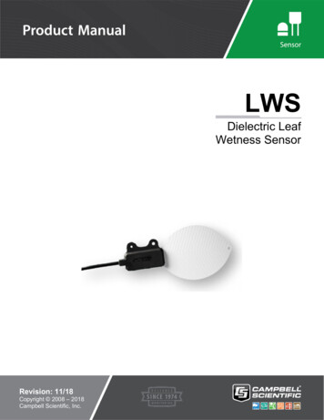
LWS Dielectric Leaf Wetness Sensor6.SpecificationsFeatures:7. Imitates characteristics of a leaf Does not require painting or calibration of individual sensors Detects trace amounts of water or ice on the leaf surface Compatible with Campbell Scientific CRBasic dataloggers:CR200(X) series, CR300 series, CR6 series, CR800 series, CR1000,CR3000, CR5000, and CR9000(X)Measurement Time:10 msExcitation:2.5 Vdc (2 mA) to 5.0 Vdc (7 mA)Minimum Excitation Time:10 mSOutput:10% to 50% of excitationOperating Temperature:–20 to 60 CProbe Dimensions:11.2 cm x 5.8 cm x .075 cmMaximum Lead Length:250 ftInterchangeability:Interchangeable without painting or individualcalibrationInstallationIf you are programming your datalogger with Short Cut, skip Section 7.2,Wiring (p. 6), and Section 7.3, Programming (p. 7). Short Cut does this work foryou. See Section 4, QuickStart (p. 2), for a Short Cut tutorial.7.1Field InstallationThe LWS is designed to be mounted on a small diameter rod. Deployment in aplant canopy or on a weather station mast is typical. Two holes in the sensorbody are available for mounting with zip ties or 4-40 bolts (FIGURE 7-1 andFIGURE 7-2).5
LWS Dielectric Leaf Wetness SensorFIGURE 7-1. LWS Dielectric Leaf Wetness SensorFIGURE 7-2. Top view of a typical LWS installation7.2WiringTABLE 7-1. Wire Color, Wire Function, and Datalogger ConnectionWireColorWire FunctionDatalogger Connection TerminalWhiteVoltageexcitation inputU configured for voltage excitation1, EX,VX (voltage excitation)RedAnalog voltageoutputU configured for single-ended analog input1,SE (single-ended, analog input)ClearShieldAG or (analog ground)1U6channels are automatically configured by the measurement instruction.
LWS Dielectric Leaf Wetness Sensor7.3ProgrammingShort Cut is the best source for up-to-date datalogger programming code.Programming code is needed when: Creating a program for a new datalogger installationAdding sensors to an existing datalogger programIf your data acquisition requirements are simple, you can probably create andmaintain a datalogger program exclusively with Short Cut. If your dataacquisition needs are more complex, the files that Short Cut creates are a greatsource for programming code to start a new program or add to an existingcustom program.NOTEShort Cut cannot edit programs after they are imported and editedin CRBasic Editor.A Short Cut tutorial is available in Section 4, QuickStart (p. 2). If you wish toimport Short Cut code into CRBasic Editor to create or add to a customizedprogram, follow the procedure in Appendix Appendix A, Importing Short CutCode Into CRBasic Editor (p. A-1). Programming basics for CRBasic dataloggersare provided in the following sections. Complete program examples forCRBasic dataloggers can be found in Appendix B, Example Programs (p. B-1).Programming basics and programming examples for Edlog dataloggers areprovided at www.campbellsci.com/old-manuals.7.3.1 Voltage MeasurementThe LWS requires excitation voltage between 2.5 and 5 Vdc. It produces anoutput voltage dependent on the dielectric constant of the medium surroundingthe probe. Output voltage ranges from 10 to 50% of the excitation voltage.Except for the CR200(X), CRBasic dataloggers use the BRHalf() instruction tomeasure the probe’s output. The BRHalf() instruction and parameters are sPEx,ExmV,RevEx,Settling,Integ,Mult,Offset)The CR200(X) uses the ExDelSE() CRBasic instruction to measure the probe’soutput. The ExDelSE() instruction and parameters are as follows:ExDelSE( Dest, Reps, SEChan, ExChan, ExmV, Delay, Mult, Offset )7.3.2 Interpreting DataMany leaf wetness applications, such as phytopathology, require a Booleaninterpretation of leaf wetness data such as whether or not water is present. ABoolean threshold is determined by analyzing a few days of time series data.Consider time series data in FIGURE 7-3, which were obtained at 5 Vdcexcitation. The sensor yields 445 mV when dry, 475 mV when frosted, and 475 mV when wet. Therefore, a Boolean wetness threshold of 500 mV shouldserve well for interpreting these data.7
LWS Dielectric Leaf Wetness SensorFIGURE 7-3. Typical LWS responseDuration of leaf wetness can be determined either by post processing of data,or by programming the datalogger to accumulate time of wetness based on theBoolean threshold. Accumulation of dust and debris, such as avian fecalmatter, will change the Boolean threshold. So, while having the dataloggeraccumulate time of leaf wetness, or time of frost, may be convenient, assuranceof data quality requires retention of the base mV measurements.NOTE8.Collect data frequently enough to capture changes in surfacewetness. A sample frequency of 15 minutes or less is usuallynecessary to accurately capture leaf wetness duration.MaintenanceOver time, the accumulation of dust and debris will cause the dry output toincrease and changing the Boolean threshold. Clean the sensing surface with amoist cloth periodically or when elevated dry output is detected.The LWS leaf wetness sensor is designed to withstand typical outdoorradiation and precipitation loads for greater than two years. If you are using theLWS in areas with non-typical (unusually high) radiation loads, werecommend additional applications of Gear Aid UV Tech cleaner andprotectant (available from www.gearaid.com/products/uv-tech) be reappliedevery 45 days. UV Tech is the only tested and approved UV blocking systemfor this leaf wetness sensor.8
LWS Dielectric Leaf Wetness SensorTo apply UV Tech:9.1.Wipe sensor clean.2.Spray sensor surface with UV Tech.3.Rub with soft cloth until dry.AcknowledgementPortions of this manual are copyrighted by Decagon Devices, Inc. and are usedby permission.9
LWS Dielectric Leaf Wetness Sensor10
Appendix A. Importing Short Cut CodeInto CRBasic EditorThis tutorial shows: How to import a Short Cut program into a program editor foradditional refinement How to import a wiring diagram from Short Cut into the comments ofa custom programShort Cut creates files, which can be imported into CRBasic Editor. Assumingdefaults were used when Short Cut was installed, these files reside in theC:\campbellsci\SCWin folder: .DEF (wiring and memory usage information).CR2 (CR200(X)-series datalogger code).CR300 (CR300-series datalogger code).CR6 (CR6-series datalogger code).CR8 (CR800-series datalogger code).CR1 (CR1000 datalogger code).CR3 (CR3000 datalogger code).CR5 (CR5000 datalogger code)Use the following procedure to import Short Cut code and wiring diagram intoCRBasic Editor.NOTE1.Create the Short Cut program following the procedure in Section 4,QuickStart (p. 2). Finish the program and exit Short Cut. Make note of thefile name used when saving the Short Cut program.2.Open CRBasic Editor.3.Click File Open. Assuming the default paths were used when Short Cutwas installed, navigate to C:\CampbellSci\SCWin folder. The file ofinterest has the .CR2, .CR300, .CR6, .CR8, .CR1, .CR3, or .CR5extension. Select the file and click Open.4.Immediately save the file in a folder different fromC:\Campbellsci\SCWin, or save the file with a different file name.Once the file is edited with CRBasic Editor, Short Cut can nolonger be used to edit the datalogger program. Change the nameof the program file or move it, or Short Cut may overwrite it nexttime it is used.5.The program can now be edited, saved, and sent to the datalogger.6.Import wiring information to the program by opening the associated .DEFfile. Copy and paste the section beginning with heading “-Wiring forCRXXX–” into the CRBasic program, usually at the head of the file. Afterpasting, edit the information such that an apostrophe (') begins each line.This character instructs the datalogger compiler to ignore the line whencompiling.A-1
Appendix B. Example ProgramsB.1 Example CR1000 ProgramThe wiring for the example is shown in TABLE B-1.TABLE B-1. CR1000 Example WiringColorFunctionCR1000WhiteExcitationEX1 or VX1RedAnalog OutSE1BareAnalog Ground CRBasic Example B-1. CR1000 Program for Measuring the LWS'CR1000'Declare Variables and UnitsPublic BattVPublic PTemp CPublic LWmVPublic LWMDryPublic LWMConPublic LWMWetUnitsUnitsUnitsUnitsUnitsUnitsBattV VoltsPTemp C Deg CLWmV mVLWMDry MinutesLWMCon MinutesLWMWet Minutes'Define Data in,10)Sample(1,BattV,FP2)Sample(1,PTemp EndTable'Main ProgramBeginProg'Main ScanScan(5,Sec,1,0)'Default Datalogger Battery Voltage measurement 'BattV'Battery(BattV)'Default Wiring Panel Temperature measurement 'PTemp C'PanelTemp(PTemp C, 60Hz)'LWS Dielectric Leaf Wetness Sensor measurement 'LWmV'B-1
Appendix B. Example 0, 60Hz,2500,0)'Determine Minutes Dry 'LWMDry', Minutes Wet or Contaminated 'LWMCon','and Minutes Wet 'LWMWet' for this ScanLWMDry 0LWMCon 0LWMWet 0If LWmV 274 ThenLWMDry 0.08333333ElseIf LWmV 284 ThenLWMWet 0.08333333ElseLWMCon 0.08333333EndIfEndIf'Call Data Tables and Store rogB.2 Example CR6 ProgramThe wiring for the example is shown in TABLE B-2.TABLE B-2. CR6 Example WiringColorFunctionCR6WhiteExcitationU1RedAnalog OutU2BareAnalog Ground CRBasic Example B-2. CR6 Program for Measuring the LWS'CR6 Series'Declare Variables and UnitsPublic BattVPublic PTemp CPublic LWmVPublic LWMDryPublic LWMConPublic LWMWetUnitsUnitsUnitsUnitsUnitsUnitsBattV VoltsPTemp C Deg CLWmV mVLWMDry MinutesLWMCon MinutesLWMWet Minutes'Define Data 2,False)EndTableB-2
Appendix B. Example 'Main ProgramBeginProg'Main ScanScan(5,Sec,1,0)'Default Datalogger Battery Voltage measurement 'BattV'Battery(BattV)'Default Wiring Panel Temperature measurement 'PTemp C'PanelTemp(PTemp C,60)'LWS Dielectric Leaf Wetness Sensor measurement 0,60,2500,0)'Determine Minutes Dry 'LWMDry', Minutes Wet or Contaminated 'LWMCon','and Minutes Wet 'LWMWet' for this ScanLWMDry 0LWMCon 0LWMWet 0If LWmV 274 ThenLWMDry 0.08333333ElseIf LWmV 284 ThenLWMWet 0.08333333ElseLWMCon 0.08333333EndIfEndIf'Call Data Tables and Store DataCallTable Table1CallTable Table2NextScanEndProgB-3
Appendix B. Example ProgramsB-4
Campbell Scientific CompaniesCampbell Scientific, Inc.815 West 1800 NorthLogan, Utah 84321UNITED STATESwww.campbellsci.com info@campbellsci.comCampbell Scientific Canada Corp.14532 – 131 Avenue NWEdmonton AB T5L 4X4CANADAwww.campbellsci.ca dataloggers@campbellsci.caCampbell Scientific Africa Pty. Ltd.PO Box 2450Somerset West 7129SOUTH AFRICAwww.campbellsci.co.za cleroux@csafrica.co.zaCampbell Scientific Centro Caribe S.A.300 N Cementerio, Edificio BrellerSanto Domingo, Heredia 40305COSTA RICAwww.campbellsci.cc info@campbellsci.ccCampbell Scientific Southeast Asia Co., Ltd.877/22 Nirvana@Work, Rama 9 RoadSuan Luang Subdistrict, Suan Luang DistrictBangkok 10250THAILANDwww.campbellsci.asia info@campbellsci.asiaCampbell Scientific Ltd.Campbell Park80 Hathern RoadShepshed, Loughborough LE12 9GXUNITED KINGDOMwww.campbellsci.co.uk sales@campbellsci.co.ukCampbell Scientific Australia Pty. Ltd.PO Box 8108Garbutt Post Shop QLD 4814AUSTRALIAwww.campbellsci.com.au info@campbellsci.com.auCampbell Scientific Ltd.3 Avenue de la Division Leclerc92160 ANTONYFRANCEwww.campbellsci.fr info@campbellsci.frCampbell Scientific (Beijing) Co., Ltd.8B16, Floor 8 Tower B, Hanwei Plaza7 Guanghua RoadChaoyang, Beijing 100004P.R. CHINAwww.campbellsci.com info@campbellsci.com.cnCampbell Scientific Ltd.Fahrenheitstraße 1328359 BremenGERMANYwww.campbellsci.de info@campbellsci.deCampbell Scientific do Brasil Ltda.Rua Apinagés, nbr. 2018 PerdizesCEP: 01258-00 São Paulo SPBRASILwww.campbellsci.com.br vendas@campbellsci.com.brCampbell Scientific Spain, S. L.Avda. Pompeu Fabra 7-9, local 108024 BarcelonaSPAINwww.campbellsci.es info@campbellsci.esPlease visit www.campbellsci.com to obtain contact information for your local US or international representative.
The LWS is designed to approximate the thermodynamic properties of most leaves. If the specific heat of a typical leaf is estimated at 3750 J kg -1 K -1, density estimated at 0.95 g/cm 3, and thickness estimated at 0.4 mm, then the heat capacity of the leaf is 1425 J m -2 K