Transcription
Piping Code Paradoxes B31.3 PUnderstanding Piping Code Stress Evaluation ParadoxesAndASME B31.3 Appendix PPrepared ByL. C. Peng, PE, Life Member ASMEPeng Engineering, HoustonAugust, 2013AbstractA piping system is designed based on the piping code created for each individual industry.There are several different piping codes in U.S and the World to cater to the differentnatures of the industries. To ensure the structural integrity of the piping, each code willstart out with allowable materials and their basic allowable stresses and then will figureout what stresses need to be calculated and how to calculate them. Finally, a set ofallowable stresses, comprising the basic allowable stresses, is set to validate the structuralintegrity of the piping system. At each code, the allowable stresses are consistent onlywith the stresses calculated using the method of the individual code. Therefore, it isobvious that the allowable of one code should not be used for the stress calculated withanother code. In fact, all the codes have warned that each code must be applied in itsentirety.The different stresses calculated by each code together with different allowable valuespermitted by each code have created considerable paradox in the piping community.Engineers are often confused about what to do when alternative methods to the code maybe required to deal with special cases. This paradox has recently crept into ASME B31.3Appendix-P. This paper will present the stress criteria background and explain why theAppendix P is formulated based on confusing logic that may very well lead to unsafedesign of the piping system.1. IntroductionPiping engineers are often confused by the many different codes and different stressevaluation criteria given on a piping system. The availability of different codes catered todifferent industries is required to achieve an effective, economical and social utilizationof goods and capital. These codes each used in its entirety would not create any problem.A problem occurs when we try to cross use the different codes or criteria. This is evenmore troublesome when we try to mingle different design philosophies based on theseemingly supreme stress criteria.1
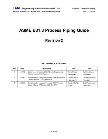
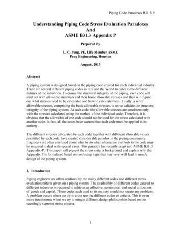
Piping Code Paradoxes B31.3 PThroughout the history of piping system design, there have been two distinctly differentdesign approaches and philosophy.In the beginning, due to the lack of accurate knowledge and calculation tools, the pipingwas designed with minimum calculations, but based on a lot of rules and experiments.This approach, though not exact, has designed a lot of successful piping systems formany decades. Therefore, it is valued and used extensively even up to this date and willcontinue to be used for many more decades to come. This is the design approach adoptedby ASME B31 Code for Pressure Piping and many other piping codes in the world.As the technology progressed and the piping got more critical, such as in the case ofnuclear piping that involves the welfare of society, engineers started looking forsomething more concrete and exact. How to be more exact? First, of course, is tocalculate all the stresses that exist in the piping accurately. Then, set up the stress criteriafor the calculated stresses to protect all conceivable modes of failure. This new approachis called “Design by Analysis,” in contrast to the “Design by Rules” adopted by B31codes.The “Design by Analysis” approach is more theoretical oriented and has theoretical basisto back it up. For this reason, engineers may be tempted to use the criteria set up for thisapproach for the stress calculated by B31. This mixed-up use of the codes is, of course,not permitted, but somehow considered valid by some engineers thinking the stresscriteria for the “Design by Analysis” must be universally applicable. This is theconfusion that has crept into Appendix P of ASME B31.3 [1]. Leaving it as-is, theAppendix P may lead to unsafe design of the piping system.Throughout this paper, we will use a typical 10” standard wall thickness long radiuselbow, as shown in Figure 1, as the example component to exam the differences andvalidities of the two approaches. The use of this example elbow provides somecomparison numbers instead of just symbols.2
Piping Code Paradoxes B31.3 P3
Piping Code Paradoxes B31.3 P2. Design by AnalysisThe Design by Analysis approach is adopted for critical piping to weed out all thepotential uncertainties to positively ensure the safety of the piping system. Since itinvolves a lot of more calculations that might substantially increase the cost and scheduleof a project, this approach is currently adopted only by ASME B&PV Section III [2] Class1 Components and Section VIII Division 2 [3] Alternative Rules for Pressure Vessels indesign of piping and pressure vessels. We will use Class 1 nuclear piping as the guide tosee what the stresses are calculated and what are the allowable values.In formulating the design requirements of this Design by Analysis approach, a specialASME review committee was created to establish the Stress Criteria [4] for protecting thepiping from potential modes of failures based on calculated stresses. These stress criteriaare summarized in Table 1. From the table, it is clear that the criteria provide the pipingwith membrane protection and fatigue protection. The loads are classified as primary (orsustained) and secondary (or self-limiting), two main categories. The definitions are alsomostly included in Table 1. The primary loads are also called non-self limiting loads. Allsustained loading (non self-limiting) at design conditions are evaluated for membraneprotection, while all repeating primary as well as secondary load ranges are all includedin fatigue evaluation. Dead weight is not included in primary plus secondary stressevaluation as it is non cyclic, but live weight such as carrying fluid is included.2.1 Membrane ProtectionBesides the standard pressure design that is comparable to all codes, the membraneprotection is checked by the following equation: (Table 1, PL which includes Pm Pb)B1PDD B 2 M i, L 1.5S m2t2I(A)Where,P Design pressureB1 Primary stress index for pressure ( 0.5 for bend ) (1983 Edition)h Flexibility characteristic ( tR/r2 for bend ) ( 0.203 for example elbow )B2 Primary stress index for moment ( 1.30/h2/3 for bend ) ( 3.76 for example elbow )2I/D Z (Section modulus)Sm Allowable stress intensity at design temperature( 2/3 Sy,h or less. Use 2/3 Sy,h for simplifying comparison)Sy,h Yield strength of the material at design temperatureMi,L Resultant moment due to combination of design mechanical loads including inertiaearthquake loads. The resultant moment is calculated from moment components in eachdirection combining all included loads in a conservative way.(See Figure 1 for dimensions)4
Piping Code Paradoxes B31.3 PFor the example elbow component, Equation (A) can be rewritten as follows:M i, LPD 3.76 1.0S y, h4tZ(for 12" Std L.R. Elbow)(AA)This will later be used to compare with the evaluation by B31 codes2.2 Fatigue ProtectionThe fatigue protection is provided by evaluating all pairs of primary plus secondary stressranges following the dot line flows in Table 1. Since the main concern is fatigue, thestresses calculated are ranges between two operating conditions. The zero load conditionis also considered as one loading condition. From Table 1, there are three items that needto be evaluated. One is the primary plus secondary stress intensity range, the second isthe thermal expansion stress intensity range, and the third is peak stress intensity range,which is used to obtain the allowable number of operating cycles from applicable fatiguecurve for each operating pair. In the process, it needs to be concerned about potentialplastic hinge that might invalidate the elastic analysis. Additional considerations andhandlings are also needed when plastic cycling or ratcheting may be present in anyoperating pair or pairs.2.2.1 Check for Plastic Hinge – Gross RatchetingThis is applicable only to piping systems, but not to vessels. Thermal expansion of apiping system may involve a fairly large movement. A few inches of movement is notuncommon in a power or process plant. This movement has the potential of behaving likea sustained load when there is an especially weak location in the system. This is thereason when designing the vessel nozzle connection, the piping loads are oftenconsidered as sustained or primary load.Within the piping system, if the thermal expansion stress intensity range at a certainlocation is greater than twice of the yield strength, then the location may become a plastichinge or produce strain follow-up. If the system has one or more plastic hinges, thecommonly used elastic analysis is invalid. Therefore, for secondary stresses, the firstthing to be checked is the following: (Table 1, Pe 3Sm)Se C 2D *M i, E 3S m2I(B)Where,Se Thermal expansion stressC2 Secondary stress index for moment ( 1.95/h2/3 for bend ) ( 5.65 for exampleelbow )Mi,E* Resultant range of moment due to thermal expansion and thermal anchormovement only.5
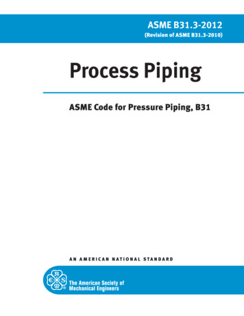
Piping Code Paradoxes B31.3 PSm Allowable stress intensity of the material at highest temperature throughout theoperation cycle involved. (To simplify comparison, use 2/3 Sy,h )For the example elbow, Equation (B) can be written as follows:Se 5.65M *i, EZ 2S y, h(for 12" Std L.R. Elbow)(BB)It is important to note that once Equation (B) is not satisfied, all the othercalculations are simply meaningless. Equation (BB) will be used later to comparewith the evaluation by B31 codes2.2.2 Check for Thermal RatchetingIf the total primary plus secondary stress intensity range, including effects ofdiscontinuity but not local stress concentration, exceeds twice the yield strength, a smallamount of plastic deformation accumulates during each cycle of operation. Thisphenomenon is called ratcheting. The primary plus secondary stress intensity range foreach operating pair is calculated by (Table1, PL Pb Pe Q )P DDS n C1 o C 2 M i, T C 3 E ab [α a Ta α b Tb ] 3S m2t2I(C)Where,C1 Secondary stress index for pressure ( (2R –r)/2(R – r) for bend )( 24.81/19.613 1.26 for example elbow )Po Range of service pressureC2 Secondary stress index for moment ( 5.65 for example elbow )Mi,T Resultant range of moment from all thermal expansion, mechanical loads, liveweight, wind and/or earthquake inertia loads, earthquake and/or wind anchordisplacement, etc. Dead weight is not included as it is not cyclic.C3 1.0 for bendEab [αaTa – αbTb ] Gross temperature discontinuity stress. E and α are based on roomtemperature.For the example elbow, Equation (C) can be written asM i, TP DS n 1.26 o 5.65 E ab [α a Ta α b Tb ] 2S y, h2tZ(for 12" Std L.R. Elbow)(CC)It is important to note that the participation of pressure in this equation is themaximum hoop stress, not the longitudinal stress as in Equation (AA). This is due tothe fact that the maximum local stress is generally in the circumferential direction,6
Piping Code Paradoxes B31.3 Pwhich is in the same direction as the pressure hoop stress. See Figure 2 for thefatigue failure location of the bend due to moment loading.The piping system may still be acceptable even if Equation (C) is not satisfied. Howeverwhen Sn 2Sy the system will have a ratcheting effect, accumulating some small plasticstrain through each cycle of operation. In this case, the evaluation will have to go throughelastic-plastic process. To simplify our discussion, we will consider only the cases whenEquation (C) is satisfied.The satisfaction of Equation (C) does not necessarily mean the fatigue protection isfulfilled. It all depends on Sn stress level and number of operating cycles of all pairs ofloading conditions. To satisfy the fatigue protection, the following peak stress intensityrange and alternating stress intensity for each pair of loading have to be calculated andevaluated.2.2.3 Peak Stress Intensity Range and Alternating Stress IntensityThe peak stress range including local notch stress concentration factor is calculated by(Table 1, PL Pb Pe Q F )P DD1S p K1C1 o K 2 C 2 M i, T K 3 Eα T1 2I2(1 µ)2t1 K 3C 3 E ab [ α a Ta α b Tb ] Eα T2 1 µ(D)Where,K1, K2, K3 are stress concentration factor of the components. All are equal to1.0 for theelbow component away from a weld.ΔT1 Effective linear temperature difference between outside and inside walls acrossthe thickness. (See Ref .2 for details)7
Piping Code Paradoxes B31.3 PΔT2 Nonlinear temperature gradient across the wall thickness that is not included inthe linearΔT1. (See Ref.2 for details)µ Poisson ratioα Thermal expansion rateWhen Equation (C) is satisfied, the alternative stress intensity is calculated as one-half ofthe peak stress. That isSalt Sp2(When S n 3S m )(E)This Salt for each operation load pair is checked with the allowable fatigue curve to obtainthe allowable number of operating cycles, NiA. This is then converted to the usage factorof the load pair as Ui Ni / NiA. Ni is the number of the operating cycles for the i-th loadpair. The total usage factor or cumulative damage for all load pairs is the sum of all theindividual load pair usage factors. The total usage factor shall be less than 1.0.The peak stress intensity range is not directly comparable to any stress calculated by B31.Therefore, no comparison will be made in this paper. It should be noted, however, thatC2K2 is closely related to twice of the stress intensification factor of B31 codes [5].3. B31 Approach – Design by RulesIn the earlier days when knowledge was not sufficient to precisely look into many stressdetails, piping systems were designed with rough calculations on basic items and a lot ofrules and experiments. The rules include details on junction shapes, design specifications,standard support details, limit on support spacings, operating
Piping Code Paradoxes B31.3 P 1 Understanding Piping Code Stress Evaluation Paradoxes And ASME B31.3 Appendix P Prepared By L. C. Peng, PE, Life Member ASME Peng Engineering, Houston August, 2013 Abstract A piping system is designed based on the piping code created for each individual industry. There are several different piping codes in U.S and the World to cater to the different natures of .