Transcription
8028 SIP DoorphoneInstallation and User GuideAlgo Communication Products Ltd., Burnaby, BC Canada V5J 5L2www.algosolutions.com-1-PN #: 90-00054C
Important Safety NoticeThe 8028 SIP Doorphone is designed and tested to comply with EN 60950-1:2006 safetyrequirements.When the Doorphone Controller is connected to wiring that exits the building, there is potentialrisk of lightning induced electrical surges or high voltages from fault conditions. To reduce risk,outdoor wiring should be protected by Earth grounded conduit whenever possible.If outdoor wiring will be connected to the Doorphone Controller then the power supply providedwith the Doorphone Controller must first be connected to a properly Earthed mains supply.Under no circumstances can the Doorphone Controller be disconnected from Earth ground whileconnected to outdoor wiring.SupportAlgo is pleased to offer telephone or email support relating to installation issues, applicationsassistance, or general product inquiries.Algo Communication Products Ltd.4500 Beedie StreetBurnaby, British ColumbiaCanada, V5J solutions.com604.454.3790Algo products are warranted against defect in workmanship for a period of 12 months afterinstallation not to exceed 18 months from date of manufacture.FCC ComplianceThis equipment has been tested and found to comply with the limits for a Class B digital device, pursuant to part 15of the FCC Rules. These limits are designed to provide reasonable protection against interference in a residentialinstallation. This equipment generates, uses, and can radiate radio frequency energy and, if not installed and usedin accordance with the instructions, may cause harmful interference to radio communications. However, thereis no guarantee that interference will not occur in a particular installation. If this equipment does cause harmfulinterference to radio or television reception, which can be determined by turning the equipment off and on, the useris encouraged to try to correct the interference by one or more of the following measures: 1) Reorient or relocatethe receiving antenna, 2) Increase the separation between the equipment and receiver, 3) Connect the equipmentinto an outlet on a circuit different from that to which the receiver is connected, or 4) Consult the dealer or anexperienced radio/TV technician for help.-2-
Table of ContentsSupport . . . . . . . . . . . . . . . . . . . . . . . . . . . . . . . . . . . . . . . . . . . . . . . . . . . . . . . . . . . . . . . . . . . . 2FCC Compliance . . . . . . . . . . . . . . . . . . . . . . . . . . . . . . . . . . . . . . . . . . . . . . . . . . . . . . . . . . . . . 2Important Safety Notice . . . . . . . . . . . . . . . . . . . . . . . . . . . . . . . . . . . . . . . . . . . . . . . . . . . . . . . . 2Introduction . . . . . . . . . . . . . . . . . . . . . . . . . . . . . . . . . . . . . . . . . . . . . . . . . . . . . . . . . . . . . . . . . . 4Features . . . . . . . . . . . . . . . . . . . . . . . . . . . . . . . . . . . . . . . . . . . . . . . . . . . . . . . . . . . . . . . . . . . 4Quick Install & Test . . . . . . . . . . . . . . . . . . . . . . . . . . . . . . . . . . . . . . . . . . . . . . . . . . . . . . . . . . . . 5Applications . . . . . . . . . . . . . . . . . . . . . . . . . . . . . . . . . . . . . . . . . . . . . . . . . . . . . . . . . . . . . . . . . . 6Typical Applications for Auxiliary Inputs and Outputs . . . . . . . . . . . . . . . . . . . . . . . . . . . . . . . . . 6Door or Gate Control Basics . . . . . . . . . . . . . . . . . . . . . . . . . . . . . . . . . . . . . . . . . . . . . . . . . . . . 8Door Release . . . . . . . . . . . . . . . . . . . . . . . . . . . . . . . . . . . . . . . . . . . . . . . . . . . . . . . . . . . . . . . 8Setup and Installation . . . . . . . . . . . . . . . . . . . . . . . . . . . . . . . . . . . . . . . . . . . . . . . . . . . . . . . . . 10Programming and Configuration . . . . . . . . . . . . . . . . . . . . . . . . . . . . . . . . . . . . . . . . . . . . . . . . 11Web Interface Control Panel . . . . . . . . . . . . . . . . . . . . . . . . . . . . . . . . . . . . . . . . . . . . . . . . . . . 11Basic Settings . . . . . . . . . . . . . . . . . . . . . . . . . . . . . . . . . . . . . . . . . . . . . . . . . . . . . . . . . . . . . . . 12SIP . . . . . . . . . . . . . . . . . . . . . . . . . . . . . . . . . . . . . . . . . . . . . . . . . . . . . . . . . . . . . . . . . . . . . . . 12Audio . . . . . . . . . . . . . . . . . . . . . . . . . . . . . . . . . . . . . . . . . . . . . . . . . . . . . . . . . . . . . . . . . . . . . 13Door Relay . . . . . . . . . . . . . . . . . . . . . . . . . . . . . . . . . . . . . . . . . . . . . . . . . . . . . . . . . . . . . . . . 14Advanced Settings . . . . . . . . . . . . . . . . . . . . . . . . . . . . . . . . . . . . . . . . . . . . . . . . . . . . . . . . . . . 16Network . . . . . . . . . . . . . . . . . . . . . . . . . . . . . . . . . . . . . . . . . . . . . . . . . . . . . . . . . . . . . . . . . . . 16Admin . . . . . . . . . . . . . . . . . . . . . . . . . . . . . . . . . . . . . . . . . . . . . . . . . . . . . . . . . . . . . . . . . . . . 18Provisioning . . . . . . . . . . . . . . . . . . . . . . . . . . . . . . . . . . . . . . . . . . . . . . . . . . . . . . . . . . . . . . . . 20Generating a Configuration File . . . . . . . . . . . . . . . . . . . . . . . . . . . . . . . . . . . . . . . . . . . . . . . . 21Call . . . . . . . . . . . . . . . . . . . . . . . . . . . . . . . . . . . . . . . . . . . . . . . . . . . . . . . . . . . . . . . . . . . . . . 22Auxilary I/O . . . . . . . . . . . . . . . . . . . . . . . . . . . . . . . . . . . . . . . . . . . . . . . . . . . . . . . . . . . . . . . . 24Security . . . . . . . . . . . . . . . . . . . . . . . . . . . . . . . . . . . . . . . . . . . . . . . . . . . . . . . . . . . . . . . . . . . 26Advanced SIP . . . . . . . . . . . . . . . . . . . . . . . . . . . . . . . . . . . . . . . . . . . . . . . . . . . . . . . . . . . . . . 27System . . . . . . . . . . . . . . . . . . . . . . . . . . . . . . . . . . . . . . . . . . . . . . . . . . . . . . . . . . . . . . . . . . . . . 29Maintenance . . . . . . . . . . . . . . . . . . . . . . . . . . . . . . . . . . . . . . . . . . . . . . . . . . . . . . . . . . . . . . . 29Upgrade Firmware . . . . . . . . . . . . . . . . . . . . . . . . . . . . . . . . . . . . . . . . . . . . . . . . . . . . . . . . . . . 30System Log . . . . . . . . . . . . . . . . . . . . . . . . . . . . . . . . . . . . . . . . . . . . . . . . . . . . . . . . . . . . . . . . 31LED Lights . . . . . . . . . . . . . . . . . . . . . . . . . . . . . . . . . . . . . . . . . . . . . . . . . . . . . . . . . . . . . . . . . . 31Connections and Lights . . . . . . . . . . . . . . . . . . . . . . . . . . . . . . . . . . . . . . . . . . . . . . . . . . . . . . . 32Connection Details . . . . . . . . . . . . . . . . . . . . . . . . . . . . . . . . . . . . . . . . . . . . . . . . . . . . . . . . . . 32Auxiliary Dry Contact Outputs . . . . . . . . . . . . . . . . . . . . . . . . . . . . . . . . . . . . . . . . . . . . . . . . . . 33Auxiliary Dry Contact Inputs . . . . . . . . . . . . . . . . . . . . . . . . . . . . . . . . . . . . . . . . . . . . . . . . . . . 33Specifications . . . . . . . . . . . . . . . . . . . . . . . . . . . . . . . . . . . . . . . . . . . . . . . . . . . . . . . . . . . . . . . 34-3-
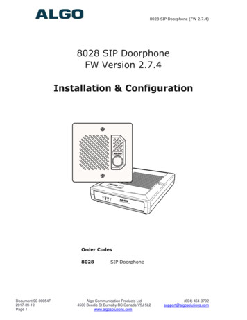
IntroductionIdeal for secure business entrances, emergency intercom, and residentialgates, Algo’s 8028 SIP Doorphoneprovides hands-free intercomcapability, entrance security with doorunlock control, rugged weatherproofdesign, and superior audioperformance.Fully compatible with SIP industrystandards, the 8028 SIP Doorphonewill work with most hosted orenterprise SIP-based serverssupporting third-party SIP endpoints.The 8028 Doorphone includes aControl Unit, Door Station, andPower Supply. The Control Unit and Door Station can be connected with asingle twisted pair wire up to 1,000 feet (300 m) with the Door Station locatedoutdoors and the Control Unit in a dry indoor location.Features Suitable for commercial or residential applications Door Station connected by a single twisted wire pair Full duplex capable hands-free voice communication at the Door Station Door control relay contacts and available 24 Vdc 0.3 A strike power Auxiliary dry contact inputs and outputs from Doorphone Controller andDoor Station Programmable via Web Interface International 110/220 V, 50/60 Hz switching power supply Regulatory: CSA/UL, FCC Class B, CE, EN60950-1 2006 CB Scheme-4-
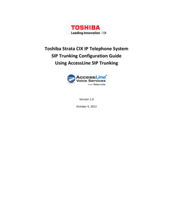
Quick Install & TestThe 8028 SIP Doorphone requires minimal configuration for a typicalinstallation. Programming is only required to enter the SIP account details, andfor more advanced applications.1. Connect the power supply to thePower Jack of the DoorphoneController and plug into anavailable AC outlet.SIP Server2. Flush or surface-mount the DigitalDoor Station at desired locationand connect a twisted telephonewire pair between the “CTRL”terminals of the Door Station andthe center pair (red and green)of the supplied Telephone WiringJack. Polarity is not important.3.Using the short six conductormodular cable, connect theTelephone Wiring Jack to the DoorStation Jack of the DoorphoneController.4. Using an Ethernet cable, connect the Ethernet Jack of the DoorphoneController to your LAN.5. Press the Call Button on the Door Station. A recorded voice will speak theIP Address of the device. Enter this address in a PC web browser in orderto open the Web Interface. Note: The spoken IP address feature will beautomatically disabled after a SIP Server is configured in Step 6 (below).6. Use the Web Interface to enter the SIP Proxy Server address as well asthe user account and password that the 8028 SIP Doorphone will use toregister. Also enter the target extension that the Doorphone will call.7. Press the Call Button on the Door Station, then answer to communicatewith the Door Station. Press the digit 6 on the phone keypad to activate thedoor control relay for three seconds (if applicable).-5-
ApplicationsTypical Applications for Auxiliary Inputs and OutputsThe 8028 architecture and digital link between the Door Station and Controllerprovides flexible options using the auxiliary inputs and outputs. These aresome typical applications:Cancel Ring When Door OpenedIn a residential or warehouse installation it is not uncommon for the door to beanswered in person before the phone is answered. Either Door Station or Control Unitinputs can be configured to cancel ring if the door is opened before a call is answered.This requires a normally closed or normally open contact to detect door open.Trigger Door Bell from Door StationWhen the Door Station call button is pressed, either (or both) the Door Station orControl Unit dry contact output can be configured to activate a door bell or auxiliaryalerting system in addition to phone ring.Trigger Door Station from External Button/EventEither the Control Unit or Door Station can accept a dry contact closure to activate theDoorphone as if the call button had been pressed. This could be an external doorbellbutton, PIR detector, or some other system.Cancel Door Open Relay once Door OpenedThe door opening control can be set for activation (using the ‘Open Code’) up to 30seconds (set by the ‘Relay Time’ setting) to allow sufficient time for entry. For security,the 8028 Doorphone can be configured to cancel Door Opening once the door isopened to prevent “tailgating” by unauthorized personnel.Unlock Door Indefinitely until CanceledThe door opening control can be set to unlock indefinitely (using the ‘Latch OpenCode’) until canceled (using the ‘Release Code’) that locks it again. This allows anentrance to be used repeatedly for a period of time without requiring multiple activationsof the door control relay.-6-
Anti-Door TamperA feature of the 8028 Doorphone is to ring the telephone(s) with a warning alert inthe event a door is ajar due to tampering (such as a door blocked open after beinglegitimately released for a visitor).In-Use and RingEither the Control Unit or Door Station can be configured to provide a dry contact outputduring ring or in-use for channel selection (typically) of third party video monitoringsystems.-7-
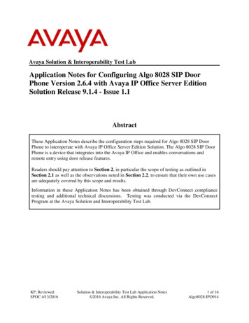
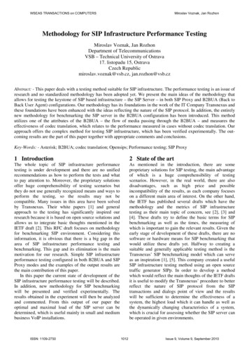
Door or Gate Control BasicsControl contacts are provided from the Doorphone Controller and are typicallyused for door strike activation or gate control. For security, the door controlrelay is located in the Controller to avoid entry by tampering. The Door Stationdry contact output (OUT) may be configured for ‘low security’ gate controlrequiring a low current dry contact.Door ReleaseDoor release typically involves energizing or de-energizing a door strike whichpivots to allow a locked door to open without retraction of the latch bolt. Thereare two different types of door strikes: “Fail Locked” (or “Fail Secure”) “Fail Unlocked” (or “Fail Safe”)Fail Locked / Fail Secure Electric StrikeThese require power to release andremain locked during power failure. Thedoor may still normally be opened fromthe outside with a key, or from insidewithout a key. The door control relay isused to apply power to release the door.Fail Unlocked / Fail Safe Electric StrikeThese (as well as magnetic locks),require power to lock and becomeunlocked during power failure. The doorcontrol relay is used to maintain powerto the door lock (NC and C contacts)which is interrupted to release the door.Magnetic locks may require overridesystems to allow safety exit in the eventof fire.-8-24V 0.3ADoorStrike“Fail Locked”24 Vdc 0.2 A Typical24V 0.3A“Fail Unlocked”24 Vdc 0.2 A Typical
Power SupplyThe Doorphone Controller provides an auxiliary 24 V 0.3 A power supply whichis suitable for common types of door strikes. If more current or a differentvoltage is required, then the customer must provide a matching power supplyfor the electric strike or magnetic lock. Maximum switching capability of thedoor control contacts is 1 A 30 V.The Door Control relay may also be configured for alternate functionalityincluding In-Use, Ring, and Call Button Press.For more information on applications for the 8028 SIP Doorphone, please visitwww.algosolutions.com/8028. The 8028 Doorphone firmware may be modified through theweb interface and Algo routinely accepts requests for custom firmware for unique applications.-9-
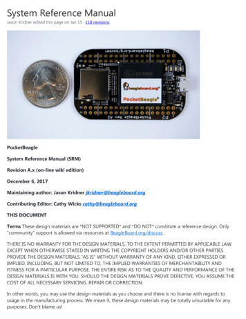
Setup and InstallationMax 1000 feet (300m)- 10 -
Programming and ConfigurationConnection to Network and Obtaining IP AddressAfter connecting the 8028 to a network port, watch for the PWR light to startwinking (on and blinking off) during initialization. The 8028 will then attemptto obtain an IP address from the DHCP server. If unsuccessful, the 8028 willdefault to the fixed IP address 192.168.1.111.To find the IP address of the 8028, press the Call Button on the Door Station.The 8028 will speak its IP address if it has not yet been configured with a SIPServer address. Alternatively, search the network using the 8028 Locator Toolavailable for download from www.algosolutions.com/8028locator.Web Interface Control PanelThe 8028 is programmed using a web interface tool accessed by entering the8028 IP address into a browser. Using this interface, you can configure the8028 network settings and select the desired options. These settings survivepower cycling and may be programmed in advance prior to site installation.- 11 -
Basic SettingsSIPSIP Domain/ProxySIP Server Name or IP addressExtensionThe phone number that the 8028 registers with the SIP Server. Itwill auto-answer any inbound calls.Auth IDAuthentication ID; Used to register the device on the SIP Server.PasswordSIP password used to register the device on the SIP Server.DialingExtensionPhone number to be dialed when the Call button on the doorstation is pressed.- 12 -
AudioSpeaker Volume Speaker audio level in 3 dB steps (Default: 8)MicrophoneVolumeMicrophone audio level in 3 dB steps (Default: 7)Ringback ToneAllows audible ringback tone to be played on Door Stationspeaker until call is answered Enabled (Default) Disabled- 13 -
Door Relay Settings- 14 -
MomentaryOpen Code1-4 digit DTMF code that can be used to unlock the door for abrief period of time (as set by the Relay Time field). Leave thisfield blank to disable this feature. (Default: 6)DurationThe duration for which to unlock the door when the MomentaryOpen Code is entered.Cancel if DoorOpenedCancels the door unlock (i.e. locks the door again) if the doorhas been opened to ensure it cannot be opened a 2nd time. Onlyavailable if the controller input or door station is configured forDoor Sensor mode.Latch OpenCode1-4 digit DTMF code that can be used to unlock the doorindefinitely. Leave this field blank to disable this feature.Latch ClosedCode1-4 digit DTMF code that will lock the door again when it islatched open. Leave this field blank to disable this feature.DTMF DetectionTypeUse the default of ‘Auto’ unless advised by Algo technical support.Allow NetworkControlAllows auxilary relay control by network command. Contactsupport for more information.- 15 -
Advanced SettingsNetwork- 16 -
ProtocolDHCP is an IP standard designed to make administration of IPaddresses simpler. When selected, DHCP will automaticallyconfigure IP addresses for each 8028 on the network. Alternativelythe 8028 can be set to a static IP address.VLAN ModeEnables or Disables VLAN Tagging. VLAN Tagging is thenetworking standard that supports Virtual LANs (VLANs) onan Ethernet network. The standard defines a system of VLANtagging for Ethernet frames and the accompanying proceduresto be used by bridges and switches in handling such frames.The standard also provides provisions for a quality of serviceprioritization scheme commonly known as IEEE 802.1p anddefines the Generic Attribute Registration Protocol.VLAN IDSpecifies the VLAN to which the Ethernet frame belongs. A 12-bitfield specifying the VLAN to which the Ethernet frame belongs.The hexadecimal values of 0x000 and 0xFFF are reserved.All other values may be used as VLAN identifiers, allowing upto 4094 VLANs. The reserved value 0x000 indicates that theframe does not belong to any VLAN; in this case, the 802.1Q tagspecifies only a priority and is referred to as a priority tag. Onbridges, VLAN 1 (the default VLAN ID) is often reserved for amanagement VLAN; this is vendor specific.VLAN PrioritySets the frame priority level. Otherwise known as Priority CodePoint (PCP), VLAN Priority is a 3-bit field which refers to theIEEE 802.1p priority. It indicates the frame priority level. Valuesare from 0 (lowest) to 7 (highest). These values can be used toprioritize different classes of traffic (voice, video, data, etc).SIP (6-bit DSCPvalue)Can provide quality of service if the DSCP protocol is supportedon your network. Can be specified independently for SIP controlRTP (6-bit DSCP packets versus RTP audio packets.value)DHCP Timeout(seconds)Length of time following a request from an 8028 to the DHCPserver that the 8028 will wait before assuming the server is notavailable. After such time, the 8028 will use its default address of192.168.1.111Default is 60 seconds.- 17 -
Admin- 18 -
PasswordPassword to log into the 8028 web interface.You should change the default password in order to secure thedevice on the network. If you have forgotten your password, a softreset will restore the default setting (including all of the device’sdefault settings). To do this, first disconnect power from the 8028Doorphone Controller. Then press and hold the Reset button onthe back of the device, and while doing this, reconnect the power.Continue to hold the Reset button until the LEDs on the front ofthe controller start to flash.ConfirmationRe-enter password to log into 8028 web interface.Device NameName to identify the device in the Algo Network Device LocatorTool.NTP TimeServerAllows the 8028 to synchronize to an external time server.IntroductionSection onStatus PageAllows the introduction text to be hidden from the login screen.Log LevelAmount of information provided in the log files. This value shouldonly be changed if advised by Algo.Log SizeAmount of internal memory reserved for recording log file. Defaultis 100 kB.Log MethodSets storage location of log file data. Default setting is Local.Choose Network (or Both) to send log messages to any “Syslog”server, an option to prevent loss of data during a powerdown.HardwareWatchdogUse on the advice of Algo technical support only.SNMP Support(v1 get only)Additional SNMP support is anticipated for future, but the 8028now responds to a simple status query for automated supervision.Contact Algo technical support for more information.- 19 -
ProvisioningProvisioning allows installers to pre-configure 8028 units prior to installation on anetwork. It is typically used for large deployments to save time and ensure consistentsetups.There are two different Provisioning methods that can be used: via DHCP Option 66 orvia a Static Server. In addition, there are three different ways to download provisioningfiles from a “Provisioning Server”: TFTP (Trivial File Transfer Protocol), FTP, or HTTP.For example, 8028 configuration files can be automatically downloaded from a TFTPserver using DHCP Option 66. This option code (when set) supplies a TFTP boot serveraddress to the DHCP client to boot from.DHCP must be enabled if using DHCP Option 66, in order for Provisioning to work.One of two files can be uploaded on the Provisioning Server (for access via TFTP, FTP,or HTTP):1. generic file algop8028.conf, or2. specific file algom[MAC].conf- 20 -
MD5 ChecksumIn addition to the .conf file, an .md5 checksum file must also be uploaded to the Provisioningserver. This checksum file is used to verify that the .conf file is transferred correctly without error.A tool such as can be found at the website address below may be used to generate this file.http://www.fourmilab.ch/md5The application doesn’t need an installation. To use the tool, simply unzip and run the application(md5) from a command prompt. The proper .md5 file will be generated in the same directory.If using the above tool, be sure to use the “-l” parameter to generate lower case letters.Generating a generic configuration file1.Connect an 8028 on the network2.Access the 8028 Web Interface Control Panel3.Configure the 8028 with desired options4.Click on the System tab and then Maintenance.5.Click “Backup” to download the current configuration file6.Save the file settings.txt7.Rename file settings.txt to algop8028.conf8.File algop8028.conf can now be uploaded onto the Provisioning server- 21 -
If using a generic configuration file, extensions and credentials have to be entered manuallyonce the 8028 has automatically downloaded the configuration file.Generating a specific configuration file1.Follow steps 1 to 6 as listed in the section “Generating a generic configuration file” on page21.2.Rename file settings.txt to algom[MAC address].conf(e.g. algom0022EE020009.conf)3.File algom[MAC address].conf can now be uploaded on the Provisioning server.The specific configuration file will only be downloaded by the 8028 with the MAC addressspecified in the configuration file name. Since all the necessary settings can be included in thisfile, the 8028 will be ready to work immediately after the configuration file is downloaded. TheMAC address of each 8028 can be found on the back label of the unit.Call- 22 -
AnswerInbound CallAuto-answer or ignore inbound calls Enabled (Default) DisabledAnswer ToneAn optional beep tone can be played at the Door Station when itanswers an inbound call Enabled (Default) DisabledOutbound RingLimitCancel dial attempt if call is not answered within specific duration. No ring Limit to 1-9 rings (Default: 5 Rings) No limitCancel if DoorOpenedCancel dial attempt if door has been opened before call isanswered. Only available if the controller input or door stationinput is configured for Door Sensor mode, and a physical sensoris available at the door. No (Default) YesAllow CallButtonto End CallIf enabled, allows visitor to end an active call by pressing the CallButton. Enabled Disabled (Default)Maximum CallDurationSelect the maximum call duration before the call will beterminated- 23 -
Auxiliary I/O- 24 -
Controller andDoor StationOutput Options In-Use (Default)DialCall Button PressDoor ControlDoor SensorDoor Alarm Follow Controller Input Follow Station Input DisabledDoor Relay In-UseDialCall Button PressDoor Control (Default)Door Sensor In-UseDefinition Call Connected: Active from call answer to end of session Call Ringing or Connected: Active from button press to end ofsessionController Input Door Sensor, Normally Open InputDoor Sensor, Normally Closed Input (Default)Manual Door Release InputDoor Control Lockout InputCall Button, Normally Open InputCall Button, Normally Closed InputDisabledDoor StationInput Door Sensor, Normally Open InputDoor Sensor, Normally Closed InputCall Button, Normally Open Input (Default)Call Button, Normally Closed InputDisabled- 25 -Door AlarmFollow Controller InputFollow Station InputDisabled
SecurityMax Door OpenIf the Controller or Door Station input is connected to a physicaldoor sensor and also configured in Door Sensor mode (See“Auxiliary I/O Settings” on page 31), then a Door Alarmcondition can be triggered if the door remains open for longerthan a threshold of: 30 sec 60 min 90 min 2 min 15 min 120 min 30 min NoneDoor OpenAlarmWhen a Door Alarm condition is detected based on the Max DoorOpen time above being exceeded, then the 8028 can generate anotification call.Call every: 2 min (Default) 10 min 30 minDoor StationDisconnected 1 hour NoneIf a wiring fault occurs that breaks communication with the DoorStation, then the 8028 can generate a notification call.Call every: 2 min 10 min 30 min 1 hour None (Default)- 26 -
Advanced SIP- 27 -
OutboundProxyIP address for outbound proxy. A proxy (server) stands between aprivate network and the internet.STUN ServerIP address for STUN server if present.Register Period(seconds)Maximum requested period of time where the 8028 will re-registerwith the SIP server. Default setting is 3600 seconds (1 hour). Onlychange if instructed otherwise.Keep-aliveMethodIf Double CRLF is selected the 8028 will send a packet every 30seconds (unless changed) to maintain connection with the SIPServer if behind NAT.ServerRedundancyFeatureTwo secondary SIP servers may be configured. The 8028will attempt to register with the primary server but switch to asecondary server when necessary. The configuration allows reregistration to the primary server upon availability or to stay with aserver until unresponsive.Backup Server#1If primary server is unreachable the 8028 will attempt to registerwith the backup servers. If enabled the 8028 will always attemptto register with the highest priority server.Backup Server#2Polling Interval(seconds)Time period between sending monitoring packets to each server.Non-active servers are always polled, and active server mayoptionally be polled (see below).Poll ActiveServerExplicitly poll current server to monitor availability. May also behandled automatically by other regular events, so can be disabledto reduce network traffic.AutomaticFailbackReconnect with higher priority server once available, even ifbackup connection still fine.Polling MethodSIP message used to poll servers to monitor availability.- 28 -
SystemMaintenanceDownloadConfigurationFileSave the device settings to a text file for backup or to setup aprovisioning configuration file.RestoreConfigurationFileRestore settings from a backup file.RestoreConfigurationto DefaultsResets all 8028 device settings to factory default values.Reboot theDeviceReboots the device.Firmware Image This is the firmware image and checksum as provided by AlgoMD5 Checksum- 29 -
Upgrade 8028 Firmware1.From the top menu, click on System, then Maintenance.2.In the Maintenance section, click RebootWait 30-60 seconds for the device to reboot and the web page to automaticallyreload.3.Login to the device again, and click on System.4.In the Upgrade section, click on Choose File and select the 8028 firmware file toupload. Note that both the FW firmware and MD5 checksum files must be loaded.5.Click Upgrade6.After the upgrade is complete, confirm that the firmware version has changed (referto top right of Control Panel).- 30 -
System LogPart 1Part 2Use on the advice of Algo technical support only.View AllLED DetailsPower On steady: Power is OK, but Ethernet Link not established Blinks one second on, one second off: Ethernet Link statusOK, but IP Address not yet obtained Light on, blinks off briefly every two seconds: Link and IPAddress established successfullyTelephone Off - Not registered with SIP server Light on, blinks off briefly every two seconds: Successfullyregistered with SIP Server, ready for use Blinks one second on, one second off: error registering withSIP Server – check configuration On steady: offhook or ringing state is currently activeDoorStation On steady when door station is connected Flashing indicates communication errorsLock On when Door Relay is activated- 31 -
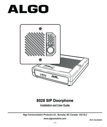
Connection DetailsDoor ControlRelay5 Position RemovableTerminal BlockAuxiliaryPowerDoor Station JackRJ12 Telephone JackEthernet JackRJ45 JackNONormally OpenCCommonNCNormally ClosedPWR -0.3 A (GND)PWR 0.3 A (24 V)Center Pair (Red &Green)Door StationMiddle Pair(Yellow & Black)Dry Contact InputMax 1 kΩOutside Pair(Blue & White)Dry Contact OutputMax 50 mA 30 V24V 0.3AConnect to LAN with access toSIP-compliant Proxy ServerReset ButtonTo return all settings to a factory default,press and hold the reset button at startup.Continue to hold the button until all LEDsstart to flash.Door StationCTRLConnect to Door Station J
The 8028 SIP Doorphone is designed and tested to comply with EN 60950-1:2006 safety . Algo's 8028 SIP Doorphone provides hands-free intercom capability, entrance security with door . Press the digit 6 on the phone keypad to activate the door control relay for three seconds (if applicable). - 6 -