Transcription
International Journal of Engineering Research & Technology (IJERT)ISSN: 2278-0181Vol. 3 Issue 6, June - 2014Flexibility and Stress Analysis of Piping Systemusing CAESAR II- Case StudyMs. Prachi N. TambeProf. Dr. K. K.DhandeMechanical Engineering DepartmentDYPIETPune, IndiaMechanical Engineering DepartmentDYPIETPune,IndiaProf. N. I. JamadarMechanical Engineering Department DYPIETPune, IndiaAbstract— Process Plant can be operated safely and is study is emphasis on the process piping code ASME B31.3. As the piping temperature changes from installationcondition to operating condition, it expands or contracts. Bothexpansion and contraction is known as thermal expansion.When a system tries to expand in a rigid piping system, a largeamount of stresses are generated leading to failure of system.Flexibility analysis plays a major role in designing the pipingsystem. Flexibility analysis is a part of stress analysis. Stressanalysis of piping system is performed to verify thecompliance with the Design Code, to calculate pressure vesselnozzle loads, displacements due to thermal expansion,selection of support type and support location on pipingsystem etc. The aim of this study is to analyze the stresses inthe piping system.IJERTwith the help of good design of equipments and piping systemsconnecting to the various equipments like tanks, heat exchangers,pumps etc. Design of piping system includes the pipe and fittingsizing, thickness calculation, equipment layout, pipe routing,support type, support location finalization and stress analysis.This study explains the stress analysis of piping system as perprocess piping code ASME B 31.3 using 3D software toolCAESAR II. Major requirements in piping stress analysis are toprovide adequate flexibility for absorbing thermal expansion,code compliance for stresses incurred in piping system, safenozzle loads and displacement. The design is said to be safe if alltheseareinallowablerangeaspercode.In this study, the criterion of selection of piping system forflexibility analysis is explained analytically. The two pipingsystems are stress analyzed, compared and the effect of flexibilityof piping system on nozzle loads and stresses developed areobserved. The software output is discussed and safer pipingsystem is identified.Keywords— Code compliance, Nozzle Loads, PipingFlexibility, Stress Analysis, ,I.INTRODUCTIONPiping system is the heart of any process plant. Theperformance of the plant depends on the pipe line sizing,Equipment layout, Pipe routing with minimum possiblepressure drop, considering all mechanical and operationalsafety.Piping system comprises of pipes, fittings like elbows, tees,reducers, sockets, half couplings, unions, flanges and valves.These all are used to transfer the fluid from one point toanother through straight pipes, changing the direction withmost economical means- elbow [11], branching through tees,II.PIPE LAYOUT AND ROUTINGFlexibility of piping system is mainly dependent on theEquipment Layout. While finalizing the location ofequipments, the connecting piping flexibility is also to beconsidered alongwith the process flow, accessibility to valves,instruments, equipment maintenance, cleaning, operationalsafety, headroom clearance and aesthetics. The piping layoutdesigner has to undergo number of iterations to reach to a finallayout. Pipe Routing is always decided based on theEquipment layout. The best possible pipe routing is achievedby knowing the process flow and the above criterion forlayout.Pipe Data:Pipe Size: DN 200Pipe Schedule: Sch 5SPipe Material: A312 TP 316LMax. Operating temperature: 1100cMax. Operating Pressure: 1.5 bar (g)Fluid density: 1100 kg/m3Ambient Temperature: 250csize variation through reducers or reducing tee at branches,connecting each other or to the instruments through flanges,union, sockets, half couplings and on-off conditions or fluidIJERTV3IS060582www.ijert.org370
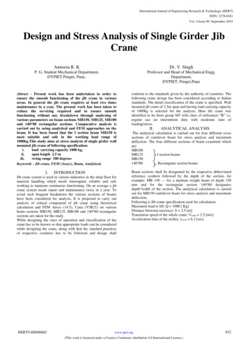
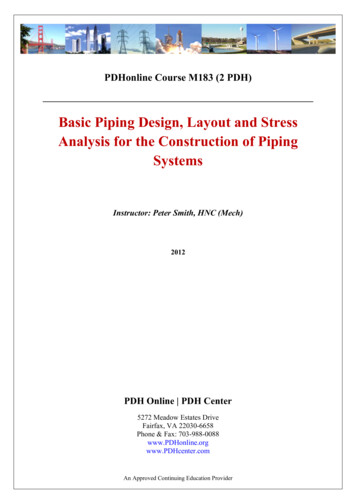
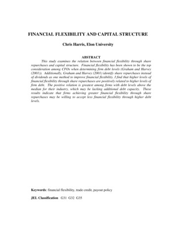
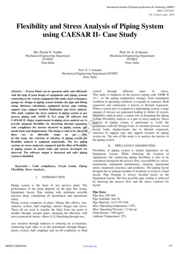
International Journal of Engineering Research & Technology (IJERT)ISSN: 2278-0181Vol. 3 Issue 6, June - 2014Ea Reference Modulus of Elasticity at 210c in MPa (ksi)SA Allowable displacement stress Range in MPa (ksi)Sc Allowable stress at cold operating temp. in MPa (ksi)Sh Allowable stress at hot operating temp. in MPa (ksi)For the piping system I, calculated value of k1 ((D x y)/ (L-u)2) 2.21k1 30 x SA/ Ea (in. / ft2)Sc for 40oc 16.7 ksi (As per Table A-1 Basic Allowablestresses in Tension for metals- for A312-TP 316L)Sh for 110oc 16.7 ksi (As per Table A-1 Basic Allowablestresses in Tension for metals- for A312-TP 316L)Allowable Stress Range SA f (1.25 Sc 0.25 Sh)f 1 for 104 cycles (Table 302.3.5 Stress Range Factor,f)SA 1((1.25x16.7) (0.25x16.7)) 25.05 ksiEa Reference modulus of elasticity at 210c (700F) 28.3 x10³ ksi (Table C-6- Modulus of Elasticity for metals- ForAustenitic steels)k1 30 x SA/ Ea (in. / ft2)Limiting value of k1 ((D x y)/ (L-u)2) 0.027Fig: 1- 3D view of piping System 1 to be designedIV.STRESS ANALYSIS 3D MODELLINGIJERTPiping stress analysis is a term applied to calculations, whichaddress the static and dynamic loading resulting from theeffects of gravity, temperature changes, internal and externalpressures. The purpose of stress analysis is to ensure safety ofpiping and piping components as well as the safety ofconnected equipments and supporting structure [7]Flexibility as well as stress analysis for this piping system isdone through CAESAR II software.Operating loads are calculated using self weight, operatingpressure and temperature for the piping system, Sustainedloads are by using self weight and operating pressure andExpansion loads are due to temperature differences.Fig. 2- Isometric view of piping system 1 to be designedIII.FLEXIBILITY ANALYSIS CRITERIONOnce the piping layout is fixed, the nearest possible routing ofpiping system is done.As per ASME B 31.3 [2], No formal analysis of adequateflexibility is required for a piping system whicha) Duplicates or replaces without significant change, a systemoperating with successful service record.b) Can readily be judged adequate by comparison withpreviously analyzed systemsc) is of uniform size, has no more than two points of fixation,no intermediate restraints, and falls within the limitation ofempirical equation:((D x y)/ (L-u)2) k1(1)Where,D outside diameter of pipe in mm (inch)y Resultant of total displacement strains in mm (inch), to beabsorbed by the piping systemL developed length of piping between anchors in m (ft)u anchor distance, straight line between anchors, in m (ft)k1 208000 x SA/ Ea (mm/m2) or 30 x SA/ Ea (in. / ft2)IJERTV3IS060582www.ijert.orgFig. 3- Modeled piping system 1 in CAESAR II software371
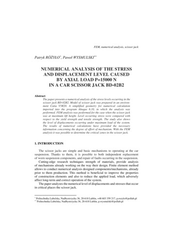
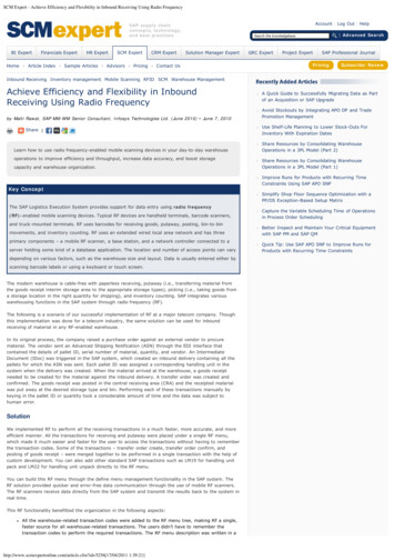
International Journal of Engineering Research & Technology (IJERT)ISSN: 2278-0181Vol. 3 Issue 6, June - 20141: Code compliance and Nozzle loading for piping systemIJERTTable 1- Nozzle Load on Tanks for the piping system 1 to be designed- CAESAR outputTable 2- Nozzle Load on Tanks for the modified piping system 2 - CAESAR outputAnother piping system with same size and same operatingpressure and temperature connecting with the sameequipments can be routed as follows, as the equipment layoutis different.IJERTV3IS060582www.ijert.org372
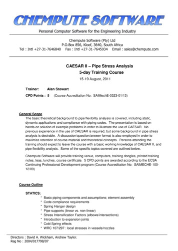
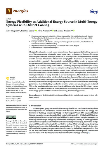
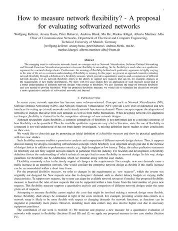
International Journal of Engineering Research & Technology (IJERT)ISSN: 2278-0181Vol. 3 Issue 6, June - 20142: Code compliance and Nozzle loading for piping systemThe reports for code compliance and nozzle loads fromCAESAR II software are generated.Calculated value of k1 ((D x y)/ (L-u)2) for piping system 2 is0.025V.Fig. 4- Isometric view of piping system 2 to be designedRESULTSIJERTPiping flexibility empirical equation is solved for the pipingsystems to be designed. The values found for k1 are 2.21 and0.025 for piping system 1 and Piping system 2 respectively.The limiting value calculated for the mentioned pipe data is0.027.CAESAR II output for Piping system 1 and Piping system 2 isobserved. Code compliance evaluation for both the pipingsystems is passed i.e. the maximum stresses developed in thepiping systems is less than the allowable stress mentioned bythe process piping code ASME B 31.3. The code stress ratio is6.3% for piping system 1 and 34.6% for piping system 2.Fig. 5- Modeled piping system 2 in CAESAR II softwareTable 3-Maximum nozzle loads on the connecting tanks at Node No. 10 and 110 for piping systemsPiping System 1Node No. 10Node No. 110Fx (lb)-2062420624Fy (lb)2397-2673Fz (lb)0-0Mx (lb.ft)-0-0My (lb.ft)-00Mz (lb.ft)8541.427834.6Piping System 2Node No. 10Node No. 110Fx (lb)-734734Fy (lb)413-724Fz (lb)-847847Mx (lb.ft)-625.11966.7My (lb.ft)3777.0-1571.8Mz 3
International Journal of Engineering Research & Technology (IJERT)ISSN: 2278-0181Vol. 3 Issue 6, June - 2014VI.CONCLUSIONVIII. REFERENCESThe analytical study of piping systems is done using theprocess piping code ASME B 31.3 and 3D software toolCAESAR II is used for piping system modeling and stressanalysis purpose. The analytical and software output isobserved. The flexibility analysis requirement for the pipingsystem is checked analytically using the design code ASME B31.3 and also the system is stress analyzed using CAESAR IIsoftware. The results are analyzed and found thati) Piping system 2 is safer than the Piping system 1.ii) Piping system 2 is more flexible than the piping system TThe flexibility, code compliance and Nozzle loads onconnecting equipments are observed. The empirical equationlimiting factor (k1) for the pipe design data provided is 0.027.Analytically, for piping system 1, the observed factor is 2.21which is beyond the limiting factor. So flexibility analysis forpiping system 1 is must. While for piping system 2, theobserved factor is 0.025 which is less than the limiting value.So, flexibility analysis for piping system 2 is not requiredanalytically.When the software output is observed for these systems, thenozzle load force in X direction (Fx) and moment in Zdirection (Mz) for piping system 1 are very high as comparedto allowable nozzle loads. This may lead to failure of thesystem at nozzles (Node No. 10 and 110).To avoid the failure,either the equipment thickness is to be increased or somereinforcement has to be provided at nozzle, depending on theseverity of nozzle loads developed. This increases the cost ofthe system which is not acceptable. But the nozzle loads forthe piping system 2 are within the allowable loads onequipment.The stresses developed in both the pipe system are in codestress limit and hence can be accepted.“ASME Section II, Div. 1” 2007 Edition“ASME B 31.3” 2008 Edition- American Society of MechanicalEngineers Process piping codeA. R. Veerappan and S. Shanmugan, 2011, “Correlation between pipebend geometry and allowable pressure in pipe bends using ArtificialNeural Network”, International Journal of Engineering, Science andTechnology, Vol. 3, No. 4, pp. 284-296C Basavaraju, William Saifung Sun- “Stress Analysis of PipingSystems”, Edition 2004, Published by McGraw Hill, pp. B107-B120Gaurav Bhende and Girish Tembhare, 2013,”Stress Intensification andFlexibility in Pipe Stress Analysis" -International Journal of ModernEngineering Research, (IJMER) Vol-3, Issue-3, pp. 1324-1329Jaroslav Mackerle, “Finite Elements in the Analysis of Pressure Vesseland Piping, an addendum: abibliography (2001-2004)”, 2004,International Journal of Pressure Vessel and Piping, vol. 82, pp. 571-592Jelena Priss, Ivan Klevtsov, 2011, “The Programs for StrengthCalculation in Pipelines”, 10th International Symposium “10th TropicalProblems in the field of Electrical and Power Engineering”, Jan10-15,pp. 209-212[6] N.A. Alang, N. A. Razaq and A. S. Sulaiman, 2011, “Determinationof Burst Pressure of API steel pipes using Stress Modified Critical StrainModel”, International conference on Mechanical Engineering Research(ICMER 2011)N Thiagarajan, 2013, “Estimation of Pipe, Elbow and anchor loads dueto Internal Pressure”, International Journal of Engineering andInnovative Technology, (IJEIT) Vol-2, Issue-7, pp. 314-317P.M. Gedkar and Dr. D. V. Bhope, 2012, “Finite Element Analysis ofPipe T-Joint”, International Journal of Engineering, Science andTechnology (IJEST), Vol-4, No.-1, pp. 163-169T. Christo Michael, AR. Veerappan, S.S. Shanmugam, 2011, “Effect ofcross section on collapse load in pipe bends subjected to in-plane closingmoment”, International Journal of science and Technology, Vol.-3, No.6, pp 247-256T V V Satyanarayana, V Sreenivasulu, Dr. C Udaya Kiran, “Modelingand Sress Analysis of Flare Piping”, International Journal of LatestTrends and Technology, (IJLTET), vol. 2, issue 1, pp. 219-225J. Clerk Maxwell, A Treatise on Electricity and Magnetism, 3rd ed., vol.2. Oxford: Clarendon, 1892, pp.68-73.I.S. Jacobs and C.P. Bean, “Fine particles, thin films and exchangeanisotropy,” in Magnetism, vol. III, G.T. Rado and H. Suhl, Eds. NewYork: Academic, 1963, pp. 271-350.K. Elissa, “Title of paper if known,” unpublished.R. Nicole, “Title of paper with only first word capitalized,” J. NameStand. Abbrev., in press.Y. Yorozu, M. Hirano, K. Oka, and Y. Tagawa, “Electron spectroscopystudies on magneto-optical media and plastic substrate interface,” IEEETransl. J. Magn. Japan, vol. 2, pp. 740-741, August 1987 [Digests 9thAnnual Conf. Magnetics Japan, p. 301, 1982].M. Young, The Technical Writer’s Handbook. Mill Valley, CA:University Science, 1989.This study reveals that more the flexibility, lesser are thenozzle loads on the equipments. Hence the piping system 2 ispreferred to piping system ww.ijert.org374
CAESAR II is used for piping system modeling and stress analysis purpose. The analytical and software output is observed. The flexibility analysis requirement for the piping system is checked analytically using the design code ASME B 31.3 and also the system is stress analyzed using CAESAR II software. The results are analyzed and found that i) Piping system 2 is safer than the Piping system 1 .