Transcription
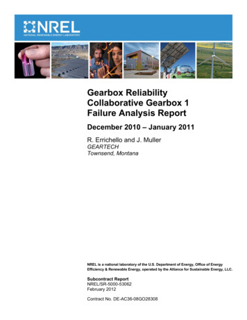
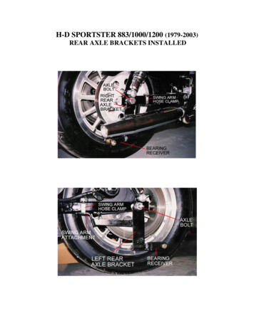
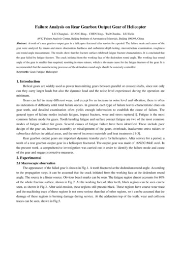
Failure Analysis on Rear Gearbox Output Gear of HelicopterLIU Changkui,ZHANG Bing,CHEN Xing,TAO Chunhu,LIU DelinAVIC Failure Analysis Center, Beijing Institute of Aeronautical Materials, Beijing 100095, ChinaAbstract: A tooth of a rear gearbox output gear in a helicopter fractured after service for a period. The failure mode and causes of thegear were analyzed by macro and micro observation, hardness and carburized depth testing, microstructure examination, roughnessand round angle measurement. The results show that the fracture surface exhibited fatigue fracture characteristics. It is concluded thatthe gear failed by fatigue fracture. The crack initiated from the working face of the dedendum round angle. The working face roundangle of the gear is smaller than required, resulting in stress raisers, which is the main cause for the fatigue fracture of the gear. It isrecommended that the manufacturing processes of the dedendum round angle should be concisely controlled.Keywords: Gear; Fatigue; Helicopter1. IntroductionHelical gears are widely used as power transmitting gears between parallel or crossed shafts, since not onlycan they carry larger loads but also the dynamic load and the noise level experienced during the operation areminimum.Gears can fail in many different ways, and except for an increase in noise level and vibration, there is oftenno indication of difficulty until total failure occurs. In general, each type of failure leaves characteristic clues ongear teeth, and detailed examination often yields enough information to establish the cause of failure. Thegeneral types of failure modes include fatigue, impact fracture, wear and stress rupture[1]. Fatigue is the mostcommon failure mode for gears. Tooth bending fatigue and surface contact fatigue are two of the most commonmodes of fatigue failure for gears. Several causes of fatigue failure have been identified. These include poordesign of the gear set, incorrect assembly or misalignment of the gears, overloads, inadvertent stress raisers orsubsurface defects in critical areas, and the use of incorrect materials and heat treatments [1-3].Rear gearbox output gears are important dynamic transfer parts for helicopters. After service for a period, atooth of a rear gearbox output gear in a helicopter fractured. The output gear was made of 16Ni3CrMoE steel. Inthe present work, a comprehensive investigation was carried out in order to identify the failure mode and causeof the gear and suggest corrective measures.2. Experimental2.1 Macroscopic observationThe appearance of the failed gear is shown in Fig.1. A tooth fractured at the dedendum round angle. Accordingto the propagation steps, it can be assumed that the crack initiated from the working face at the dedendum roundangle. The source is a linear source. Obvious beach marks can be seen. The fatigue region almost accounts for 80%of the whole fracture surface, shown in Fig.2. At the working face of other teeth, black regions can be seen can beseen, as shown in Fig.3. After acid erosion, these regions still present black. These regions have coarse wear traceand the machining trace of these regions is not more serious than that of other regions, so it can be assumed that thedamage of these regions is burning damage during service. At the addendum top of the teeth, wear and collisiontraces can be seen, shown in Fig.5.
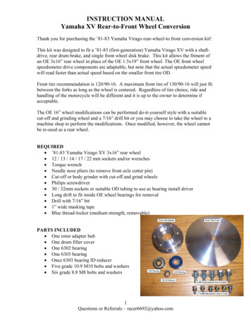
Fractured toothMoving directionFig.1 Macro appearance of the failed gearMain sourceFig.2 Macro appearance of the fractured toothWear and collision traceBlack regionFig.3 Wear trace at working face of other teethFig.4 Wear and collision trace at addendum top2.2 Microscopic observationMicro observation shows that there exists obvious wear at the source region. No other damage is found at thesource region, shown in Fig.3. Machining trace can be found at the lateral face near the source, shown in Fig.4.Because of serious wear of the fracture surface, the depth of the machining trace at the source region cannot beaccurately measured. Fatigue striations can be seen at the propagation region, shown in Fig.5. The fast fractureregion is covered with dimples, shown in Fig.6.The black regions at the working face of other teeth present shelling-off feature due to serious wear, shown inFig.7. EDS analysis results show that the oxygen content of these regions is about 4.7%. At the working face nearthe top and at the top of some teeth, parallel wear trace can be seen, shown in Fig.7. During normal service, the topof the teeth of the output gear wouldn’t be in contact with the bottom of the teeth of input gear. According to the
parallel wear trace at the top of teeth, it can be assumed that axial float had happened to the gear. The parallel weartrace is shallow, short, and parallel, so it can be assumed that they formed a short time ago. Namely, they occurredafter the tooth fractured. The direction of the working face wear trace of the teeth is the same as that of the top wearof the teeth, so it can also be assumed that they are also related to the axial float.Fig.5 Low-magnification appearance of the main source regionFig.6 Machining trace near the main sourceFig.7 Fatigue striations at the early propagation region
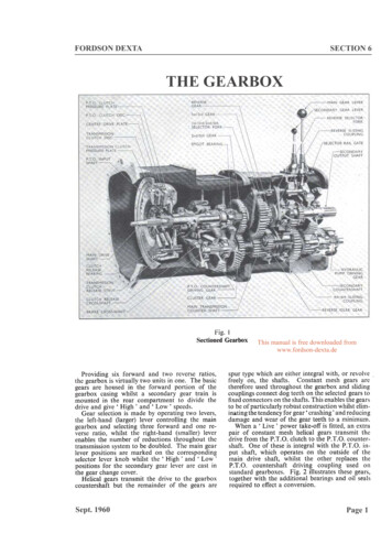
Fig.8 Dimples at the last fracture regionFig.9 Appearance of black region of working faceFig.10 Parallel wear trace at the working face near the tooth top2.3 Microstructure examinationMetallographic specimens perpendicular to the burn tooth face were cut down from the teeth near the fracturedtooth. A burn surface layer can be seen, composed of needle-shaped martensite and residual austenite(Fig.7). Thecore region is composed of lath-shaped martensite and residual austenite, shown in Fig.9. The number of theinclusions in the gear tooth is relatively small.Fig.11 High-magnification burn structure near the surfaceFig.12 Microstructure of core region of gear tooth
Fig.13 Inclusions in gear tooth2.4 Hardness and carburized depth testingSamples perpendicular to the working face were cut down from the teeth near the fractured tooth to testhardness and carburized depth. The hardness about 0.15mm away from the surface is HV669 HV679, meeting therequirement( HV660). The core hardness of the gear is HRC44.76, within the required range of HRC33 45. Thecarburized depth of the working face is 1.40mm, and that of the dedendum round angle is 1.21mm. The carburizeddepth of the non-working face is 1.30mm, and that of the dedendum round angle is 1.04mm. They all meet therequirement of 0.8 1.6mm.2.5 Round angle measurementThe dedendum round angle of three successive teeth near the fractured tooth were measured. The results areshown in Table 1. It is found that the round angle at the working face side is R0.525 0.769, far lower than therequired R1.6 0.1. The round angle at the non-working face side is R0.690 0.862, also far lower than the requiredrange.Table 1 Measurement results of dedendum round angleTesting positionWorking faceNon-working faceRound angle value R / mm1# round angle0.5252# round angle0.7273# round angle0.7691# round angle0.8262# round angle0.6903# round angle0.8622.6 Roughness measurementThe roughness of working face, non-working face and dedendum round angle was measured. According to themeasurement results, the roughness of working and non-working face, Ra, is 0.1 0.2μm; that of dedendum roundangle is 0.5 0.6μm. All meet the requirement( 1.6μm).2.7 Quantitative analysis on fracture surfaceIn order to work out the crack propagation life, quantitative analysis on the fracture surface was carried out byusing the width of fatigue striations as a key parameter. Fatigue striations can be seen at the area 1.084mm to12.64mm away from the source. The space between the striations in the extension region was measured as fatiguepropagation rate. By curve fitting, the relationship between crack propagation rate and crack length was obtained,shown in Fig.10. The results show crack propagation rate increased with the rise of crack length. Then fatiguepropagation life was obtained by listing trapezoidal method. The results show the fatigue propagation life is 33432cycles.
1.0Space between fatigue striations /μ m0.90.80.70.60.50.40.30.20.10.003691215Crack propagation length / mmFig.10 Relationship between crack propagation rate and crack length3. DiscussionAccording to the beach marks and fatigue striations at the fracture surface, it can be assumed that the gearfailed by fatigue fracture. The fatigue region almost accounts for 80% of the whole fracture surface, so it can befurther assumed that the failure mode of the gear is high-cycle fatigue. The fatigue crack initiated from the workingface at the dedendum round angle, and propagated in the depth direction. Based on quantitative analysis on fracturesurface, the propagation life between the point 1.084mm away from the surface source and the last point wherefatigue feature can be seen is 33432 cycle.Surveying gear failure cases in the literature reveals that there are many causes for gear failure, includingfaulty design, poor manufacturing and heat treatment practices, improper installation and operation, and poormaintenance. One or more of these causes may lead to surface and or subsurface deteriorations, stress concentration,impact or continuous overloading which, in turn, lead to eventual failure of gears. Fatigue fracture is found to bethe most common fracture mode, and most fatigue cracks originated at the surface or subsurface of gears, becausethe possibility for creating stress raisers, the key ingredient for fatigue crack initiation, is the greatest at the surfaceor subsurface. Pitting, sharp notches, surface deteriorations, poor machining and grinding marks are examples ofstress raisers at the surface. Internally initiated fatigue cracks due to faulty materials and poor heat treatmentpractice, such as inclusions and other inhomogeneities, are rare[4-6].From the observations, it is clear that the tooth fracture is typical bending fatigue failure. Tooth bendingfatigue is one of the most common modes of fatigue failure for gears. Since the maximum tensile stresses occur atthe root round angle at the working face side of the gear teeth, gear-tooth failure from bending fatigue generallyresults from a crack originating in the root section of the gear tooth[1,2]. The whole tooth, or a part of the tooth,breaks away. The microstructure, hardness, carburized depth and roughness are satisfactory and within thespecification. According to round angle testing results, the working face round angle of the gear teeth is far smallerthan required, which would result in stress raisers and promote the initiation of fatigue cracks. In order to improvethe fatigue life, the manufacture processes of the gear should be concisely controlled.4. Conclusion and recommendationsThe gear failed by fatigue fracture. The crack initiated from the working face of the dedendum round angle.The working face round angle of the gear teeth is smaller than required, resulting in stress raisers, which is the maincause for the fatigue fracture of the gear. It is recommended that the manufacturing processes of the dedendumround angle should be concisely controlled.References:[1] Failure analysis and prevention. ASM handbook, vol. 11. Metals Park (OH): American Society for Metals; 1986.
[2] Fernandes PJL.Tooth bending fatigue failures in gears.Engineering Failure Analysis,1996,3:219–225.[3] Asi Osman.Fatigue failure of a helical gear in a gearbox.Engineering Failure Analysis,2006,13(7):1116–1125.[4] Samroeng Netpu, Panya Srichandr. Failure of a helical gear in a power plant.Engineering Failure Analysis,2013,32:81–90.[5] Martin R, Karen S. Fatigue failure of carburized steel gear from a helicopter transmission. In: Handbook of case histories in failureanalysis. OH: ASM International; 1992. 228–230.[6] Becker WT, Shipley JR, editors. Failure analysis and prevention, ASM handbook, vol. 11. OH: ASM International; 2007. 718–720.
Failure Analysis on Rear Gearbox Output Gear of Helicopter LIU Changkui,ZHANG Bing,CHEN Xing,TAO Chunhu,LIU Delin AVIC Failure Analysis Center, Beijing Institute of Aeronautical Materials, Beijing 100095, China Abstract: A tooth of a rear gearbox output gear in a helicopter fractured after service for a period. The failure mode and causes of the gear were analyzed