Transcription
Electric Drives and Electromechanical Systems
This page intentionally left blank
Electric Drives andElectromechanical SystemsRichard CrowderAmsterdam Ɣ Boston Ɣ Heidelberg Ɣ London Ɣ New York Ɣ OxfordParis Ɣ San Diego Ɣ San Franciso Ɣ Singapore Ɣ Sydney Ɣ TokyoButterworth-Heinemann is an imprint of Elsevier
Butterworth-Heinemann is an imprint of ElsevierLinacre House, Jordan Hill, Oxford OX2 8DP, UKThe Boulevard, Langford Lane, Kidlington, Oxford OX5 1GB, UK84 Theobald's Road, London WC1X 8RR, UKRadarweg 29, PO Box 211, 1000 AE Amsterdam, The Netherlands30 Corporate Drive, Suite 400, Burlington, MA 01803, USA525 B Street, Suite 1900, San Diego, CA 92101-4495, USAFirst edition 2006Copyright 2006, Richard Crowder. Published by Elsevier 2006. All rights reservedThe right of Richard Crowder to be identified as the author of this work has beenasserted in accordance with the Copyright, Designs and Patents Act 1988No part of this publication may be reproduced, stored in a retrieval systemor transmitted in any form or by any means electronic, mechanical, photocopying,recording or otherwise without the prior written permission of the publisherPermissions may be sought directly from Elsevier's Science & Technology RightsDepartment in Oxford, UK: phone ( 44) (0) 1865 843830; fax ( 44) (0) 1865 853333;email: permissions@elsevier.com. Alternatively you can submit your request online byvisiting the Elsevier web site at http://elsevier.com/locate/permissions, and selectingObtaining permission to use Elsevier materialNoticeNo responsibility is assumed by the publisher for any injury and/or damage to personsor property as a matter of products liability, negligence or otherwise, or from any useor operation of any methods, products, instructions or ideas contained in the materialherein. Because of rapid advances in the medical sciences, in particular, independentverification of diagnoses and drug dosages should be madeBritish Library Cataloguing in Publication DataA catalogue record for this book is available from the British LibraryLibrary of Congress Cataloging-in-Publication DataA catalog record for this book is availabe from the Library of CongressISBN–13: 978-0-7506-6740-1ISBN–10: 0-7506-6740-0For information on all Butterworth-Heinemann publicationsvisit our web site at books.elsevier.comPrinted and bound in Great Britain06 07 08 09 10 10 9 8 7 6 5 4 3 2 1
ContentsPrefacexiList of principal symbols12xiiiElectromechanical systems1.1 Principles of automation . . . . . . . . .1.2 Machine tools . . . . . . . . . . . . . . .1.2.1 Conventional machining processes1.2.2 Non-conventional machining . . .1.2.3 Machining centres . . . . . . . .1.3 Robots . . . . . . . . . . . . . . . . . . .1.3.1 Industrial robots . . . . . . . . .1.3.2 Robotic hands . . . . . . . . . .1.3.3 Mobile robotics . . . . . . . . . .1.3.4 Legged robots . . . . . . . . . . .1.4 Other applications . . . . . . . . . . . . .1.4.1 Automotive applications . . . . .1.4.2 Aerospace applications . . . . . .1.5 Motion-control systems . . . . . . . . . .1.6 Summary . . . . . . . . . . . . . . . . .Analysing a drive system2.1 Rotary systems . . . . . . . . . . . . . . . . . . .2.1.1 Fundamental relationships . . . . . . . . .2.1.2 Torque considerations . . . . . . . . . . .2.1.3 Gear ratios . . . . . . . . . . . . . . . . .2.1.4 Acceleration without an external load . . .2.1.5 Acceleration with an applied external load .2.1.6 Accelerating loads with variable inertias . .2.2 Linear systems . . . . . . . . . . . . . . . . . . .2.3 Friction . . . . . . . . . . . . . . . . . . . . . . .2.4 Motion profiles . . . . . . . . . . . . . . . . . . .2.5 Assessment of a motor-drive system . . . . . . . 44652
CONTENTSvi2.62.5.1 Mechanical compatibility . . . .2.5.2 Electromagnetic compatibility .2.5.3 Wiring considerations . . . . .2.5.4 Supply considerations . . . . .2.5.5 Protection from the environment2.5.6 Drive hazards and risk . . . . .Summary . . . . . . . . . . . . . . . .525355576162703Power transmission and sizing713.1 Gearboxes . . . . . . . . . . . . . . . . . . . . . . . . . . . . . . 723.1.1 Planetary gearbox . . . . . . . . . . . . . . . . . . . . . . 723.1.2 Harmonic gearbox . . . . . . . . . . . . . . . . . . . . . 753.1.3 Cycloid gearbox . . . . . . . . . . . . . . . . . . . . . . 773.2 Lead and ball screws . . . . . . . . . . . . . . . . . . . . . . . . 783.3 Belt drives . . . . . . . . . . . . . . . . . . . . . . . . . . . . . . 813.4 Bearings . . . . . . . . . . . . . . . . . . . . . . . . . . . . . . . 853.4.1 Conventional bearings . . . . . . . . . . . . . . . . . . . 853.4.2 Air bearings . . . . . . . . . . . . . . . . . . . . . . . . . 883.4.3 Magnetic bearings . . . . . . . . . . . . . . . . . . . . . 893.5 Couplings . . . . . . . . . . . . . . . . . . . . . . . . . . . . . . 903.6 Shafts . . . . . . . . . . . . . . . . . . . . . . . . . . . . . . . . 923.6.1 Static behaviour of shafts . . . . . . . . . . . . . . . . . . 923.6.2 Transient behaviour of shafts . . . . . . . . . . . . . . . . 933.7 Linear drives . . . . . . . . . . . . . . . . . . . . . . . . . . . . 953.8 Review of motor-drive sizing . . . . . . . . . . . . . . . . . . . . 963.8.1 Continuous duty . . . . . . . . . . . . . . . . . . . . . . 983.8.2 Intermittent duty . . . . . . . . . . . . . . . . . . . . . . 993.8.3 Inability to meet both the speed and the torque requirements 1023.8.4 Linear motor sizing . . . . . . . . . . . . . . . . . . . . . 1033.9 Summary . . . . . . . . . . . . . . . . . . . . . . . . . . . . . . 1054Velocity and position transducers4.1 The performance of measurement systems . . . . . . . . . . . .4.1.1 Random errors . . . . . . . . . . . . . . . . . . . . . .4.1.2 Systematic errors . . . . . . . . . . . . . . . . . . . . .4.1.3 Digital-system errors . . . . . . . . . . . . . . . . . . .4.1.4 Analogue-digital and digital-analogue conversion errors4.1.5 Dynamic performance . . . . . . . . . . . . . . . . . .4.2 Rotating velocity transducers . . . . . . . . . . . . . . . . . . .4.2.1 Brushed d.c. tachogenerators . . . . . . . . . . . . . . .4.2.2 Brushless d.c. tachogenerators . . . . . . . . . . . . . .4.2.3 Incremental systems . . . . . . . . . . . . . . . . . . .4.2.4 Electromechanical pulse encoders . . . . . . . . . . . .4.3 Position transducers . . . . . . . . . . . . . . . . . . . . . . . .107107108111112113115115116117117118118
CONTENTS4.44.5567vii4.3.1 Brushed potentiometers . . . . . . . . . . . . .4.3.2 Linear variable differential transformers – LVDT4.3.3 Resolvers . . . . . . . . . . . . . . . . . . . . .4.3.4 Rotary and linear Inductosyn . . . . . . . . . . .4.3.5 Optical position sensors . . . . . . . . . . . . .Application of position and velocity transducers . . . . .4.4.1 Mechanical installation . . . . . . . . . . . . . .4.4.2 Electrical interconnection . . . . . . . . . . . .4.4.3 Determination of datum position . . . . . . . . .Summary . . . . . . . . . . . . . . . . . . . . . . . . .Brushed direct-current motors5.1 Review of motor theory . . . . . . . . . . . . .5.2 Direct-current motors . . . . . . . . . . . . . .5.2.1 Ironless-rotor motors . . . . . . . . . .5.2.2 Iron-rotor motors . . . . . . . . . . . .5.2.3 Torque motors . . . . . . . . . . . . .5.2.4 Printed-circuit motors . . . . . . . . .5.3 Drives for d.c. brushed motors . . . . . . . . .5.3.1 Four-quadrant thyristor converters . . .5.3.2 Linear amplifiers . . . . . . . . . . . .5.3.3 Pulse width modulated servo drives . .5.3.4 Analysis of the bipolar PWM amplifier5.3.5 PWM amplifiers . . . . . . . . . . . .5.4 Regeneration . . . . . . . . . . . . . . . . . .5.5 Summary . . . . . . . . . . . . . . . . . . . 143144145145148151155162168Brushless motors and controllers6.1 The d.c. brushless motor . . . . . . . . . . . . . . .6.1.1 Torque-speed characteristics . . . . . . . . .6.1.2 Brushless d.c. motor controllers . . . . . . .6.2 Sinewave-wound brushless motors . . . . . . . . . .6.2.1 Torque characteristics . . . . . . . . . . . .6.2.2 Voltage characteristics . . . . . . . . . . . .6.2.3 Torque-speed characteristics . . . . . . . . .6.2.4 Control of sinewave-wound brushless motors6.3 Linear motors . . . . . . . . . . . . . . . . . . . . .6.4 Summary . . . . . . . . . . . . . . . . . . . . . . .169172176178182183185185187188189Induction motors7.1 Induction motor characteristics .7.2 Scalar control . . . . . . . . . .7.3 Vector control . . . . . . . . . .7.3.1 Vector control principles.191192198202203.
CONTENTSviii.207208211211213Stepper motors8.1 Principles of stepper-motor operation . . . . .8.1.1 Multistack variable-reluctance motors .8.1.2 Single-stack variable-reluctance motors8.1.3 Hybrid stepper motors . . . . . . . . .8.1.4 Linear stepper motor . . . . . . . . . .8.1.5 Comparison of motor types . . . . . . .8.2 Static-position accuracy . . . . . . . . . . . . .8.3 Torque-speed characteristics . . . . . . . . . .8.4 Control of stepper motors . . . . . . . . . . . .8.4.1 Open-loop control . . . . . . . . . . .8.4.2 Translators and drive circuits . . . . . .8.5 Summary . . . . . . . . . . . . . . . . . . . .215216216218218221222223225226228229233Related motors and actuators9.1 Voice coils . . . . . . . . . .9.2 Limited-angle torque motors9.3 Piezoelectric motors . . . . .9.4 Switched reluctance motors .9.5 Shape-memory alloy . . . .9.6 Summary . . . . . . . . . .7.47.5897.3.2 Implementation of vector control .7.3.3 Vector control using sensors . . .7.3.4 Sensorless vector control . . . . .Matrix converter . . . . . . . . . . . . . .Summary . . . . . . . . . . . . . . . . .23523523723924024524610 Controllers for automation10.1 Servo control . . . . . . . . . . . . . . . .10.1.1 Digital controllers . . . . . . . . .10.1.2 Advanced control systems . . . . .10.1.3 Digital signal processors . . . . . .10.2 Motion controllers . . . . . . . . . . . . .10.3 Programmable logic controllers . . . . . . .10.3.1 Combinational-logic programming .10.3.2 Sequential-logic programming . . .10.4 Networks . . . . . . . . . . . . . . . . . .10.4.1 Network architecture . . . . . . . .10.4.2 Industrial networking . . . . . . . .10.4.3 SCADA . . . . . . . . . . . . . . .10.5 Summary . . . . . . . . . . . . . . . . . .247248253257257259262265267272274276279279Units and Conversion Factors.281
CONTENTSixBibliography285Index289
This page intentionally left blank
PrefaceElectrical drives play an important role as electromechanical energy converters awide range of applications, for example machine tools in manufacturing industries, photocopies, CD player, electric windows in the car, prosthetic hands andother medical devices; some are obvious other not so, until the they fail. It is critically important that the correct drive is matched to the application with due regardto its requirements. With the recent developments in power semiconductors andmicroprocessors with signal processing capabilities, the technology of the moderndrive system has changed dramatically in recent years. However, the selection ofa drive system relies on a systems approach – without which, it is highly probable that either the mechanical, electrical or electronic elements will not be fullyconsidered.A complete drive system consists of many different components, hence thisbook has been structured to present a logical discussion, on a wide range of topicsrelating to selection of the complete motor-drive system. It does not, however, extend to a detailed consideration of control and electromagnetic theory; if the readerwishes to pursue this path many excellent books are available, some of which arehighlighted in the bibliography.The structure of the book is as follows. Chapter 1 gives a brief overview ofthe problems that need to be solved, with particular emphasis on a wide rangeof electromechanical applications, including machine tools, robotics and relatedhigh performance applications. Chapters 2 and 3 concentrate on the problem ofmotor-drive selection, and give an insight into the decisions required during thisprocedure. It is hoped that this will lift the veil on what is thought by many to bea black art, or on what more commonly falls into the gap between the responsibilities of electrical, electronic, and mechanical engineers. Chapter 3 concludes withsuitable algorithms to size a wide range of applications. Chapter 4 considers thetypes, selection and installation of velocity and position transducers, the correctselection of which will have a significant impact on the overall performance of thesystem. In order to illustrate the various points in the chapters, use has been madeof a range of numerical examples, and hopefully these will show how the theorycan be applied.While the initial chapters concentrate on the mechanical aspects of a drive application, the second part of the book concentrates on the main classes of drives,which are available, and are used, to drive the applications discussed in Chapter 1.xi
xiiPrefaceThe technologies considered include: the brushed motor (Chapter 5), brushlessmotors (Chapter 6), vector controlled induction motors (Chapter 7), and the stepper motor (Chapter 8). In addition a of motor-drives fall outside this rather arbitrary classification system, and these are considered in Chapter 9. It should berecognised that some of the larger drive systems have been omitted, due to the application domain being restricted to small or medium sized applications. Withineach of theses chapters there is a review of the relevant theory, and an examinationof the specific drive and control requirements.Finally the book concludes with Chapter 10, which briefly reviews the theoryand architecture of current controllers, including the programmable logic controller(PLC). Due to the increasing reliance on decentralised control within many application domains, a review of network technologies and their current standards arepresented.The production of a book such as this is not a solitary affair although it tendsto be at times. I must acknowledge the help and assistance given by my colleaguesin industry and academia; finally I would particularly like to acknowledge my wifeLucy and my daughter Emma for their continued support throughout the writingperiod.SouthamptonMay 2005
List of principal symbolsThe following are the principal symbols used in this book. In general they arealso defined within the text. Lower-case symbols normally refer to instantaneousvalues, and upper-case symbols to constants. In practice, a symbol may refer tomore than one quantity; however, within a particular context the meaning shouldbe clear.BBgdepessEa , Eb , EcEgEkEmErfefpfsFFfFLIIef fILImItotIaIfImIrIr IRDamping constantAir-gap fluxDuty cyclePer-phase r.m.s. e.m.f.Steady-state errorDirect-current (d.c.) brushless motor back e.m.f.Tachogenerator voltageKinetic energyd.c. brushed-motor back e.m.f.Regenerative energySupply frequencySample frequencyPWM switching frequencyForceFrictional forceExternal linear forceMoment of inertia, CurrentInertia referred to the input of a gearboxLoad inertiaMotor inertiaTotal inertia of a systemArmature currentField currentInduction-motor magnetisation currentInduction-motor rotor current referred to the statorInduction-motor rotor currentRegenerative currentxiii
xivISKKeKgKpKsKtKTKT LaLsnn NNLNpNTpPPiPoRaRLRr RsRTstdtmtztoTTcmTeTfTiTLTMToTpeakTsTwT0vas , vbs , vcsList of principal symbolsInduction-motor stator currentStiffnessVoltage constant for a d.c. brushed motorTachogenerator voltage constantProportional gainEffective stiffness of a jointd.c. brushed-motor torque constantInduction-motor torque constantd.c. brushless-motor torque constantArmature inductanceInduction motor stator inductanceGear ratioOptimum gear ratioRotary speed, teeth on a gearLead-screw input speedTurns per poleNumber of teeth on belt-drive pulleyNumber of pole pairsPowerInput powerOutput powerArmature resistanceLoad resistanceReferred motor resistanceStator resistanceNumber of teeth on a stepper-motor stackSlipDwell timeTime to complete a moveTime to reach standstill under regenerationTime to reach zero terminal voltage under regenerationTorqueContinuous torque requirementElectrical torque outputFriction torqueInput torqueLoad torqueMotor torqueOutput torquePeak torqueTorque stiffnessWindage torqueStall torqueVoltages in a stationary three-axis frame
List of principal symbolsvd , vqvds , vqsV a , V b , VcVcVcpkVLVmVrVsαβ es in a rotating two-axis frameVoltages in a stationary two-axis frameBrushless-motor terminal voltagesPWM control voltage, Cutting speedPWM peak control voltageLinear speedd.c. motor terminal voltageInduction-motor induced rotor voltageSupply voltageAccelerationTorque anglePeak current deviation in a pulse width modulated driveEfficiencyDampingRotary positionStatic-position errorCoefficient of frictionLoad factor of a PWM amplifierFlux linkageRotational speedSynchronous speedInput speedInitial speed prior to application of regenerationMechanical speedNatural frequencyOutput speedRotor electrical speedSlip frequencyNo-load speedxv
This page intentionally left blank
Chapter 1Electromechanical systemsIn the design of any complex system, all the relevant design details must be considered to ensure the development of a successful product. In the development ofmotion systems, problems in the design process are most likely to occur in the actuator or motor-drive system. When designing any actuation system, mechanicaldesigners work with electrical and electronic systems engineers, and if care is nottaken, confusion will result. The objective of this book is to discuss some of theelectric motor-drive systems in common use, and to identify the issues that arise inthe selection of the correct components and systems for specific applications.A key step in the selection of any element of a drive system is a clear understanding of the process being undertaken. Section 1.1 provides an overview tothe principles of industrial automation, and sections 1.2 and 1.3 consider machinetools and industrial robotics, respectively. Section 1.4 considers a number of otherapplications domains.1.1Principles of automationWithin manufacturing, automation is defined as the technology which is concernedwith the application of mechanical, electrical, and computer systems in the operation and control of manufacturing processes. In general, an automated productionprocess can be classified into one of three groups: fixed, programmable, or flexible. Fixed automation is typically employed for products with a very high production rate; the high initial cost of fixed-automation plant can therefore bespread over a very large number of units. Fixed-automation systems are usedto manufacture products as diverse as cigarettes and steel nails. The significant feature of fixed automation is that the sequence of the manufacturingoperations is fixed by the design of the production machinery, and thereforethe sequence cannot easily be modified at a later stage of a product’s lifecycle.1
21.1. PRINCIPLES OF AUTOMATION Programmable automation can be considered to exist where the productionequipment is designed to allow a range of similar products to be produced.The production sequence is controlled by a stored program, but to achieve aproduct change-over, considerable reprogramming and tooling changes willbe required. In any case, the process machine is a stand-alone item, operating independently of any other machine in the factory; this principle ofautomation can be found in most manufacturing processes and it leads to theconcept of islands of automation. The concept of programmable automationhas its roots in the Jacquard looms of the nineteenth century, where weavingpatterns were stored on a punched-card system. Flexible automation can be considered to be an enhancement of programmable automation in which a computer-based manufacturing systemhas the capability to change the manufacturing program and the physicalconfiguration of the machine tool or cell with a minimal loss in productiontime. In many systems the machining programs are prepared at a locationremote from the machine, and they are then transmitted as required over acomputer-based local-area communication network.The basic design of machine tools and other systems used in manufacturingprocesses changed little from the eighteenth century to the late 1940s. There was agradual improvement during this period as the metal cutting changed from an art toa science; in particular, there was an increased understanding of the materials usedin cutting tools. However, the most significant change to machine-tool technologywas the introduction of numerical-control (NC) and computer-numerical-control(CNC) systems.To an operator, the differences between these two technologies are small: bothoperate from a stored program, which was originally on punched tape, but morerecently computer media such as magnetic tapes and discs are used. The storedprogram in a NC machine is directly read and used to control the machine; thelogic within the controller is dedicated to that particular task. A CNC machine toolincorporates a dedicated computer to execute the program. The use of the computergives a considerable number of other features, including data collection and communication with other machine tools or computers over a computer network. Inaddition to the possibility of changing the operating program of a CNC system, theexecutive software of the computer can be changed, which allows the performanceof the system to be modified at minimum cost. The application of NC and CNCtechnology permitted a complete revolution of the machine tool industry and themanufacturing industries it supported. The introduction of electronic systems intoconventional machine tools was initially undertaken in the late 1940s by the UnitedStates Air Force to increase the quality and productivity of machined aircraft parts.The rapid advances of electronics and computing systems during the 1960s and1970s permitted the complete automation of machine tools and the parallel development of industrial robots. This was followed during the 1980s by the integration
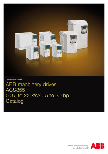
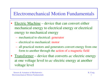
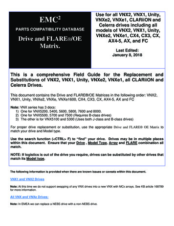
CHAPTER 1. ELECTROMECHANICAL aceSystem ComputerProcessControl1Process2.nIndividual axiscontrollersFigure 1.1. The outline of the control structure for CNC machine tool, robot orsimilar multi-axis system. The number of individual motion axes, and the interfaceto the process are determined by the system’s functionality.of robots, machine tools, and material handling systems into computer-controlledfactory environments. The logical conclusion of this trend is that individual product quality is no longer controlled by direct intervention of an operator. Since themachining parameters are stored either within the machine or at a remote locationfor direct downloading via a network (see Section 10.4) a capability exists for thecomplete repeatability of a product, both by mass production and in limited batches(which can be as small as single components). This flexibility has permitted theintroduction of management techniques, such as just-in-time production, whichwould not have been possible otherwise.A typical CNC machine tool, robot or multi-axis system, whatever its function,consists of a number of common elements (see Figure 1.1). The axis position, orthe speed controllers, and the machining-process controller are configured to forma hierarchical control structure centred on the main system computer. The overallcontrol of the system is vested in the system computer, which, apart from sequencing the operation of the overall system, handles the communication between theoperator and the factory’s local-area network. It should be noted that industrialrobots, which are considered to be an important element of an automated factory,can be considered to be just another form of machine tool. In a machine tool or
1.2. MACHINE TOOLS4industrial robot or related manufacturing systems, controlled motion (position andspeed) of the axes is necessary; this requires the provision of actuators, either linearor rotary, associated power controllers to produce motion, and appropriate sensorsto measure the variables.1.2 Machine toolsDespite advances in technology, the basic stages in manufacturing have notchanged over the centuries: material has to be moved, machined, and processed.When considering current advanced manufacturing facilities it should be remembered that they are but the latest step in a continuing process that started during theIndustrial Revolution in the second half of the eighteenth century. The machinetool industry developed during the Industrial Revolution in response to the demands of the manufacturers of steam engines for industrial, marine, and railwayapplications. During this period, the basic principles of accurate manufacturingand quality were developed by, amongst others, James Nasmyth and Joseph Whitworth. These engineers developed machine tools to make good the deficienciesof the rural workers and others drawn into the manufacturing towns of VictorianEngland, and to solve production problems which could not be solved by the existing techniques. Increased accuracy led to advantages from the interchangeabilityof parts in complex assemblies. This led, in turn, to mass production, which wasfirst realised in North America with products (such as sewing machines and typewriters) whose commercial viability could not be realised except by high-volumemanufacturing (Rolt, 1986). The demands of the market place for cost reductionsand the requirement for increased product quality has led to dramatic changes inall aspects of manufacturing industry, on an international scale, since 1970. Thesechanges, together with the introduction of new management techniques in manufacturing, have necessitated a considerable improvement in performance and costsat all stages of the manufacturing process. The response has been a considerableinvestment in automated systems by manufacturing and process industries.Machining is the manufacturing process in which the geometry of a componentis modified by the removal of material. Machining is considered to be the mostversatile of production processes since it can produce a wide variety of shapes andsurface finishes. To fully understand the requirements in controlling a machinetool, the machining process must be considered in some detail. Machining can beclassified as either conventional machining, where material is removed by directphysical contact between the tool and the workpiece, or non-conventional machining, where there is no physical contact between the tool and the workpiece.1.2.1Conventional machining processesIn a conventional machining operation, material is removed by the relative motionbetween the tool and the workpiece in one of five basic processes: turning, milling,
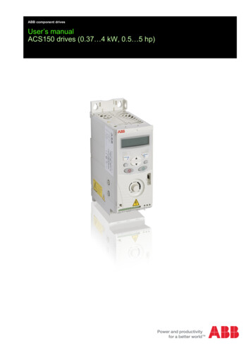
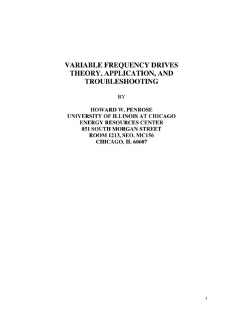
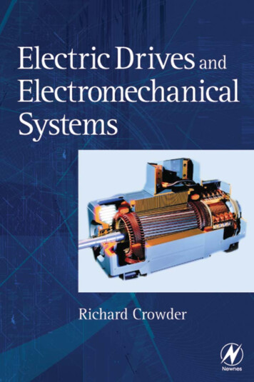
CHAPTER 1. ELECTROMECHANICAL SYSTEMS5NDdfFtFigure 1.2. The turning process, where a workpiece of initial diameter D is beingreduced to d; Ft is the tangential cutting force, N is the spindle speed, and f thefeed rate. In the diagram the depth of the cut is exaggerated.drilling, shaping, or grinding. In all machining operations, a number of processparameters must be controlled, particularly those determining the rate of materialremoval; and the more accurately these parameters are controlled the higher is thequality of the finished product (Waters, 1996). In sizing the drives of the axes inany machine tool, the torques and speed drives that are required in the machining process must be considered in detail. Figure 1.2 illustrates a turning operationwhere the tool is moved relative to the workplace. The power required by the turning operation is of most concern during the roughing cut (that is, when the cuttingdepth is at its maximum), when it is essential to ensure that the drive system willproduce sufficient power for the operation. The main parameters are the tangentialcutting force, Ft , and the cutting speed, Vc . The cutting speed is defined as therelative velocity between the tool and the surface of the workpiece (m min 1 ). Theallowable range depends on the material being cut and the tool: typical values aregiven in Table 1.1. In a turning operation, the cutting speed is directly related tothe spindle speed, N (rev min 1 ), byVc DπN(1.1)The tangential force experienced by the cutter can be determined from knowledgeof the process. The specific cutting force, K, is determined by the manufacturerof the cutting tool, and is a function of the materials involved, and of a number ofother parameters, for example, the cutting angles. T
relating to selection of the complete motor-drive system. It does not, however, ex-tend to a detailed consideration of control and electromagnetic theory; if the reader wishes to pursue this path many excellent books are available, some of which are highlighted in t