Transcription
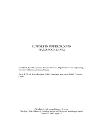
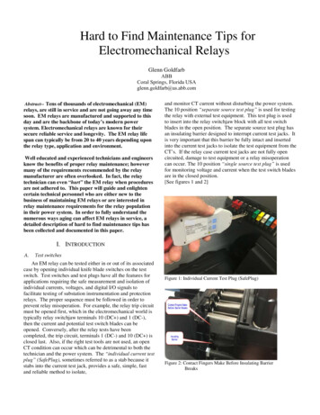
Hard to Find Maintenance Tips forElectromechanical RelaysGlenn GoldfarbABBCoral Springs, Florida USAglenn.goldfarb@us.abb.comAbstract-- Tens of thousands of electromechanical (EM)relays, are still in service and are not going away any timesoon. EM relays are manufactured and supported to thisday and are the backbone of today’s modern powersystem. Electromechanical relays are known for theirsecure reliable service and longevity. The EM relay lifespan can typically be from 20 to 40 years depending uponthe relay type, application and environment.Well educated and experienced technicians and engineersknow the benefits of proper relay maintenance; howevermany of the requirements recommended by the relaymanufacturer are often overlooked. In fact, the relaytechnician can even “hurt” the EM relay when proceduresare not adhered to. This paper will guide and enlightencertain technical personnel who are either new to thebusiness of maintaining EM relays or are interested inrelay maintenance requirements for the relay populationin their power system. In order to fully understand thenumerous ways aging can affect EM relays in service, adetailed description of hard to find maintenance tips hasbeen collected and documented in this paper.and monitor CT current without disturbing the power system.The 10 position “separate source test plug” is used for testingthe relay with external test equipment. This test plug is usedto insert into the relay switchjaw block with all test switchblades in the open position. The separate source test plug hasan insulating barrier designed to interrupt current test jacks. Itis very important that this barrier be fully intact and insertedinto the current test jacks to isolate the test equipment from theCT’s. If the relay case current test jacks are not fully opencircuited, damage to test equipment or a relay misoperationcan occur. The 10 position “single source test plug” is usedfor monitoring voltage and current when the test switch bladesare in the closed position.[See figures 1 and 2]I. INTRODUCTIONA.Test switchesAn EM relay can be tested either in or out of its associatedcase by opening individual knife blade switches on the testswitch. Test switches and test plugs have all the features forapplications requiring the safe measurement and isolation ofindividual currents, voltages, and digital I/O signals tofacilitate testing of substation instrumentation and protectionrelays. The proper sequence must be followed in order toprevent relay misoperation. For example, the relay trip circuitmust be opened first, which in the electromechanical world istypically relay switchjaw terminals 10 (DC ) and 1 (DC-),then the current and potential test switch blades can beopened. Conversely, after the relay tests have beencompleted, the trip circuit, terminals 1 (DC-) and 10 (DC ) isclosed last. Also, if the right test tools are not used, an openCT condition can occur which can be detrimental to both thetechnician and the power system. The “individual current testplug” (SafePlug), sometimes referred to as a stab because itstabs into the current test jack, provides a safe, simple, fastand reliable method to isolate,Figure 1: Individual Current Test Plug (SafePlug)Figure 2: Contact Fingers Make Before Insulating BarrierBreaks
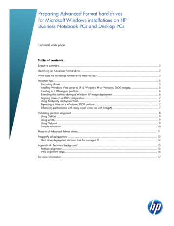
II.SAFETYPersonnel safety must always be the main focus ofconcern. The potential exposure to thousands of volts atexactly the same moment in time that a user is interactingwith the test switch can be a recipe for disaster.Significant mitigating factors come into play. Most of themitigating factors are inside the test switches, but thetechnician must be well trained for the potential danger.Since technicians extend the circuit under test with currentand voltage meters which use leads, the shock risk is nolonger contained. One relay technician who shared hisexperience removed an EM relay live not knowing therewas a missing shorting spring inside the case.Heclarified “there were allot of sparks spitting from the relaycase.” Fortunately, due to knowledge of the dangers ofan open CT condition, and some very quick reflexes;he reinserted the EM relay back into the case, thenimmediately closed the test switch blades without causingan incident to himself or the power system. By inserting therelay back into the case and closing the associated test switchblades, the relay current terminals were reconnected tothe CT secondary circuit, thereby squelching the potentiallyhigh voltage output. [See figures 3 and 4]Figure 4: Electromechanical Relay Case CT Shorting SpringWhen using the 10 position separate source test plug whilethe relay under test is in its associated case, first insert the testplug into the relay and then affix the test set leads. Whentesting is complete, the test leads must be removed, then last,the test plug afterwards. This important test procedure willprevent a current differential fault in the power system sincedigital test sets have sneak paths to earth ground. Bewaresince the separate source test plug fingers can make anelectrical connection from the test set to the relay powersystem before the current jacks are opened by the test pluginsulating barrier. It is also important not to insert test leadsinto the individual relay switchjaws unless the lead is the samethickness as the separate source test plug fingers. Otherwise aspread switchjaw can be the result which can cause anintermittent or insufficient electrical connection when themating test blade is closed. Just because someone has neverused the right tools (separate source test plug) for the last 20years, does not make it right. Like the proverbial phrase;“always use the right tool for the right job”.[See figures 5 and 6]Figure 3: EM Relay Micarta DividerFigure 5: Damaged Spread Switchjaw From Using LargeTest Lead
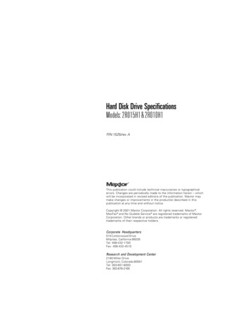
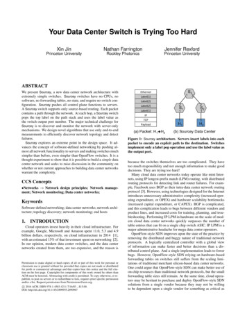
recommended that no chemicals be used to clean or lubricateEM relays. If the EM relay does not respond to or repeat therequired test parameters, friction is often the failure cause.One of the most important tools in a skilled technician’stool kit for EM relay maintenance is the contact burnishingtool. The contact burnishing tool is basically a fine metal filewhich removes oxidation and residue from the relay’s puresilver contacts. Not only should the contacts be cleaned withthe burnishing tool, but the backstops or area behind thecontact needs to be burnished or cleaned as well.B.Figure 6: Separate Source Test Plug with Warning LabelIII.VISUAL INSPECTIONGeneral visual mechanical inspection can include theinspection of hardware, wire leads, insulation, screwconnections, coils, springs, bearings, solder joints, electricalcomponents (especially capacitors) and contacts. Any form ofcorrosion, rust, burning, loose or stripped hardware,discoloration, dirt, dust, rust, particles, pitting, cracking,fraying, peeling, leaking or any damage must be identified anddocumented before the relay maintenance is performed.A.OutgassingOxidation and out gassing of a material or chemicalsolution forms a residue that causes sticking or a film on thecontacts and moving elements which can often lead to relaymisoperation. A case example of outgassing can be caused byaged neoprene rubber material. There were some AR auxiliaryrelays which were mounted in the FT -22 case which were leftin stock in a very humid environment for many years. Theneoprene gasket material on the relay case covers became softand gel like which formed an outgassing that affected thesilver contacts and actually prevented a trip operation. TheAR relay silver contact surfaces became green and needed tobe cleaned with a burnishing tool as a result. All of theaffected relay case covers were replaced and the relay contactswere cleaned with a burnishing tool which resolved the issue.[See figure 7]FrictionForeign material lodged in moving elements can causefriction in EM relays and for those that have dealt with EMrelays know that “friction” is the “enemy” of EM relays.Friction can also be described as the inability for the EM relayto repeat either its’ mechanical or test parameters andtherefore, not perform as intended. The induction discelement for example, may not return to the contact backstopafter a fault is removed due to metal particles caught under thepermanent magnet. Even the spiral spring which is used inboth the induction disc and cylinder unit elements should nothave its convolutions touch each other. In some cases thecylinder unit contacts may stick closed and not reset becauseof a bent pin bearing, damaged or cracked jewel bearing,foreign material in the moving element or chemical residue.There was a case when a couple of KD compensatordistance relay cylinder unit contacts were sticking closedafter a trip during acceptance testing. These were new relayswhich was very unusual behavior since they had all passedthe factory computer aided test. Upon further analysis it wasdiscovered that the vendor who manufactured the cylinderunit stationary contact barrel had used a protective lubricantwhich had adhered to the silver contact button. Thereforewhen the relay tripped during acceptance testing by the enduser, the contacts were sticking and intermittently remainedclosed after the test fault current was removed. In this case,the stationary barrel contacts had to be replaced. Historicallyspeaking, it is highlyFigure 7: Recommended Burnishing ToolC.Poly Vinyl Chloride (PVC)Until 1991 Poly Vinyl Chloride (PVC) wire was usedthroughout the electrical industry since its inception in the1960’s. The problem associated with PVC wire is theformation of white powder or green goo deposits that leachout of the wire insulation. The white powder is formed as aresult of a hot dry environment and the green goo is formed bya hot humid environment. The affected wire insulationdeteriorates over time which inhibits flexibility causingembrittlement and minimizes its dielectric capabilities. Theleaching deposit formations are chloride based and arehazardous but not considered to be highly toxic. The depositshave been known to cause skin and eye irritation, so handlingof the affected EM Relay with gloves is recommended. Thelesson here is the possibility of the white powder or green gooto form on relay contacts, behind the contact at the backstop orsimply fall into any moving element of the EM relay. Therehave been reports of the green goo and white powder causingthe contacts to either not make due to the material’s insulating
properties or cause the contacts to stick in the open positionand not operate even when test or fault current was applied. Ifthe EM relays in the power system are affected,recommendations are to attempt to clean the white powder andgreen deposit residue with paper towels or a lint free cottoncloth. If the outbreak is excessive, replacement is in order.[See figure 8]Figure 9: Nickel Whiskers Formation on Permanent MagnetE.Figure 8: PVC Wire White Powder and Green Goo FormationD.Metallic whiskersMetallic (tin) whiskers have been reported and can affectnot only EM relays, but solid state relays alike. Metallicwhiskers can be formed on virtually all metallic surfaceswhich can include tin, zinc, silver and even gold. Thestructures often require a flashlight and magnifying glass forvisual indication. The metallic whiskers are (conductive)crystalline structures that are capable of causing mechanicalmisoperation as well as electrical short circuits. Mechanicalmisoperation is often caused by the whisker obstructionformed between moving mechanisms such as the auxiliarytelephone relay armature and the adjacent coil pole face. TheICS (indicating contactor switch) is another critical unit toinspect whereas the tin or zinc whiskers can be formed on thearmature. Tin whiskers can form under the induction discrelay permanent magnet which can slow or stop the movingdisc from resetting after a fault condition is removed. Metallicwhisker formed short circuits are often caused by bridgingelectrical contacts or electrical component lead connections ofadjacent components. Recommendations are to attempt toclean the surface with a lint free cloth or paper towel. Maskingor double sided tape can be used between the permanentmagnet and the disk to remove metal particles. [See figure 9]CapacitorsOil-filled capacitors have been used in most types of EMrelays for many years and have an expected service life of 20plus years. Most of the capacitors in today’s EM relay inservice population can be affected since they are reaching orhave reached their end of life. Aged capacitor failure modescan include loss of capacitance, shorting internally and leakingoil at the terminals and the metal can seams. KD relaycapacitors C3C in particular runs hot and has a high voltageapplied from the in series XL coil. This cap historically hascaused issues and has often caused tomato shaped impedancecircles which should be round when plotted. Capacitorsmanufactured in the 1970’s used polychlorinated biphenyls(PCB’s) which are an excellent dielectric due to its insulatingproperties and perform well under high temperature exposureand over time. However, PCB’s have been known to belinked to certain health hazards and therefore extreme caremust be taken when handling. Users of PCB capacitors mustdispose of them per applicable EPA (environmental)requirements. After 1978, PCB capacitors were no longermanufactured and the caps were labeled “No PCB” on the can.In many instances, capacitors can be replaced; however themaintenance technician must be aware since it is likely relaycalibration adjustments have been made to compensate for thecontinual drift in capacitance. This is sometimes referred to as“chasing the cap”.The other capacitors in question are the wet slug typetantalums or electrolytic type typically identified by a silvercolored body with a band at one end and manufactured with anelastomeric seal. According to a capacitor manufacturer; athigher ambient temperatures and high ripple voltage riding onthe dc voltage, this type of sealed capacitor may tend to leakover time. A common mode failure occurs whereas the sealedcapacitor may tend to leak its electrolyte. When this occurs, agreenish gel type substance or white crystals form from one orboth ends of the capacitor. This anomaly can cause corrosionaround the soldered terminals or dark spots on the body of thecapacitor. This may eventually lead to module circuit damageor relay failure. Older LCB II current differential solid staterelays have been linked to false trips due to leaking tantalumcaps. Preventative maintenance annually by visual inspectionand capacitor replacement can prevent this common modefailure characteristic. In newer designs, the capacitors have
been permanently replaced by improved hermetically sealedcapacitors.[See figure 10]Figure 11: Peeling Paint on Aged Painted Cloth Type ElectromagnetIV.Figure 10: Oil Filled PCB Capacitors - Replaced after 1978F.Adjustable ResistorsAdjustable ceramic slide adjusted resistors are typicallywound with fine wire whereas a slide is used to set a certainvalue along an exposed area. If the slide strap is not loosenedor is tightened down too tight, damage to the fine strands canoccur. The adjustment should not be along the edge of theopen area since ceramic material can interfere with theelectrical connection. Also the resistor slide strap can bedamaged or broken if proper care is not taken whentightening. The higher the resistor value the finer the wirestrands.G.PaintBlack enamel paint is used to seal laminations and wasoften used to keep the cotton cloth coils and bobbins fromfraying. The paint also protected solid copper wire leads andre-enforced the relay’s dielectric capability. Peeling paint onaged EM relays can be a concern because the paint particlescan possibly become lodged in moving elements such as theinduction disc, cylinder unit or even between trip contacts.Today’s EM relays still use black enamel paint to seallaminations and protect copper wire coils and electromagnets.Peeling paint can be serious and can be cleaned out of therelay however if the peeling is excessive relay replacementcan be in order. [See figure 11]H.Oil can effectOil canning or oil can springs typically have a toggling popin and out effect. Oil can springs when dealing with EM relayshas a negative connotation. EM relay springs must move backand forth smoothly without any toggling or popping effect.Examples of oil can springs can be found in IndicatingContactor Switch (ICS) cover leaf springs and polar unitarmature contact fingers. In respect to polar unit contactfingers, if the contact does not reset, this can be the cause.There is no method to correct this issue, therefore replacementis the only option.MAINTENANCE TESTINGEM relay functional testing ensures relay calibration ismaintained. Relay testing should be performed per the relayinstruction book acceptance test or performance checks.Sometimes taps or settings need to be changed in order toperform a particular test so careful documentation needs to benoted for the as found state. Certain tests require specificsettings and calculations for a particular application. The EMrelay instruction book (I.L.) must be the source of referencewhen testing is performed.From a manufacturer’s standpoint, EM relay maintenanceshould be performed every 1 to 2 years which includes relaytesting. This requirement is often documented in the relayinstruction book prior to the acceptance test or performancecheck. The frequency when EM relay maintenance should beperformed is also dependent upon the relay type, environmentand how often the relay is operated. Relay training is crucialfor personnel who deal with EM relays. Factory authorizedtraining is available for EM relays which includes relayapplications, mechanical and visual inspection, acceptancetesting and maintenance.Sometimes relay contacts need to be blocked open orclosed in order to sense or verify continuity that a certain relayelement is functioning properly. This can be achieved byusing a small folded piece of paper between the relay contacts,contact backstop or moving element; i.e. relay disc and frame.White paper can also be used as a lighted background whentrying to see clearances and particles between the inductiondisc and electromagnets and permanent magnets. A foldedfive dollar bill is often used since no respectable relaytechnician will leave his money in the relay when all tests arecompleted and the relay cover is put back on.
EM relays are often referred to as “Silent Sentinels” andwill remain silent, operating only for a fault condition withinthe power system. Proper training and experience are a goodmix for preventing a relay misoperation and keeping thetechnician safe. EM relays that are properly maintained intoday’s modern power system are our assurance that electricpower will remain reliable and secure while preventing: Power System misoperations (blackouts)Damage to overall equipment the relay was designedto protectPersonnel safety (shock hazard)With due diligence, relay maintenance, proper use of testequipment, test tools and knowing what to look for; risk canbe mitigated.REFERENCES[1][2]FT Switch Descriptive Bulletin – DB 41-077 Rev D March 2011A. Elmore, Protective Relaying: Theory and Application,Marcel Decker, Inc., 1994.[3] IEEE Standard for Relays and Relays Systems Associated withElectric Power Apparatus. IEEE Std. C37-90, 200513BIOGRAPHYGlenn Goldfarb has been best known as “the Answer Man”during most of his career at ABB. Currently, SeniorMarketing Engineer at ABB’s Coral Springs, Florida, plant, hehas been the go-to person for questions aboutelectromechanical relays and FT switches. He has also beenresponsible for high-voltage microprocessor-based relays inABB Allentown, Pennsylvania, and for recloser controlproducts at ABB Lake Mary, Florida. He has a total of 38years of experience with Westinghouse and ABB relayproducts and is the primary instructor for ElectromechanicalHands-On Relay Training. In fact,
AR relay silver contact surfaces became green and needed to be cleaned with a burnishing tool as a result. All of the affected relay case covers were replaced and the relay contacts were cleaned with a burnishing tool which resolved the issue. [See figure 7] Figure 7: Recommended Burnishing