Transcription
VARIABLE FREQUENCY DRIVESTHEORY, APPLICATION, ANDTROUBLESHOOTINGBYHOWARD W. PENROSEUNIVERSITY OF ILLINOIS AT CHICAGOENERGY RESOURCES CENTER851 SOUTH MORGAN STREETROOM 1213, SEO, MC156CHICAGO, IL 606071
.1.0Introduction . 32.0Alternating Current Induction Motor Design. 32.1Introduction . 32.2The Purpose of Induction Motors. 32.3Induction Motor Construction. 42.4Operating Principles. 52.5Torque . 62.6NEMA Motor Design Classifications. 62.7Design E Motor Discussion . 72.8Electric Motor Insulation. 82.9Energy Efficient Electric Motors . 92.10 Inverter Duty Motors. 103.0Variable Frequency Drives. 113.1Variable Torque Loads. 113.2Constant Torque Loads. 123.3Basic Drive System . 123.4Basic Operation of a PWM Inverter (VFD). 134.0Application Considerations . 144.1Variable Speed Concerns. 144.2Power Quality . 154.3Inverter Duty Failures . 165.0Troubleshooting Drives. 172
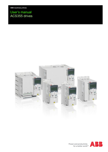
1.0IntroductionIn this presentation, we will be covering Variable Frequency Drives (VFD’s) and theirtheory, application, and troubleshooting. In order to properly cover the subject, it will bebroken into four distinct parts: Induction motor theory; VFD theory; Power quality; andTroubleshooting.2.0Alternating Current Induction Motor Design2.1IntroductionElectric motor systems consume 20% of all energy generated in the United States, 57%of all electrical energy, and 70% of electrical energy consumed by industry. Over 1.1billion motors, of all types, are presently in use in the United States at this time.Induction motors were invented by Nikola Tesla in 1888 while he was a college student.In the present day, induction motors consume between 90 to 95 percent of the motorenergy used in industry.In the first part of our presentation, we are going to discuss:qqqqqqq2.2The purpose of induction motorsInduction motor constructionOperating principlesNEMA DesignsDesign E motor discussionMotor insulationInverter duty motor constructionThe Purpose of Induction MotorsContrary to popular belief, induction motors consume very little electrical energy.Instead, they convert electrical energy to mechanical torque (energy). Interestinglyenough, the only component more efficient than the motor, in a motor system, is thetransformer. The mechanical torque that is developed by the electric motor is transferred,via coupling system, to the load.The electrical energy that is consumed by electric motors is accounted for in losses.There are two basic types of losses, Constant and Variable, both of which develop heat(Figure 1):qCore Losses: A combination of eddy-current and hysterisis losses within the statorcore. Accounts for 15 to 25 percent of the overall losses.3
qqqqFriction and Windage Losses: Mechanical losses which occur due to air movementand bearings. Accounts for 5 to 15 percent of the overall losses.Stator Losses: The I2R (resistance) losses within the stator windings. Accounts for 25to 40 percent of the overall losses.Rotor Losses: The I2R losses within the rotor windings. Accounts for 15 to 25percent of the overall losses.Stray Load Losses: All other losses not accounted for, such as leakage. Accounts for10 to 20 percent of the overall 5025%2.350%75%100%125%Induction Motor ConstructionAn induction motor consists of three basic components:qqqStator: Houses the stator core and windings. The stator core consists of many layersof laminated steel, which is used as a medium for developing magnetic fields. Thewindings consist of three sets of coils separated by 120 degrees electrical.Rotor: Also constructed of many layers of laminated steel. The rotor windingsconsist of bars of copper or aluminum alloy shorted, at either end, with shorting rings.Endshields: Support the bearings which center the rotor within the stator.4
2.4Operating PrinciplesThe basic principle of operation is for a rotating magnetic field to act upon a rotorwinding in order to develop mechanical torque.The stator windings of an induction motor are evenly distributed by 120 degreeselectrical. As the three phase current enters the windings, it creates a rotating magneticfield within the air gap (the space between the rotor and stator laminations). The speedthat the fields travel around the stator is known as synchronous speed (Ns). As themagnetic field revolves, it cuts the conductors of the rotor winding and generates acurrent within that winding. This creates a field which interacts with the air gap fieldproducing a torque. Consequently, the motor starts rotating at a speed N Ns in thedirection of the rotating field.The speed of the rotating magnetic field can be determined as:Ns (120 * f) / peq. 1Where Ns is the synchronous speed, f is the line frequency, and p is the number of polesfound as:p (# of groups of coils) / 3eq. 2The number of poles is normally expressed as an even number.The actual output speed of the rotor is related to the synchronous speed via the slip, orpercent slip:s (Ns - N) / Ns%s s * 100eq. 3eq. 45
2.5TorqueBy varying the resistance within the rotor bars of a squirrel cage rotor, you can vary theamount of torque developed. By increasing rotor resistance, torque and slip areincreased. Decreasing rotor resistance decreases torque and slip.Motor horsepower is a relation of motor output speed and torque (expressed in lb-ft):HP (RPM * Torque) / 5250eq. 5The operating torques of an electric motor are defined as (Ref. NEMA MG 1-1993, Part1, p.12):qqqq2.6Full Load Torque: The full load torque of a motor is the torque necessary to produceits rated horsepower at full-load speed. In pounds at a foot radius, it is equal to the hptimes 5250 divided by the full-load speed.Locked Rotor Torque: The locked-rotor torque of a motor is the minimum torquewhich will develop at rest for all angular positions of the rotor, with rated voltageapplied at rated frequency.Pull-Up Torque: The pull-up torque of an alternating current motor is the minimumtorque developed by the motor during the period of acceleration from rest to the speedat which breakdown torque occurs. For motors which do not have a definitebreakdown torque, the pull-up torque is the minimum torque developed up to ratedspeed.Breakdown Torque: The breakdown torque of a motor is the maximum torque whichit will develop with rated voltage applied at rated frequency, without an abrupt dropin speed.NEMA Motor Design ClassificationsNEMA defines, in NEMA MG 1-1993, four motor designs dependant upon motor torqueduring various operating stages:qqDesign A: Has a high starting current (not restricted), variable locked-rotor torque,high break down torque, and less than 5% slip.Design B: Known as "general purpose" motors, have medium starting currents (500 -6
qq800% of full load nameplate), a medium locked rotor torque, a medium breakdowntorque, and less than 5% slip.Design C: Has a medium starting current, high locked rotor torque (200 - 250% offull load), low breakdown torque (190 - 200% of full load), and less than 5% slip.Design D: Has a medium starting current, the highest locked rotor torque (275% offull load), no defined breakdown torque, and greater than 5% slip.Design A and B motors are characterized by relatively low rotor winding resistance.They are typically used in compressors, pumps, fans, grinders, machine tools, etc.Design C motors are characterized with dual sets of rotor windings. A high resistiverotor winding, on the outer, to introduce a high starting torque, and a low resistivewinding, on the inner to allow for a medium breakdown torque. They are typically usedon loaded conveyers, pulverizers, piston pumps, etc.Design D motors are characterized by high resistance rotor windings. They are typicallyused on cranes, punch presses, etc.2.7Design E Motor DiscussionThe design E motor was specified to meet and international standard promulgated by theInternational Electrotechnical Commission (IEC). IEC has a standard which is slightlyless restrictive on torque and starting current than the Design B motor. The standardallows designs to be optimized for higher efficiency. It was decided to create a newDesign E motor which meets both the IEC standard and also an efficiency criteriongreater than the standard Design B energy efficient motors.For most moderate to high utilization application normally calling for a Design A or Bmotor, the Design E motor should be a better choice. One should be aware of slightperformance differences.Although the NEMA standard allows the same slip (up to 5%) for Designs A, B, and Emotors, the range of actual slip of Design E motors is likely to be lower for Designs Aand B.There are a number of considerations which must be observed with Design E motors:qqqqqqqGood efficiency - as much as 2 points above Design B energy efficient.Less Slip - Design E motors operate closer to synchronous speed.Lower Starting Torque - May not start "stiff" loads.High Inrush - As much as 10 times nameplate full load amps.Availability - Presently low as the standard has just passed.Starter Availability - Control manufacturers do not have an approved starterdeveloped at this time.National Electric Code - Has no allowance for higher starting amps. Design E motorswill require changes to NEC allowances for wire size and feed transformers.7
qq2.8Limited Applications - Low starting torque limits applications to pumps, blowers, andloads not requiring torque to accelerate load up to speed.Heavier Power Source Required - High amperage and low accelerating torque meanlonger starting time and related voltage drops. May cause nuisance tripping of starterof collapse of SCR field with soft starters.Electric Motor InsulationWith all this discussion about motor operation, losses, torque curves, and inrush, it is onlyfitting to review the thermal properties of electrical insulation. In general, when anelectric motor operates, it develops heat as a by-product. It is necessary for the insulationthat prevents current from going to ground, or conductors to short, to withstand theseoperating temperatures, as well as mechanical stresses, for a reasonable motor life.Insulation life can be determined as the length of time at temperature. On average, thethermal life of motor insulation is halved for every increase of operating temperature by10 degrees centigrade (or doubled, with temperature reduction).Table 2: Maximum Temperatures of Common Insulation ClassesInsulation ClassTemperature, oCA105B130F155H180There are certain temperature limitations for each insulation class (Table 3) which can beused to determine thermal life of electric motors. Additionally, the number of starts amotor sees will also affect the motor insulation life. These can be found as mechanicalstresses and as a result of starting surges.When a motor starts, there is a high current surge (as previously described). In the caseof Design B motors, this averages between 500 to 800% of the nameplate current. Thereis also a tremendous amount of heat developed within the rotor as the rotor current andfrequency is, initially, very high. This heat also develops within the stator windings.In addition to the heat developed due to startup, there is one major mechanical stressduring startup. As the surge occurs in the windings, they flex inwards towards the rotor.This causes stress to the insulation at the points on the windings that flex (usually at thepoint where the windings leave the slots).Both of these mean there are a limited number of starts per hour (Figure 4). These limitsare general, the motor man
In this presentation, we will be covering Variable Frequency Drives (VFD’s) and their theory, application, and troubleshooting. In order to properly cover the subject, it will be broken into four distinct parts: Induction motor theory; VFD theory; Power quality ; and Troubleshooting. 2.0 Alternating Current Induction Motor Design 2.1 IntroductionFile Size: 266KBPage Count: 17