Transcription
Electromechanical Motion Fundamentals Electric Machine – device that can convert eithermechanical energy to electrical energy or electricalenergy to mechanical energy– mechanical to electrical: generator– electrical to mechanical: motor– all practical motors and generators convert energy from oneform to another through the action of a magnetic field Transformer – device that converts ac electric energyat one voltage level to ac electric energy at anothervoltage levelSensors & Actuators in MechatronicsElectromechanical Motion FundamentalsK. Craig1
– It operates on the same principles as generators and motors,i.e., it depends on the action of a magnetic field toaccomplish the change in voltage level Motors, Generators, and Transformers are ubiquitousin modern daily life. Why?– Electric power is: Clean Efficient Easy to transmit over long distances Easy to control Environmental benefitsSensors & Actuators in MechatronicsElectromechanical Motion FundamentalsK. Craig2
Purpose of this Study– provide basic knowledge of electromechanical motiondevices for mechatronic engineers– focus on electromechanical rotational devices commonlyused in low-power mechatronic systems permanent magnet dc motor brushless dc motor stepper motor Topics Covered:– Magnetic and Magnetically-Coupled Circuits– Principles of Electromechanical Energy ConversionSensors & Actuators in MechatronicsElectromechanical Motion FundamentalsK. Craig3
References Electromechanical Motion Devices, P. Krause and O.Wasynczuk, McGraw Hill, 1989. Electromechanical Dynamics, H. Woodson and J. Melcher,Wiley, 1968. Electric Machinery Fundamentals, 3rd Edition, S. Chapman,McGraw Hill, 1999. Driving Force, The Natural Magic of Magnets, J. Livingston,Harvard University Press, 1996. Applied Electromagnetics, M. Plonus, McGraw Hill, 1978. Electromechanics and Electric Machines, S. Nasar and L.Unnewehr, Wiley, 1979.Sensors & Actuators in MechatronicsElectromechanical Motion FundamentalsK. Craig4
Magnetic & Magnetically-Coupled Circuits IntroductionMagnetic FieldMagnetic CircuitsProperties of Magnetic MaterialsFarady’s Law and Lenz’s LawProduction of an Induced Force on a WireInduced Voltage on a Conductor Moving in aMagnetic FieldSensors & Actuators in MechatronicsElectromechanical Motion FundamentalsK. Craig5
Linear DC Machine – A Simple Example Stationary Magnetically-Coupled Circuits Magnetic Systems with Mechanical Motion– Elementary Electromagnet– Elementary Reluctance Machine– Windings in Relative MotionSensors & Actuators in MechatronicsElectromechanical Motion FundamentalsK. Craig6
Introduction Review concepts and terms for use in the study ofelectromechanical motion devices. In all electromechanical devices, mechanical motionmust occur, either translational or rotational, and thismotion is reflected into the electrical system either asa change of flux linkages (electromagnetic system) oras a change of charge (electrostatic system). Focus is primarily on electromagnetic systems.Sensors & Actuators in MechatronicsElectromechanical Motion FundamentalsK. Craig7
If the magnetic system is linear, then the change influx linkages results owing to a change in theinductance, i.e., inductances of electric circuitsassociated with electromechanical motion devices arefunctions of the mechanical motion. Learn to express self- and mutual-inductances forsimple translational and rotational electromechanicaldevices, and to handle these changing inductances inthe voltage equations describing the electrical circuitsassociated with the electromechanical system.Sensors & Actuators in MechatronicsElectromechanical Motion FundamentalsK. Craig8
Magnetic Field 10 facts about The Force– Known for Hundreds of Years If free to rotate, permanent magnets point approximatelynorth-south. Like poles repel, unlike poles attract. Permanent magnets attract some things (like iron and steel),but not others (like wood and glass). Magnetic forces attractonly magnetic materials. Magnetic forces act at a distance, and they can act throughnonmagnetic barriers. Things attracted to a permanent magnet become temporarymagnets themselves.Sensors & Actuators in MechatronicsElectromechanical Motion FundamentalsK. Craig9
– Known only since the 19th Century A coil of wire with an electric current running through itbecomes a magnet. Putting iron inside a current-carrying coil greatly increasesthe strength of the electromagnet. A changing magnetic field induces an electric current in aconductor (like copper). A charged particle experiences no magnetic force whenmoving parallel to a magnetic field, but when it is movingperpendicular to the field it experiences a force perpendicularto both the field and the direction of motion. A current-carrying wire in a perpendicular magnetic fieldexperiences a force perpendicular to both the wire and thefield.Sensors & Actuators in MechatronicsElectromechanical Motion FundamentalsK. Craig10
Magnetic Fields are the fundamental mechanism bywhich energy is converted from one form to anotherin motors, generators, and transformers. Four Basic Principles describe how magnetic fieldsare used in these devices:– A current-carrying wire produces a magnetic field in thearea around it.– A time-changing magnetic field induces a voltage in a coilof wire if it passes through that coil (basis of transformeraction).– A current-carrying wire in the presence of a magnetic fieldhas a force induced on it (basis of motor action).– A moving wire in the presence of a magnetic field has avoltage induced in it (basis of generator action).Sensors & Actuators in MechatronicsElectromechanical Motion FundamentalsK. Craig11
In the study of electricity, one learns that stationarycharges produce an electric field. If the charges move with uniform velocity, asecondary effect takes place: magnetism If we accelerate charges, there is an additional effect;the accelerated charges now produce a radiatingelectromagnetic field, i.e., a field that can transportenergy. Magnetism and electromagnetic fields are specialcases of electricity!Sensors & Actuators in MechatronicsElectromechanical Motion FundamentalsK. Craig12
Since motion is relative, a given physical experimentwhich is purely electrostatic in one coordinate systemcan appear as electromagnetic in another coordinatesystem that is moving with respect to the first.Magnetic fields seem to appear and vanish merely bya change in the motion of the observer! A magnetic field is thus associated with movingcharges. The sources of magnetic field are currents.vq 0 E 0, B 0vq 0 E 0, B 0dv qdtvq velocity of charge q 0 E 0, B 0, Radiation FieldsSensors & Actuators in MechatronicsElectromechanical Motion FundamentalsK. Craig13
Units of the Magnetic Field (SI and CGS)– Magnetic Flux Density B Also called magnetic field and magnetic induction1 tesla (T) 1 weber/meter2 (1 Wb/m2)1 T 104 G (gauss)Earth magnetic field is about 0.5 GSmall permanent magnet is about 100 GLarge electromagnet is about 20,000 G– Magnetic Field Intensity (or Strength) H 1 ampere-turn/meter 4π x 10-3 oersted (Oe)– Magnetic Flux Φ BA 1 weber (Wb) 108 maxwell (Mx)Sensors & Actuators in MechatronicsElectromechanical Motion FundamentalsK. Craig14
Magnetic Circuitsur uur Ampere’s LawÑ HgdL in– The line integral of the magnetic field intensity (ormagnetic field strength) about a closed path is equal to thenet current enclosed within this closed path of integration.Consider the elementarymagnetic circuit shown.Sensors & Actuators in MechatronicsElectromechanical Motion FundamentalsK. Craig15
Rectangular ferromagnetic core with N turns of wirewrapped about one leg of the core. The net current passing within the path of integrationis Ni. Assumptions– All the magnetic field produced by the current remainsinside the core. Therefore the path of integration is themean path length of the core.– The magnetic field intensity exists only in the direction ofthe given path of integration or, in other words,perpendicular to a cross section of the magnetic material(valid except in the vicinity of the corners).Sensors & Actuators in MechatronicsElectromechanical Motion FundamentalsK. Craig16
Carrying out the integration:Hl c Ni– The right-hand side is referred to as ampere-turns (At) ormagnetomotive force (mmf), analogous to electromotiveforce (emf) in electric circuits. The magnetic field intensity is a measure of the“effort” that a current is putting into theestablishment of a magnetic field. The strength of the magnetic field flux produced inthe core also depends on the material of the core. Forlinear, isotropic magnetic materials the magnetic fluxdensity is related to the magnetic field intensity as:rrB µHSensors & Actuators in MechatronicsElectromechanical Motion FundamentalsK. Craig17
rH magnetic field intensity (At/m; 1 At/m 0.0126 Oe)µ magnetic permeability of the material (Wb/A m or H/m)rB magnetic flux density (Wb/m 2 or T; 1 Wb/m 2 10 4 G) µ , the permeability of the medium, represents therelative ease of establishing a magnetic field in agiven material. The permeability of any other material compared tothe permeability of free space or air (µ0 ) is calledrelative permeability.µ 7µr µ0where µ 0 4π 10H/m Relative permeability is a convenient way to comparethe magnetizability of materials.Sensors & Actuators in MechatronicsElectromechanical Motion FundamentalsK. Craig18
The surface integral of the flux density is equal to ther uurtotal flux Φ (Wb) in a given area:Φ BgdSA If the flux density vector is assumed perpendicular toa plane of area, and if the flux density is constantthroughout the area, then: Φ BAµNiA In the elementary magnetic circuit: Φ BA lc Electrical / Magnetic Circuit AnalogyV iRℑ ΦℜV ℑi ΦR ℜSensors & Actuators in MechatronicsElectromechanical Motion Fundamentalsℑ Ni magnetomotive force (At)lcℜ reluctance (At/Wb)µAlR 1σA permeanceℜK. Craig19
The magnetic circuit model of magnetic behavior isoften used in the design of electric machines andtransformers to simplify the complex design process. (a) Electric Circuit and (b) Magnetic CircuitSensors & Actuators in MechatronicsElectromechanical Motion FundamentalsK. Craig20
The magnetomotive force, like voltage, has a polarityassociated with it.Modified right-hand rulefor determining the directionof the positive mmf. Reluctances in a magnetic circuit obey the same rulesfor parallel and series combinations as resistances inan electric circuit.Sensors & Actuators in MechatronicsElectromechanical Motion FundamentalsK. Craig21
Calculations of the flux in a core using magneticcircuit concepts are always approximations – accurateto within 5% at best! Why?– It is not true that all the flux is confined within themagnetic core. Flux outside the core is called leakage flux.– Calculation of reluctance assumes a certain mean pathlength and cross-sectional area for the core. Theseassumptions are not very good, especially at corners.– In ferromagnetic materials, the permeability varies with theamount of flux already in the material. This is a nonlineareffect. Reluctances depend on the permeability of thematerial.– “Fringing Effect” of the magnetic field at an air gap causesan increased effective cross-sectional area of the air gap.Sensors & Actuators in MechatronicsElectromechanical Motion FundamentalsK. Craig22
Fringing Effectof the magnetic fieldat an air gap “Corrected” mean path lengths and cross-sectionalareas can be used to offset these inherent sources oferror. Magnetic circuit concept is still the easiest design toolavailable for calculation of fluxes.Sensors & Actuators in MechatronicsElectromechanical Motion FundamentalsK. Craig23
Consider the magnetic system shown. Assume that the magnetic system (circuit) consistsonly of the magnetic member and the air gap. Apply Ampere’s Law to the elementary magneticbasystem: H dL H dL NiiaSensors & Actuators in MechatronicsElectromechanical Motion FundamentalsgbK. Craig24
– Assume that the field intensity exists only in the directionof the given path of integration or, in other words,perpendicular to a cross section of the magnetic materialtaken in the same sense as the air gap is cut through thematerial (valid except in the vicinity of the corners wherethe field intensity changes gradually rather than abruptly)– Path of integration is taken as the mean length about themagnetic member (“mean length approximation”) Carrying out the integration: Hi l i Hg l g Ni Assume that the flux density is uniformly distributedover the cross-sectional area and also perpendicularto the cross-sectional area:Φi Bi AiΦ g Bg A gSensors & Actuators in MechatronicsElectromechanical Motion FundamentalsK. Craig25
Streamlines of flux density are closed, hence the fluxin the air gap is equal to the flux in the core:ur gB 0 Maxwell's 4 th EquationΦi Φ g Φ Assume Ag A i , even though we know A g kAiwhere k 1 due to the fringing effect. Results:lgliΦ Φ Niµi A iµgAgµi µ riµ 0 ( 500 4000 ) µ 0µ g µ rg µ0 (1)µ o(ℜ ℜ ) Φ NiigSensors & Actuators in MechatronicsElectromechanical Motion FundamentalsK. Craig26
Example Problem In the magnetic system shown, the total number ofturns is 100, the relative permeability of the iron is1000, and the current is 10A. Calculate the total fluxin the center leg.Sensors & Actuators in MechatronicsElectromechanical Motion FundamentalsK. Craig27
Properties of Magnetic Materials The permeability of free space µ0 is constant. The permeability of ferromagnetic materials (e.g.,iron, nickel, cobalt) is very high (500 to 4000 timesthat of free space) but it is not constant. It dependson the mmf applied to the material. Experiment:– Apply a direct current to the elementary magnetic circuitpreviously discussed, starting with 0 A and slowly workingup to the maximum permissible current. Assume that B andH are initially zero.– Plot flux produced in the core vs. mmfSensors & Actuators in MechatronicsElectromechanical Motion FundamentalsK. Craig28
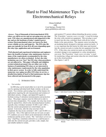
saturation regionkneeunsaturated regionlinear behaviorB µr µ0HNiH lcΦ BASaturation Curve or Magnetization Curve The relationship between B and H has the same shapeas the relationship between flux and mmf. The slope of the B vs. H curve at any value of H is,by definition, the permeability of the core at that H.Sensors & Actuators in MechatronicsElectromechanical Motion FundamentalsK. Craig29
Magnetization Curve for a Typical Piece of SteelSensors & Actuators in MechatronicsElectromechanical Motion FundamentalsK. Craig30
Relative Permeability vs. H Curve for a Typical Piece of SteelSensors & Actuators in MechatronicsElectromechanical Motion FundamentalsK. Craig31
Most real machines operate near the knee of themagnetization curve; the flux in their cores is notlinearly related to the mmf producing it. Why does the magnetization curve have this shape?– Microscopically, ferromagnetic materials have been foundto be divided into magnetic domains wherein all magneticmoments (dipoles) are aligned. Each domain acts as asmall permanent magnet. The direction of this alignmentwill differ from one domain to another; domains areoriented randomly within the material.– When a ferromagnetic material is subjected to an externalfield, it causes domains that happen to point in the directionof the field to grow at the expense of domains pointed inother directions. It is a positive feedback effect!Sensors & Actuators in MechatronicsElectromechanical Motion FundamentalsK. Craig32
– This is known as domain wall motion. As the strength ofthe magnetic field increases, the aligned domains continueto grow in a nearly linear fashion. Whole domains that arealigned in the wrong direction eventually reorientthemselves as a unit to line up with the field. A nearlylinear B-H curve results.– Soon the ability of the aligned domains to take from theunaligned domains starts to slow. This gives rise to theknee of the B-H curve and saturation is beginning.– Finally, when nearly all the atoms and domains in the ironare lined up with the external field, any further increase inthe mmf can cause only the same flux increase that itwould in free space. Once everything is aligned, there canbe no more feedback effect to strengthen the field. Thematerial is saturated with flux. Slope of B-H curve is µ0 .Sensors & Actuators in MechatronicsElectromechanical Motion FundamentalsK. Craig33
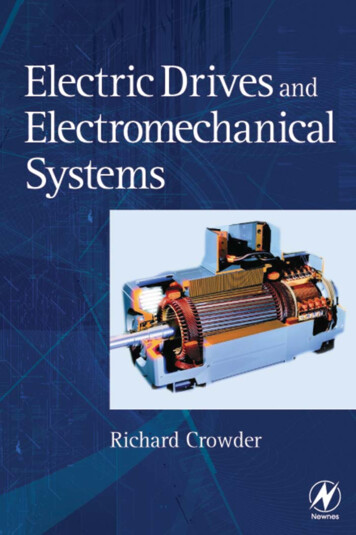
New ExperimentInstead of applying a direct currentto the windings on the core, applyan alternating current and observewhat happens. Assume that B andH are initially both zero.After several cycles, a steady-statecondition is reached.Hysteresis LoopPath b-c-d-e-b(double-valued function)Sensors & Actuators in MechatronicsElectromechanical Motion FundamentalsK. Craig34
Observations– The amount of flux present in the core depends not only onthe amount of current applied to the windings of the core,but also on the previous history of the flux in the core.– The dependence on the preceding flux history and theresulting failure to retrace flux paths is called hysteresis.– Path bcdeb traced out on the magnetization curve as theapplied current changes is called a hysteresis loop.– If a large mmf is first applied to the core and then removed,the flux path in the core will be abc. When the mmf isremoved, the flux in the core does not go to zero. Instead, amagnetic field is left in the core. This magnetic field iscalled the residual flux. It is in precisely this manner thatpermanent magnets are produced.Sensors & Actuators in MechatronicsElectromechanical Motion FundamentalsK. Craig35
– To force the flux to zero, an amount of mmf known as thecoercive magnetomotive force must be applied to the corein the opposite direction. Why does hysteresis occur?– In simple terms, the growth of aligned domains for anincremental change in H in one direction is not equal to thegrowth of oppositely aligned domains if this change in Hwere suddenly reversed.Sensors & Actuators in MechatronicsElectromechanical Motion FundamentalsK. Craig36
The diagram shows theeffect of the size of mmfexcursions on the magnitudeof the hysteresis loop.Family of Steady-State Hysteresis LoopsSensors & Actuators in MechatronicsElectromechanical Motion FundamentalsK. Craig37
Hysteresis Loss– The fact that turning domains in a ferromagnetic materialrequires energy leads to a common type of energy loss inall machines and transformers.– The hysteresis loss in an iron core is the energy required toaccomplish the reorientation of domains during each cycleof the alternating current applied to the core. The areaenclosed in the hysteresis loop formed by applying analternating current to the core is directly proportional to theenergy lost in a given ac cycle.– The smaller the applied mmf excursions on the core, thesmaller the area of the resulting hysteresis loop and so thesmaller the resulting losses.Sensors & Actuators in MechatronicsElectromechanical Motion FundamentalsK. Craig38
– This energy causes a rise in the temperature of themagnetic material and the power associated with thisenergy loss is called hysteresis loss. Eddy Currents– The mechanism of eddy current losses is explained byFaraday’s Law. A time-changing flux induces voltagewithin a ferromagnetic core.– When a solid block of magnetic material is subjected to analternating field intensity, the resulting alternating fluxinduces current in the solid magnetic material which willcirculate in a loop perpendicular to the flux densityinducing it. These are called eddy currents.– There are two undesirable side effects from eddy currents:Sensors & Actuators in MechatronicsElectromechanical Motion FundamentalsK. Craig39
First, the mmf established by these circulating currents opposes themmf produced by the winding, and this opposition is greatest at thecenter of the material because that tends to be also the center of thecurrent loops. Thus, the flux would tend not to flow through thecenter of the solid magnetic member, thereby not utilizing the fullbenefits of the ferromagnetic material. Second, there is a I2R loss associated with these eddy currentsflowing in a resistive material, called eddy current loss, which isdissipated as heat.– These two adverse effects can be minimized in severalways; the most common way is to build the ferromagneticcore of laminations insulated from each other and orientedin the direction of the magnetic field. These thin strips offera much smaller area in which the eddy currents can flow,hence smaller currents and smaller losses result.Sensors & Actuators in MechatronicsElectromechanical Motion FundamentalsK. Craig40
Core Losses– The core losses associated with ferromagnetic materials arethe combination of the hysteresis and eddy current losses.– Electromagnetic devises are designed to minimize theselosses; however, they are always present.– We can often take them into account in a linear systemanalysis by representing their effects on the system by aresistance.Sensors & Actuators in MechatronicsElectromechanical Motion FundamentalsK. Craig41
Faraday’s Law and Lenz’s Law Now focus on the various ways in which an existingmagnetic field can effect its surroundings.urur Bst E Maxwell’s 1 Equation Faraday’s Law t– If a flux passes through a turn of a coil of wire, a voltagewill be induced in the turn of wire that is directlyproportional to the rate of change in the flux with respect totime.dφeind dt– If the coil has N turns and the same flux passes through allof them, thendφeind NdtSensors & Actuators in MechatronicsElectromechanical Motion FundamentalsK. Craig42
It is the fundamental law of transformer operation. The minus sign is an expression of Lenz’s Law.– The direction of the voltage buildup in the coil is such thatif the coil ends were short-circuited, it would producecurrent that would cause a flux opposing the original fluxchange. Since the induced voltage opposes the change thatcauses it, a minus sign is included.– The minus sign is often left out, as the polarity of theresulting voltage can be determined from physicalconsiderations. Practical Problem– Equation assumes that exactly the same flux is present ineach turn of the coil. What about leakage flux?Sensors & Actuators in MechatronicsElectromechanical Motion FundamentalsK. Craig43
Meaning of Lenz’s Law(a) A coil enclosing an increasing magnetic flux(b) Determining the resulting voltage polaritySensors & Actuators in MechatronicsElectromechanical Motion FundamentalsK. Craig44
– If the windings are tightly coupled, so that the vast majorityof the flux passing through one turn of the coil does indeedpass through all of them, then the equation will give validanswers.– If the leakage is quite high or if extreme accuracy isrequired, a different expression is needed.eindd ( φi ) dti th turn of the coilNNd ( φi )i 1i 1dteind ei einddλ dtd N φi dt i 1 Nwhere λ φi flux linkage of coil (Wb-turns)Sensors & Actuators in MechatronicsElectromechanical Motion Fundamentalsi 1K. Craig45
Production of an Induced Force on a Wire A magnetic field induces a force on a currentr rrcarrying wire within the field. F i ( l B ) The direction of the force is given by the right-handrule. The magnitude of the force is given by F ilBsin θwhere θ is the angle between the wire and the fluxdensity vector. The induction of a force in a wire by a current in thepresence of a magnetic field is the basis of motoraction.Sensors & Actuators in MechatronicsElectromechanical Motion FundamentalsK. Craig46
rBpoints into the pageA current-carrying wirein the presence of amagnetic fieldr rrF i l B(Sensors & Actuators in MechatronicsElectromechanical Motion Fundamentals)K. Craig47
Induced Voltage on a Conductor Movingin a Magnetic Field If a wire with the proper orientation moves through amagnetic field, a voltage is induced in it. Thevoltagerrrinduced in the wire is given by eind ( v B)glr Vector l points along the direction of the wiretoward the end making thesmallest angle withrrrespect to the vector v B . The voltage in the wire will be built up so that ther rpositive end is in the direction of the vector v B . The induction of voltages in a wire moving in amagnetic field is the basis of generator action.Sensors & Actuators in MechatronicsElectromechanical Motion FundamentalsK. Craig48
rBpoints into the pageA conductor moving inthe presence of amagnetic fieldeindSensors & Actuators in MechatronicsElectromechanical Motion Fundamentalsrr ( v B)glK. Craig49
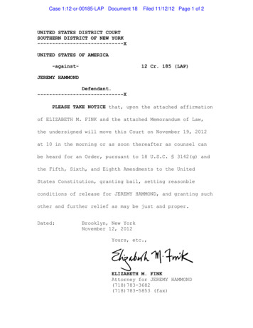
Linear DC Machine – A Simple Example A linear dc machine is about the simplest and easiestto-understand version of a dc machine, yet it operatesaccording to the same principles and exhibits thesame behavior as real generators and motors.r rrF i l Br r reind v B gl(())Smooth frictionless railsUniform-density magnetic fieldBar of conducting metalVB iR eind 0Fnet maSensors & Actuators in MechatronicsElectromechanical Motion FundamentalsK. Craig50
Starting the Linear DC MachineClosing the switch produces a current flow i VBRThe current flow produces a force on the bar given by F i lBThe bar accelerates to the right, producing an inducedvoltage eind as it speeds up.VB e ind This induced voltage reduces the current flow i R()The induced force is thus decreased until eventually F 0. At that point, eind VB and i 0, and the bar moves at F i lBa constant no-load speed.Vvss BBlSensors & Actuators in MechatronicsElectromechanical Motion FundamentalsK. Craig51
The Linear DC Machineas a MotorApply an external loadAssume machine is initially running at no-load SS conditionsA force F load is applied opposite to the direction of motion,which causes a net force F net opposite to the direction ofmotion.The resulting acceleration is negative, so the bar slowsFdown.e ind v l Ba netmVB e ind The voltage eind falls, and so i increases.i RThe induced force F ind increases until, at a lower speed, Find Fload()Find i lBAn amount of electric power equal to eindi is now beingconverted to mechanical power equal to F indv.Sensors & Actuators in MechatronicsElectromechanical Motion FundamentalsK. Craig52
The Linear DC Machineas a GeneratorApply a force in the direction of motionAssume machine is initially running at no-load SS conditionsA force Fapp is applied in the direction of motion; F net is in the direction of motion.FAcceleration is positive, so the bar speeds up.e ind v Bla netmeind VBThe voltage eind increases, and so i increases.i RF FThe induced force F ind increases until, at a higher speed, indapp()Find i lBAn amount of mechanical power equal to F indv is now being converted to electricpower eindi, and the machine is acting a a generator.Sensors & Actuators in MechatronicsElectromechanical Motion FundamentalsK. Craig53
Observations– The same machine acts as both motor and generator. Generator: externally applied forces are in the direction of motion Motor: externally applied forces are opposite to the direction ofmotion– Electrically eind VB, machine acts as a generator eind VB, machine acts as a motor– Whether the machine is a motor or a generator, bothinduced force (motor action) and induced voltage(generator action) are present at all times.– This machine was a generator when it moved rapidly and amotor when it moved more slowly, but whether it was amotor or a generator, it always moved in the samedirection.Sensors & Actuators in MechatronicsElectromechanical Motion FundamentalsK. Craig54
Example Problem A linear dc machine has a battery voltage of 120 V,an internal resistance of 0.3 Ω, and a magnetic fluxdensity of 0.1 T.– What is the machine’s maximum starting current? What isits steady-state velocity at no load?– Suppose that a 30-N force pointing to the right wereapplied to the bar. What would the steady-state speed be?How much power would the bar be producing orconsuming? How much power would the battery beproducing or consuming? Explain the difference betweenthese two figures. Is this machine acting as a motor or as agenerator?Sensors & Actuators in MechatronicsElectromechanical Motion FundamentalsK. Craig55
– Now suppose a 30-N force pointing to the left were appliedto the bar. What would the new steady-state speed be? Isthis machine a motor or a generator now?– Assume that a force pointing to the left is applied to thebar. Calculate the speed of the bar as a function of the forcefor values from 0 N to 50 N in 10-N steps. Plot the velocityof the bar versus the applied force.– Assume that the bar is unloaded and that it suddenly runsinto a region where the magnetic field is weakened to 0.08T. How fast will the bar go now?Sensors & Actuators in MechatronicsElectromechanical Motion FundamentalsK. Craig56
Example ProblemStarting ConditionsOperating as a GeneratorOperating as a MotorSensors & Actuators in MechatronicsElectromechanical Motion FundamentalsK. Craig57
Stationary Magnetically Coupled Circuits Magnetically-coupled electric circuits are central tothe operation of transformers and electromechanicalmotion devices. In transformers, stationary circuits are magneticallycoupled for the purpose of changing the voltage andcurrent levels. In electromechanical motion devices, circuits inrelative motion are magnetically coupled for thepurpose of transferring energy between themechanical and electrical systems.Sensors & Actuators in MechatronicsElectromechanical Motion FundamentalsK. Craig58
Goal:– Establish the equations that describe the behavior ofmagnetically coupled circuits– Express the equations in a form convenient for analysis C
If free to rotate, permanent magnets point approximately north-south. Like poles repel, unlike poles attract. Permanent magnets attract some things (like iron and steel), but not others (like wood and glass). Magnetic forces attract only magnetic materials. Ma