Transcription
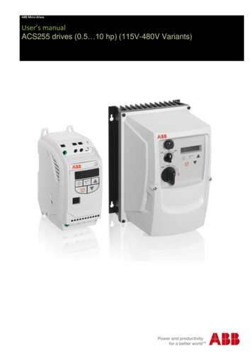
1ABB Micro drivesUser’s manualACS255 drives (0.5 10 hp) (115V-480V Variants)
ABB Micro drivesList of related manualsOption manuals and guidesCode (English)ACS255 user’s manual for 600V variants3AXD10000528265You can find manuals and other product documents in PDF format on the Internet. Go to www.abb.com/drives and select Document Library.You can browse the library or enter selection criteria, for example a document code, in the search field. For manuals not available in theDocument library, contact your local ABB representative
3ACS255 drives0.5 10 hpUser’s manual3AXD10000528266 Rev BENEFFECTIVE: 2017-06-29 2016 ABB Oy. All Rights Reserved.
4
51. Table of Contents1.Table of Contents 5ACS255 – IP20 (115V)EASY START-UP GUIDE 7ACS255 – IP66 (115-480V Switched Variants)EASY START-UP GUIDE 8ACS255 – IP66 (115-480V Non-Switched Variants) EASY START-UP GUIDE 92.Safety 112.1.What this chapter contains 112.2.Use of warnings 112.3.Safety in installation and maintenance 112.4.Safety in start-up and operation 123.General Information and Ratings 143.1.Type designation key 143.2.Drive Model Numbers – IP20 153.3.Drive Model Numbers – IP66 154.Mechanical Installation 164.1.General 164.2.Mechanical Dimensions and Mounting – IP20 Open Units 164.3.Guidelines for Enclosure Mounting – IP20 Units 164.4.Mechanical Dimensions – IP66 (Nema 4X) Enclosed Units 174.5.Guidelines for Mounting Enclosed Units 174.6.Gland Plate and Lock Out 184.7.Removing the Terminal Cover 185.Power Wiring 195.1.Grounding the Drive 195.2.Wiring Precautions 205.3.Connection Diagram 215.4.Drive & Motor Connections 225.5.Motor Terminal Box Connections 225.6.Using the REV/Off/FWD Selector Switch (IP66 Switched Version Only) 236.Control Wiring 246.1.Control Terminal Connections 246.2.RJ45 Data Connection 247.Operation 257.1.Managing the Keypad 257.2.Changing Parameters 257.3.Resetting to Factory Default Settings 258.8.1.Quick Start-up and Control 26Quick Start-up Terminal Control 26
68.2.9.Quick Start-up Keypad Control 27Application Macros 289.1.Overview of macros 2810. Parameters 3110.1.Parameter Structure 3110.2.Parameters in the Short parameter mode 3210.3.Read Only Status parameters 3410.4.Parameters in the Long parameter mode 3610.5.Adjusting the Voltage / Frequency (V/f) characteristics 4110.6.Motor Thermistor Connection 4110.7.Preventing un-authorised parameter editing. 4211. Modbus RTU Communications 4411.1.Introduction 4411.2.Modbus RTU Specification 4411.3.RJ45 Connector Configuration 4411.4.Modbus Telegram Structure 4411.5.Modbus Register Map 4411.6.Modbus Parameter Register Map 4512. Technical Data 4612.1.Environmental 4612.2.Rating Tables 4612.3.Overload 4712.4.Additional Information for UL Compliance 4712.5.Derating Information 4712.6.Mains Line input Reactors 4813. Trouble Shooting 5013.1.Fault Code Messages 50
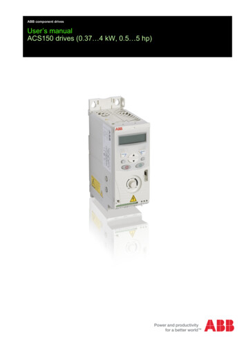
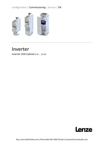
7ACS255 – IP20 (115V)AC SupplyVoltage(50/60Hz)EarthL1 L2 L3L NEASY START-UP GUIDESupply Voltage :-115 Volts1 PhaseCheck the drive rating information on page 46Fuses, Cable Sizes :Fuses-Fuse Rating recommendation values given on page 46Cable size recommendation values given on page 46Always follow local and national codes of practiceKeypad operation can be found in sections 7 and 8Control Terminals :Based on the default, out of box settings –-Connect a Start/Stop switch between terminals 1& 2Close the switch to startOpen the switch to stop-To vary the speed from minimum (0Hz) to maximum(60Hz) Connect a 10kΩ potentiometer to terminals 5,6& 7.125Stop - Run6710kΩSpeed PotMotor Cable Sizes-Cable size recommendation values given on page 46Motor ConnectionsM-Check for Star or Delta connection according to themotor voltage rating (See page 22)Motor Nameplate Details-Enter the motor rated voltage in parameter 9905Enter the motor rated current in parameter 9906Enter the motor rated frequency in parameter 9907
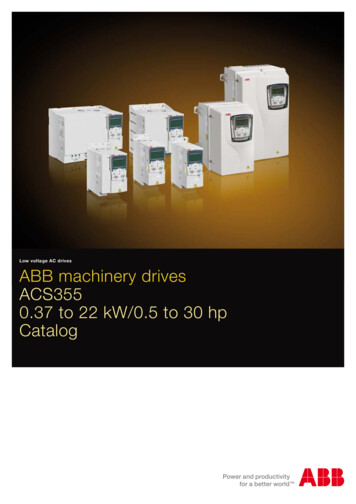
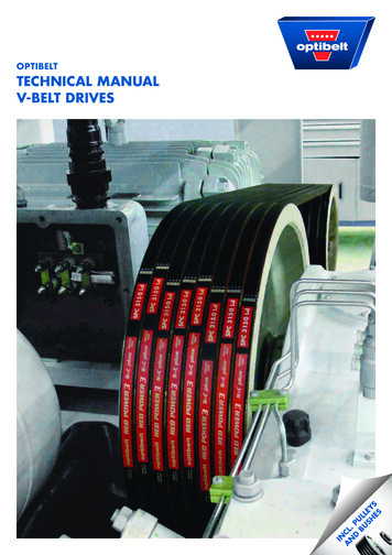
8ACS255 – IP66 (115-480V Switched Variants)EASY START-UP GUIDELocal Speed PotentiometerThe local speed potentiometer will adjustthe output frequency from minimum(Parameter 2007, default setting 0Hz) tomaximum (Parameter 2008, defaultsetting 60Hz)Mechanical Mounting-Information can befound on page 17Run Reverse / Off / Run Forward SwitchWith the factory parameter settings, thisswitch allows the drive to be started inthe forward and reverse operatingdirections. Alternative switch functionscan be programmed, such asLocal/Remote, hand / Off/ Auto, see page23.Keypad operation can befound in section 7 and 8Local Powerdisconnect with lockout provisionMotor Cable Sizes-Fuses, Cable Sizes :-Fuse Rating recommendation values given on page 46Cable size recommendation values given on page 46Always follow local and national codes of practice.Cable sizerecommendation valuesgiven on page 46FusesSupply Voltage :Motor Connections--115, 230, 400, 480 Volts1 or 3 PhaseCheck the drive ratinginformation on page 46Check for Star or Delta connectionaccording to the motor voltage rating(See page 22)Motor Nameplate Details-Enter the motor rated voltage inparameter 9905Enter the motor rated current inparameter 9906Enter the motor rated frequency inparameter 9907
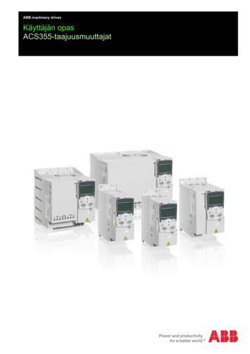
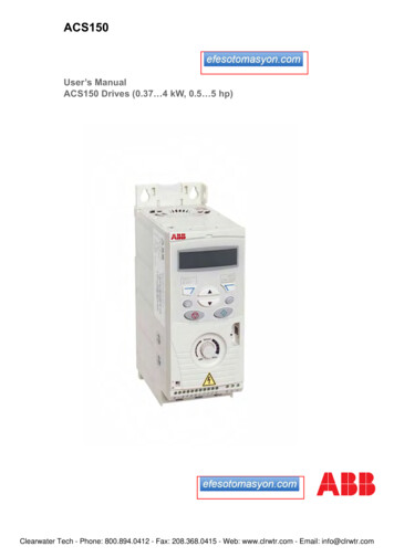
9ACS255 – IP66 (115-480V Non-Switched Variants)EASY START-UP GUIDEMechanical Mounting-Information can be foundon page 17Keypad operation can befound in sections 7 and 8Motor Cable SizesFuses, Cable Sizes :Fuses, Cable Sizes :Fuse Rating recommendation values given on page 46- recommendationCheck the drive ratingCable sizevalues given on page 46informationon page codes46Always followlocal and nationalof practice-Cable sizerecommendation valuesgiven on page 46FusesSupply Voltage :Motor Connections--115, 230, 400, 480 Volts1 or 3 PhaseCheck the drive ratinginformation on page 46Check for Star or Delta connectionaccording to the motor voltagerating (See page 22)Motor Nameplate Details-Enter the motor rated voltage inparameter 9905Enter the motor rated current inparameter 9906Enter the motor rated frequency inparameter 9907
Declaration of ConformityThe manufacturer hereby states that the ACS255 product range conforms to the relevant safety provisions of the following council directives:2014/30/EU (EMC) and 2014/35/EU (LVD)2011/65/EU (RoHS)EN 61800-5-1: 2007Adjustable speed electrical power drive systems. Safety requirements. Electrical, thermal and energy.EN 61800-3 2nd Ed: 2004/ A1:2012EN 55011: 2007Adjustable speed electrical power drive systems. EMC requirements and specific test methodsLimits and Methods of measurement of radio disturbance characteristics of industrial, scientific andmedical (ISM) radio-frequency equipment (EMC)Specifications for degrees of protection provided by enclosuresEN60529 : 1992Electromagnetic CompatibilityAll drives are designed with high standards of EMC in mind.It is the responsibility of the installer to ensure that the equipment or system into which the product is incorporated complies with the EMClegislation of the country of use. Within the European Union, equipment into which this product is incorporated must comply with the EMCDirective 2004/108/EC. When using an ACS255 with an external filter, compliance with the following EMC Categories, as defined by EN618003:2004 can be achieved:Drive Type / RatingFirst Environment Category C1ACS255- U NoteUse External EMC FilterEMC CategoryFirst Environment Category C2Use External EMC FilterSecond Environment Category C3Use External EMC FilterCompliance with EMC standards is dependent on a number of factors including the environment in which the drive is installed,motor switching frequency, motor, cable lengths and installation methods adopted.For shielded motor cable lengths greater than 100m and up to 200m, an output dv/dt filter must be used (please refer tohttp://www.abb.com/ProductGuide for further details)All rights reserved. No part of this User Guide may be reproduced or transmitted in any form or by any means, electrical or mechanicalincluding photocopying, recording or by any information storage or retrieval system without permission in writing from the publisher.ABB Drives Ltd 2016The manufacturer accepts no liability for any damage caused during or resulting from transport, receipt of delivery, installation orcommissioning. The manufacturer also accepts no liability for damage or consequences resulting from inappropriate, negligent or incorrectinstallation, incorrect adjustment of the operating parameters of the drive, incorrect matching of the drive to the motor, incorrect installation,unacceptable dust, moisture, corrosive substances, excessive vibration or ambient temperatures outside of the design specification.The contents of this User Guide are believed to be correct at the time of printing. In the interest of a commitment to a policy of continuousimprovement, the manufacturer reserves the right to change the specification of the product or its performance or the contents of the UserGuide without notice.This User Guide is for use with version 2.0x Software.User Guide Revision BThis user guide is the “original instructions” document. All non-English versions are translations of the “original instructions”.The manufacturer adopts a policy of continuous improvement and whilst every effort has been made to provide accurate and up to dateinformation, the information contained in this User Guide should be used for guidance purposes only and does not form the part of anycontract.
112. Safety2.1. What this chapter containsThis chapter contains the safety instructions which you must follow when installing, operating and servicing the drive. Ifignored, physical injury or death may follow, or damage may occur to the drive, motor or driven equipment. Read thesafety instructions before you work on the unit.2.2. Use of warningsWarnings caution you about conditions which can result in serious injury or death and/or damage to the equipment andadvice on how to avoid the danger. The following warning symbols are used in this manual:Electricity warning warns of hazards from electricity which can cause physical injury and/or damage tothe equipment.General warning warns about conditions, other than those caused by electricity, which ca
1 ABB Micro drives Users manual ACS255 drives (0.5 10 hp) (115V-480V Variants)