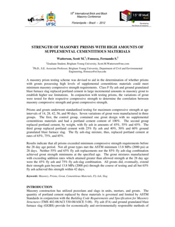
Transcription
TECHNICAL NOTES on Brick Construction 161850 Centennial Park Drive, Reston, Virginia 20191 www.gobrick.com 703-620-0010March2008Fire Resistance of Brick MasonryAbstract: This Technical Note presents information about the fire resistance of brick masonry assemblies in loadbearing andveneer applications. Fire resistance ratings of several brick masonry wall assemblies tested using ASTM E119 procedures arelisted. For untested wall assemblies, procedures are presented for calculating a fire resistance rating.Key Words: balanced design, building codes, equivalent thickness, fire, fire resistance period, fire resistance rating, fire test.SUMMARY OF RECOMMENDATIONS:Fire Resistance RequirementsAssembly with Calculated Fire Resistance RatingAssembly with Tested Fire Resistance RatingConstruction Details Use the building code to determine the fire resistancerating required for separations, corridors, exterior wallsand other building features Use fire control systems, compartmentalization of spaceor other “balanced design” approaches to lower requiredfire resistance ratings Determine whether fire resistance is needed for one sideor two sides of fire exposure Use wall construction prescribed by the building code ortesting agency to achieve fire resistance rating For wall construction not prescribed by the building code,include reference for test results in design documents Determine minimum equivalent thickness required ofbrick unit from tables in the building code or ACI 216.1/TMS 0216 [Ref. 5] Specify brick standard, brick size and void area to meetthe minimum equivalent thickness requirements For multi-wythe masonry walls, determine contributionsfrom other wall components such as concrete, concretemasonry, air spaces and plaster Where assemblies with a fire resistance rating aresupported by other assemblies, specify that the supportassembly have an equal or greater fire resistance rating Seal penetrations through assemblies with a fireresistance rating with appropriate sealants or details tomaintain fire resistance ratingINTRODUCTIONBuilding codes and other local ordinances require critical building components to have a certain level of fireresistance to protect occupants and to allow a means of escape. Several factors contribute to the level of fireresistance required of a wall, floor or roof assembly, including whether combustible (wood) or noncombustible(steel, concrete and masonry) construction is used. Other factors include the building’s use, floor area and height,the location of the assembly, and whether a fire suppression system such as stand pipes or sprinklers is installed.DefinitionsFire Resistance. The property of a building element, component or assembly that prevents or retards the passageof excessive heat, hot gases or flames under conditions of use.Fire Resistance Period. A duration of time determined by a fire test or method based on a fire test that a buildingelement, component or assembly maintains the ability to confine a fire, continues to perform a given structuralfunction or both.Fire Resistance Rating. A duration of time not exceeding 4 hours (as established by the building code) that abuilding element, component or assembly maintains the ability to confine a fire, continues to perform a givenstructural function or both. A legal term defined in building codes for various types of construction and occupancies.A fire resistance rating is based on a fire resistance period and usually given in half-hour or hourly increments. Asan example, a wall with a fire resistance period of 2 hours and 25 minutes may only attain a fire resistance ratingof 2 hours. It is also referred to as a fire rating, fire resistance classification or hourly rating. 2008 Brick Industry Association, Reston, VirginiaPage 1 of 16
Determining a Fire Resistance RatingTraditionally, a fire resistance rating has been established by testing. The most common test method used is ASTME119, Standard Test Methods for Fire Tests of Building Construction and Materials [Ref. 3]. In this test, a sample ofthe wall must perform successfully during exposure to a controlled fire for the specified period of time, followed bythe impact of a stream of water from a hose.This standard test, along with other ASTM fire test standards, is used to measure and describe the response ofmaterials, products or assemblies to heat and flame under controlled conditions, but does not by itself replicateactual fire conditions in a building. Rather, the intent of the test is to provide comparative performance to specificfire-test conditions during the period of exposure. Further, the test is valid only for the specific assembly tested.Fire testing is expensive because each specific assembly must be tested by constructing a large specimen,placing multiple monitoring devices on that specimen and subjecting the specimen to both a fire and a hosestream. As a result, a calculated fire resistance method developed jointly by The Masonry Society and theAmerican Concrete Institute and based on past ASTM E119 tests has largely replaced further fire resistancetesting for masonry and concrete materials [Ref. 5].FIRE RESISTANCE TESTING2400ASTM E119 Test e, Deg. CTemperature, Deg. FThe test methods described in ASTM E119 areapplicable to assemblies of masonry units and tocomposite assemblies of structural materials forbuildings, including bearing and other walls andpartitions, columns, girders, beams, slabs andcomposite slab and beam assemblies for floors androofs.12000012345Time, hours678When fire testing a wall assembly according to ASTMFigure 1E119, a sample of the wall is built using the materialsTime-Temperature Curve for ASTM Standard E119and details of the assembly to be used in construction.The specimen is then subjected to a controlled fireuntil a failure occurs (termination point is reached) or a designated extent of time passes. ASTM E119 requires thatthe air temperature at a distance of 6 in. (152 mm) from the exposed (fire) side of the specimen conform to thestandard time-temperature curve, as shown in Figure 1.Wall Specimens. The area exposed to the fire must be at least 100 sq ft (9.3 m2) with no dimension less than 9 ft(2.7 m). Non-bearing walls and partitions are restrained at all four sides, but bearing walls and partitions are notrestrained at the vertical edges. Nine thermocouples are placed on the side of the wall unexposed to the fire tomeasure temperature rise.Protected Steel Column Specimens. If the fire resistant material protecting the column is structural, the columnspecimen must be at least 9 ft (2.7 m) tall, and acceptance is based on its ability to carry an axial load for theduration of the fire test. If the fire resistant material is not structural, the minimum column height is 8 ft (2.4 m), andacceptance is based on temperature rise on the surface of the column. Temperature rise is measured by placing aminimum of three thermocouples on the column surface (behind the fire resistant material) at each of four levels.Hose Stream Test. For most fire resistance ratings ASTM E119 requires that walls be subjected to both a fireendurance test and a hose stream test. The hose stream test subjects a specimen to impact, erosion and coolingeffects over the entire surface area that has been exposed to the fire. The procedure stipulates nozzle size,distance, duration of application and water pressure at the base of the nozzle. Some of these requirements varywith the fire resistance rating. The hose stream test may be performed on a duplicate wall specimen that hasbeen subjected to a fire endurance test for one-half of the period determined by the fire test (but not more than 1hour); or the hose stream test may be performed on the wall specimen immediately after the full duration of fireexposure. The latter option is typically used to test brick walls because the test termination point is almost always atemperature rise rather than a failure by passage of hot gases or collapse where there is a degradation of the brickwythe from the hose stream test. Some other materials rely on the duplicate specimen to meet certain fire ratings.www.gobrick.com Brick Industry Association TN 16 Fire Resistance of Brick Masonry Page 2 of 16
Loading. Throughout the fire endurance and hose stream tests, a superimposed load is applied to bearingspecimens. The applied load is required to be the maximum load condition allowed by nationally recognizedstructural design criteria or by limited design criteria for a reduced load.Columns are loaded to simulate the maximum load condition allowed by nationally recognized structural designcriteria or by limited design criteria for a reduced load. The column is then subjected to the standard fire on allsides. Where the fire protection is not designed to carry loads, an alternate test method in which the column is notloaded may be used.Conditions of AcceptanceThe number of criteria considered as termination points for a fire test on an assembly depends on whether theassembly is loadbearing or not.Non-Bearing Walls and Partitions. The test is successful and a fire resistance rating is assigned to theconstruction if all of the following criteria are met:1. The assembly withstands the fire endurance test without passage of flame or gases hot enough toignite cotton waste for a period equal to that for which classification is desired.2. The assembly withstands the fire endurance test without passage of flame and the hose stream testwithout passage of water from the hose stream. If an opening develops in the wall specimen thatpermits a projection of water beyond the surface of the unexposed side during the hose stream test,the assembly is considered to have failed the test.3. The average rise in temperature of nine thermocouples on the unexposed surface is not morethan 250 ºF (139 ºC) above their average initial temperature, and the temperature rise of a singlethermocouple is not more than 325 ºF (181 ºC) above its initial temperature.Bearing Walls. The conditions of acceptance for bearing walls are the same as for non-bearing walls andpartitions (above), with the following addition:4. The specimen must also sustain the applied load during the fire endurance and hose stream tests.The first three criteria relate to providing a barrier against the spread of fire by penetration of the assembly; thefourth relates to structural integrity. The termination point for fire tests of brick masonry walls is almost invariablydue to temperature rise (heat transmission) of the unexposed surface. Brick masonry walls successfully withstandthe load during the fire endurance test and the hose stream test conducted immediately after the wall has beensubjected to the fire exposure. This structural integrity of brick masonry walls is attested to in many fires where themasonry walls have remained standing when other parts of the building have been destroyed or consumed duringthe fire.Columns. Columns with integral structural fireproofing are assigned a fire resistance rating when they supportthe superimposed load during the fire endurance test. For columns with fireproofing not designed to carry loads,a fire resistance rating is assigned when the average temperature rise does not exceed 1000 ºF (556 ºC) or themaximum temperature rise does not exceed 1200 ºF (667 ºC) at any one point.FIRE RESISTANCE RATINGS OF WALLSThere are several sources of fire resistance ratings for brick masonry assemblies that will typically satisfythe requirements of the local building official. Model building codes contain results based on testing. Privatelaboratories report fire test results. Individual associations and companies sponsor fire tests and make the resultsavailable.www.gobrick.com Brick Industry Association TN 16 Fire Resistance of Brick Masonry Page 3 of 16
Building CodesTable 1 presents fire resistance ratings for various masonry wall assemblies, as taken from the 2006 InternationalBuilding Code Table 720.1(2) [Ref. 1]. Note that for item numbers 1.1-1 through 1.1-3, 1-2.1, and 2-1.1 through2-1.2, the required thickness of clay brick masonry is the equivalent thickness, i.e. the thickness is the volumeof clay in a unit divided by the face area. Table 2 presents fire resistance ratings for brick veneer/steel stud wallassemblies as taken from Table 721.4.1(2) of the same code.TABLE 1Fire Resistance Ratings (Periods) for Various Walls and PartitionsMaterialItemNumberConstructionMinimum FinishedThickness,Face-to-Face, in. (mm)4 hr1. Brick of clayor shale22. Combinationof clay brickand loadbearinghollow clay tile215. Exterior orinterior walls4,5,63 hr2 hr1 hr1-1.1Solid brick of clay or shale16.04.9(152) (124)3.8(97)2.7(69)1-1.2Hollow brick, not filled5.04.3(127) (109)3.4(86)2.3(58)1-1.3Hollow brick unit wall, grouted solid or filled with perlite vermiculiteor expanded shale aggregate6.65.54.4(168) (140) (112)3.0(76)1-2.14 in. (102 mm) nominal thick units at least 75 percent solid backedwith hat-shaped metal furring channel ¾ in. (76 mm) thick formedfrom 0.021 in. (0.53 mm) sheet metal attached to the brick wall at24 in. (610 mm) o.c. with approved fasteners, and ½ in. (12.7 mm)Type X gypsum wallboard attached to the metal furring strips with1 in. (25.4 mm) long Type S screws spaced at 8 in. (203 mm) o.c.——53(127)—2-1.14 in. (102 mm) solid brick and 4 in. (102 mm) tile (at least40 percent solid)—8(203)——2-1.24 in. (102 mm) solid brick and 8 in. (203 mm) tile (at least40 percent solid)12(305)—————10(254)—15-1.572¼ 3¾ in. (57 95 mm) clay face brick with cored holes over½ in. (12.7 mm) gypsum sheathing on exterior surface of 2 4 in.(51 102 mm) wood studs at 16 in. (406 mm) o.c. and two layers⅝ in. (15.9 mm) Type X gypsum wallboard on interior surface.Sheathing placed horizontally or vertically with vertical joints overstuds nailed 6 in. (152 mm) on center with 1¾ in. (44 mm) byNo. 11 gage by 7 16 in. (11.1 mm) head galvanized nails. Innerlayer of wallboard placed horizontally or vertically and nailed8 in. (203 mm) on center with 6d cooler or wallboard nails. Outerlayer of wallboard placed horizontally or vertically and nailed8 in. (203 mm) on center with 8d cooler or wallboard nails. Alljoints staggered with vertical joints over studs. Outer layer jointstaped and finished with compound. Nail heads covered with jointcompound. 0.035 in. (0.89 mm) (No. 20 galvanized sheet gage)corrugated galvanized steel wall ties ¾ 6⅝ in. (19.1 168 mm)attached to each stud with two 8d cooler or wallboard nails everysixth course of bricks.1. For units in which the net cross-sectional area of cored brick in any plane parallel to the surface containing the cores is at least 75 percent ofthe gross cross-sectional area measured in the same plane.2. Thickness shown for brick and clay tile are nominal thicknesses unless plastered, in which case thicknesses are net. Thickness shownfor clay masonry is equivalent thickness defined by Equation 3. Where all cells are solid grouted or filled with silicone-treated perlite loose-fillinsulation; vermiculite loose-fill insulation; or expanded clay, shale or slate lightweight aggregate, the equivalent thickness shall be the thicknessof the brick using specified dimensions. Equivalent thickness may also include the thickness of applied plaster and lath or gypsum wallboard,where specified.3. Shall be used for non-bearing purposes only.4. Staples with equivalent holding power and penetration shall be permitted to be used as alternate fasteners to nails for attachment to woodframing.5. For all of the construction with gypsum wallboard described in this table, gypsum base for veneer plaster of the same size, thickness andcore type shall be permitted to be substituted for gypsum wallboard, provided attachment is identical to that specified for the wallboard, and thejoints on the face layer are reinforced and the entire surface is covered with a minimum of 1 16 in. (1.6 mm) gypsum veneer plaster.6. For properties of cooler or wallboard nails, see ASTM C514, ASTM C547 or ASTM F1667.7. The design stress of studs shall be reduced to 78 percent of allowable F′c with the maximum not greater than 78 percent of the calculatedstress with studs having a slenderness ratio l/d of 33.www.gobrick.com Brick Industry Association TN 16 Fire Resistance of Brick Masonry Page 4 of 16
TABLE 2Fire Resistance Ratings for Brick Veneer/Steel Stud AssembliesPlasterSideExposed(hours)BrickFaced SideExposed(hours)Outside facing of steel studs:½ in. (12.7 mm) wood fiberboard sheathing next to studs, ¾ in. (19.1 mm) air space formedwith ¾ 1⅝ in. (19.1 41 mm) wood strips placed over the fiberboard and secured to thestuds; metal or wire lath nailed to such strips, 3¾ in. (95 mm) brick veneer held in place byfilling ¾ in. (19.1 mm) air space between the brick and lath with mortar.Inside facing of studs:¾ in. (19.1 mm) unsanded gypsum plaster on metal or wire lath attached to 5 16 in. (7.9 mm)wood strips secured to edges of the studs.1.54Outside facing of steel studs:1 in. (25.4 mm) insulation board sheathing attached to studs, 1 in. (25.4 mm) air space, and3¾ in. (95 mm) brick veneer attached to steel frame with metal ties every fifth course.Inside facing of studs:⅞ in. (22.2 mm) sanded gypsum plaster (1:2 mix) applied on metal or wire lath attacheddirectly to the studs.1.54Same as above except use ⅞ in. (22.2 mm) vermiculite — gypsum plaster — or 1 in. (25.4 mm)sanded gypsum plaster (1:2 mix) applied to metal or wire.24Outside facing of steel studs:½ in. (12.7 mm) gypsum sheathing board, attached to studs, and 3¾ in. (95 mm) brick veneerattached to steel frame with metal ties every fifth course.Inside facing of studs:½ in. (12.7 mm) sanded gypsum plaster (1:2 mix) applied to ½ in. (12.7 mm) perforatedgypsum lath securely attached to studs and having strips of metal lath 3 in. (76 mm) wideapplied to all horizontal joints of gypsum lath.24Wall or Partition AssemblyUL ListingsUnderwriters Laboratories is a resource recognized throughout the building industry that has thousands ofpublished fire resistance rated designs and product certifications that appear in the UL Fire Resistance Directory[Ref. 7] and are typically accepted without modification by building officials. The UL certification is based on anassembly complying with the ASTM E119 test, as described previously. The directory lists several masonry wallassemblies with various potential alternates in materials as shown in Table 3.TABLE 3UL Fire Resistance Ratings for Brick Masonry WallsDesignNumberRating1AssemblyBrick Veneer/Wood Stud, LoadbearingU3022 hr (2) layers ⅝ in. (15.9 mm) thick gypsum wallboard or nominal 3 32 in. (2.4 mm) thick gypsumveneer plaster on Classified veneer baseboard (1) layer ½ in. (12.7 mm) thick exterior gypsum sheathing 1 (25.4 mm) in. (51 102 mm) air space nominal 2 4 in. wood studs spaced at 16 in. (406 mm) o.c. nominal 4 in. (102 mm) clay facing brick laid in mortar with ¾ in. (19.1 mm) wide 6⅝ in. 168mm) long 20 MSG corrugated wall ties spaced at 16 in. (406 mm) o.c. each way1. Unless noted otherwise, fire resistance rating applies to both sides of assembly.www.gobrick.com Brick Industry Association TN 16 Fire Resistance of Brick Masonry Page 5 of 16
TABLE 3 (continued)UL Fire Resistance Ratings for Brick Masonry WallsDesignNumberRating1AssemblyBrick Veneer/Wood Stud, Loadbearing (continued)U356U3711 hr (1) layer ⅝ in. (15.9 mm) thick gypsum board nominal 2 4 in. (51 102 mm) wood studs spaced at 16 in. (406 mm) o.c., with 3½ in. (89 mm)thick glass fiber batt or spray applied cellulose insulation 7 16 in. (11.1 mm) min. thick wood structural panels or min. ½ in. (12.7 mm) thick mineral and fiberboards 1 in. (25.4 mm) air space nominal 4 in. (102 mm) brick veneer with corrugated metal wall ties spaced not more than eachsixth course of brick and max. 32 in. (813 mm) o.c. horizontally1 hr (2) layer ⅝ in. (15.9 mm) thick gypsum board nominal 2 4 in. (51 102 mm) wood studs spaced at 16 in. (406 mm) o.c. with min. 3 in.(76 mm) mineral wool batt insulation (1) layer ⅝ in. (15.9 mm) thick gypsum board 1 in. (25.4 mm) air space nominal 4 in. (102 mm) brick veneer with corrugated metal wall ties attached with screws andspaced not more than each fourth course and a max. 24 in. (610 mm) o.c. horizontallyBrick Veneer/Steel Stud, LoadbearingU418U424U42545 min1 hr2 hr (45 min): (1) layer ⅝ in. (15.9 mm) thick gypsum wallboard(1 hr): (2) layers ½ in. (12.7 mm) thick gypsum wallboard(2 hr): (3) layers ½ in. (12.7 mm) thick gypsum wallboard 3½ or 5½ in., (89 or 140 mm) 18 gage, steel studs, spaced at 24 in. (610 mm) o.c., with 3½ in.(89 mm) thick glass fiber batt insulation (1) layer ½ in. (12.7 mm) thick exterior gypsum sheathing 1 in. (25.4 mm) air space 4 in. (102 mm) nominal clay facing brick laid in mortar with metal ties at 24 in. (610 mm) o.c.horizontally and 16 in. (406 mm) o.c. vertically45 min1 hr1½ hr2 hr (45 min): (1) layer ⅝ in. (15.9 mm) thick gypsum wallboard(1 hr): (2) layers ½ in. (12.7 mm) thick gypsum wallboard(1½ hr): (2) layers ⅝ in. (15.9 mm) thick gypsum wallboard(2 hr): (3) layers ½ in. (12.7 mm) or (2) layers ¾ in. (19.1 mm) thick gypsum wallboard 3½ in. (89 mm), 20 gage steel studs, spaced up to 24 in. (610 mm) o.c., with 3½ in. (89 mm) thickglass fiber or mineral wool batt or blanket insulation (1) layer ½ or ⅝ in. (12.7 or 15.9 mm) thick exterior gypsum sheathing Air space thickness not specified 3¾ in. (95 mm) min. brick veneer with corrugated metal wall ties attached to each stud with steelscrews, not more than each sixth course of brick45 min1 hr1½ hr2 hr (45 min): (1) layer ⅝ in. (15.9 mm) thick gypsum wallboard(1 hr): (2) layers ½ in. (12.7 mm) thick gypsum wallboard(1½ hr): (2) layers ⅝ in. (15.9 mm) thick gypsum wallboard(2 hr): (3) layers ½ in. (12.7 mm) or (2) layers ¾ in. (19.1 mm) thick gypsum wallboard 3½ in. (89 mm), 20 gage steel studs, spaced up to 24 in. (610 mm) o.c., with 3½ in. (89 mm) thickglass fiber or mineral wool batt or blanket insulation (1) layer ½ or ⅝ in. (12.7 or 15.9 mm) thick exterior gypsum sheathing Air space thickness not specified 3¾ in. (95 mm) brick veneer with corrugated metal wall ties attached to each stud with steelscrews, not more than each sixth course of brick1. Unless noted otherwise, fire resistance rating applies to both sides of assembly.www.gobrick.com Brick Industry Association TN 16 Fire Resistance of Brick Masonry Page 6 of 16
TABLE 3 (continued)UL Fire Resistance Ratings for Brick Masonry WallsDesignNumberRating1AssemblyBrick Veneer/Steel Stud, Loadbearing (continued)V434V454V4581 hr (1) layer ⅝ in. (15.9 mm) thick gypsum wallboard 3½ in. (89 mm), 20 gage, steel studs with max. spacing at 24 in. (610 mm) o.c., with 3½ in.(89 mm) thick glass fiber batt insulation 2 in. (51 mm) max. thick foamed plastic 1 in. (25.4 mm) min. air space 4 in. (102 mm) nominal brick veneer with wall anchor ties attached to studs at max. 24 in.(610 mm) o.c.1 hr (1) layer ⅝ in. (15.9 mm) thick gypsum wallboard 3½ in. (89 mm), 20 gage, steel studs at max. spacing of 24 in. (610 mm) o.c. (1) layer ⅝ in. (15.9 mm) thick gypsum wallboard 4 in. (102 mm) max. thick rigid polystyrene insulation 1 in. (25.4 mm) min. air space 4 in. (102 mm) nominal brick veneer with wall anchor ties attached to studs at max. 24 in.(610 mm) o.c.45 min (1) layer ⅝ in. (15.9 mm) thick gypsum wallboard bearing UL Classification Mark 3⅝ in. (92 mm) 18 gage steel studs at max. spacing of 24 in. (610 mm) o.c. with nominal 3.5 pcfmineral wool batt (1) layer ⅝ in. (15.9 mm) thick gypsum wallboard 1 in. (25.4 mm) min. air space 3¾ in. (95 mm) min. thick brick veneer with corrugated metal wall ties attached to each stud withsteel screws, not more than each sixth course of brickBrick Veneer/Steel Stud, Non-LoadbearingV4143 hr,interior1 hr,exterior (1) layer ⅝ in. (15.9 mm) thick gypsum wallboard 3⅝ in. (92 mm) wide, 1⅝ in. (41 mm) legs, 20 gage steel studs, spaced 16 in. (406 mm) o.c.,studs cut ¾ in. (19.1 mm) less than assembly height 2 in. (51 mm) thick foamed plastic (rigid insulation) 2 in. (51 mm) air space 4 in. (102 mm) nominal clay facing brick laid in mortar with metal ties at 16 in. (406 mm) o.c. max.each wayBrick/Concrete Masonry, LoadbearingU9024 hr 4 in. (102 mm) nominal loadbearing concrete masonry unit laid with full mortar beds and with9 gage joint reinforcement at 16 in. (406 mm) o.c. vertically min. 1 in. (25.4 mm) air space with up to 4 in. (102 mm) foamed plastic (rigid insulation) as option ¾ in. (19.1 mm) wide, 7 in. (178 mm) long, 26 gage corrugated metal ties spaced at 8 in.(203 mm) o.c. horizontally and 16 in. (406 mm) o.c. vertically or truss or ladder type jointreinforcement of 9 gage wire for full width of wall assembly, cross wires at 16 in. (406 mm) o.c.,spaced at 16 in. (406 mm) o.c. vertically 4 in. (102 mm) nominal clay facing brick laid in mortar1. Unless noted otherwise, fire resistance rating applies to both sides of assembly.OtherIn addition to assemblies listed above, there are several other assemblies previously tested with results publishedin past building codes or other publications. A selection of these appears in Table 4.www.gobrick.com Brick Industry Association TN 16 Fire Resistance of Brick Masonry Page 7 of 16
TABLE 4Fire Resistance Ratings for Other Brick Masonry Wall Assemblies1TestRating2AssemblyBrick Veneer/Wood Stud1231 hr (1) layer ½ in. (12.7 mm) thick gypsum wallboard 2 4 in. (51 102 mm) wood studs spaced at 16 in. (406 mm) o.c. with 3½ in. (89 mm) glass fiber battinsulation between studs (1) layer ½ in. (12.7 mm) thick wood fiberboard sheathing (1) layer No. 15 asphalt felt paper 1 in. (25.4 mm) air space 3½ in. (89 mm) actual width hollow clay brick with void area of 34.5% (equivalent thickness of 2.3in. (58 mm)), laid in mortar with ⅞ in. (22.2 mm) wide, 22 gage corrugated wall ties spaced at 24 in.(610 mm) o.c. horizontally and 16 in. (406 mm) o.c. vertically1 hr (1) layer ½ in. (12.7 mm) thick gypsum wallboard 2 4 in. (51 102 mm) wood studs spaced at 16 in. (406 mm) o.c. with 3½ in. (89 mm) glass fiber battinsulation between studs (1) layer ½ in. (12.7 mm) thick wood fiberboard sheathing (1) layer No. 15 asphalt felt paper 1 in. (25.4 mm) air space 2⅞ in. (73 mm) actual width hollow clay brick with void area of 36% (equivalent thickness of 1.8 in.(46 mm)), laid in mortar with ⅞ in. (22.2 mm) wide, 22 gage corrugated wall ties spaced at 24 in.(610 mm) o.c. horizontally and 16 in. (406 mm) o.c. vertically1 hr (1) layer ½ in. (12.7 mm) thick gypsum wallboard 2 4 in. (51 102 mm) wood studs spaced at 16 in. (406 mm) o.c. with 3½ in. (89 mm) glass fiber battinsulation between studs (1) layer ½ in. (12.7 mm) thick wood fiberboard sheathing (1) layer No. 15 asphalt felt paper 1 in. (25.4 mm) air space 1¾ in. (44 mm) actual width3 hollow clay brick with void area of 26.9% (equivalent thickness of 1.3in. (32 mm)), laid in mortar with ⅞ in. (22.2 mm) wide, 22 gage corrugated wall ties spaced at 24 in.(610 mm) o.c. horizontally and 16 in. (406 mm) o.c. vertically1. As tested by the Southwest Research Institute [Ref. 4].2. Fire resistance rating applies to brick (exterior) side only. Test stopped at 1 hour.3. Width not in compliance with 2006 IBC veneer requirements; however, complies with 2006 IRC [Ref. 2] veneer requirements.CALCULATED FIRE RESISTANCETheory and DerivationThe extent of fire resistance provided by a clay masonry wall is a function of the wall’s mass or thickness. Thiswell-established fact is based on the results of many fire resistance tests conducted on walls of solid and hollowclay units. During the ASTM E119 fire test, the fire resistance period of clay masonry walls is usually establishedby the temperature rise on the unexposed side of the wall specimen. Few masonry walls have failed due toloading or thermal shock of the hose stream.The method for calculating a fire resistance period is described in NBS BMS 92, Fire-Resistance Classificationsof Building Construction [Ref. 6]. The construction must be similar to others for which the fire resistance periodsare known or of composite construction for which the fire resistance period of each component is known. Thecalculated fire resistance formulas are based on the temperature rise on the unexposed side of the wall.Heat transmission theory states that when a wall made of a given material is exposed to a heat source that maintainsa constant temperature at the surface of the exposed side and the unexposed side is protected against heat loss, theunexposed side will attain a given temperature rise inversely proportional to the square of the wall’s thickness.In the standard fire test, the time required to attain a given temperature rise on the unexposed side will be differentthan when the temperature on the exposed side remains constant. This is because the fire in the standard firetest increases the temperature at the exposed surface of the wall as the test proceeds. Based on fire test datacollected from many fire tests, the following formula has been derived to express the fire resistance period of awall based on its thickness:www.gobrick.com Brick Industry Association TN 16 Fire Resistance of Brick Masonry Page 8 of 16
R (cV)nEq. 1where:R fire resistance period, hrc coefficient depending on the material, design of the wall, and the units of measurement of R and VV volume of solid material per unit area of wall surface, andn exponent depending on the rate of increase of temperature at the exposed face of the wallFor walls of a given material and design, an increase of 50 percent in volume of solid material per unit area ofwall surface results in a 100 percent increase in the fire resistance period. This relationship results in a value of1.7 for n. The
Nine thermocouples are placed on the side of the wall unexposed to the fire to measure temperature rise. Protected Steel Column Specimens. If the fire resistant material protecting the column is structural, the column specimen must be at least 9 ft (2.7 m) tall, and acceptance i