Transcription
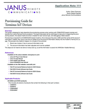
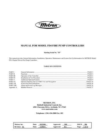
HPCO2Fire Extinguishing SystemThe Janus Fire Systems HPCO2 Fire Extinguishing System utilizes highly pressurized carbon dioxide as the extinguishing medium. Carbon dioxide (CO2) is a dry, inert, non-corrosive fire suppression agent perfectly suited to protect high value assets in normally unoccupied and unoccupiableareas when an electrically non-conductive agent is required and where clean-up of other agents isproblematic. Each system consists of the following components and their associated accessories:1. HPCO2 Storage Components - Storage components consist of the cylinder assembly(s),which contains the liquid CO2 agent, and the cylinder bracket(s), which holds the cylinder assembly securely in place.2. HPCO2 Distribution Components - Distribution components consist of the discharge nozzlesused to introduce the CO2 agent into a protected hazard along with the associated piping system used to connect the nozzles to the cylinder assembly.3. Trim Components - Trim components complete the installation of the HPCO2 system andconsist of discharge flex hose, discharge outlet adapters or check valves, actuation flex hose,connection fittings, solenoid valves, and manual valve actuators.4. Supplemental Components - Supplemental components include the discharge pressureswitch, inline check valves, selector valves, lockout valves, rupture discs, and regulators. Theysupplement the core equipment or complete a specific cylinder configuration.5. Control Panel - This device monitors the condition of the solenoid valve, detectors, warningdevices, and any manual release stations. All electric or electronic devices must connect to thecontrol panel in order to function.6. Early Warning Detection and Alarm Devices - Early warning detection devices coupled withmanual release stations maximize system efficiency while audible and visual alarm devicesalert staff of alarm conditions.Typical High Pressure Carbon Dioxide System LayoutDS1094Revised: 26-Sep-2018 2009 Janus Fire Systems. All rights reserved (4/2009) Janus Fire Systems is a registered trademark of Janus Fire Systems.
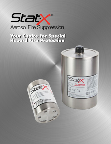
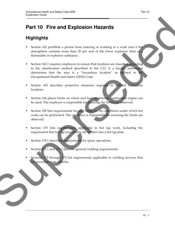
EQUIPMENT DESCRIPTIONThe CO2 agent is stored as a liquid in cylinder assemblies designed specifically for this purposeand pressurized to 850 psi (58.6 bar) at 70 F (21 C). An identification label is affixed to the cylinderbody indicating the empty cylinder weight, filled cylinder weight, fill quantity of CO2, charging pressure, date of fill, and fill station. Except for special temperature conditions, all cylinders are filled totheir specified weight. Winterized cylinders are filled to 90% of their capacity with carbon dioxideand then superpressurized with nitrogen to the remaining full capacity in order to prevent cylinderpressure from dropping below 750 psi (51.7 bar) in extremely cold environments. Cylinders are notpartially filled.CO2 fire extinguishing systems are designed in accordance with National Fire Protection Association (NFPA) 12 - Standard on Carbon Dioxide Extinguishing Systems. CO2 may be used in a totalflooding system where the supply of CO2 is discharged into a normally unoccupied or unoccupiableenclosed space, filling it to a proper concentration. It also may be used for local applications wherethe specially designed CO2 nozzle is arranged to discharge CO2 directly on the burning material.The ambient temperature range for cylinders used in total flooding systems is 0 F to 130 F (-18 Cto 54 C). For cylinders used in local application systems, the ambient temperature range is 32 F to120 F (0 C to 49 C).NominalCylinder Size1EmptyWeightP/NFullWeightHeight (H)Width 5.3310140.662.61590 10.42641 Additional sizes available for special orders.The cylinder assembly is composed of a cylinder, dip tube, and cylinder valve.Cylinder Valve: The automatic release of CO2 is controlled by a forged brass, force differential operatedcylinder valve connected to the neck of the cylinder.Each valve assembly is shipped with an anti-recoilsafety plug installed in the discharge outlet and amanual actuation safety plug installed in the manualactuation connection. Both safety plugs are chainedto the cylinder valve.62.24”Hmm158155.24”1403 mmDip Tube: A rigid dip tube is used in all cylinders toensure liquid discharge.Cylinder: The seamless cylinder is manufactured according to the requirements of the U.S. Department ofTransportation (USDOT) and/or Transport Canada forcompressed gas. The cylinder is designed for mounting in a vertical position only.10.25”Wmm260DS1094Revised: 26-Sep-20188.32”211 mmPage 2 of 20
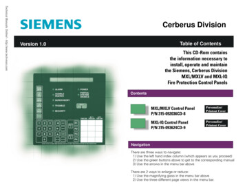
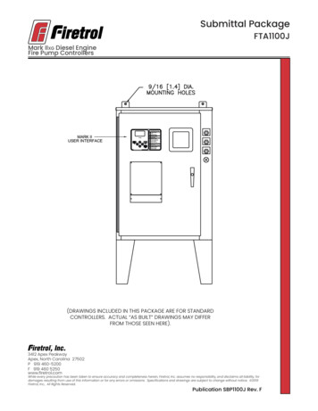
CYLINDER VALVE w/ DIP TUBE ADAPTOR (P/N 19428)Manual Actuation Port(Shown w/ Safety Plug)Discharge Outlet(Shown w/Anti-RecoilSafety Plug)SolenoidActuatorConnectionSolenoidSupport BoltThe cylinder valve has five key features:Manual Actuation Port: A threaded female connection on the top of the primary valve serves as theattachment point for the manual valve actuator. It isshipped with a manual actuation safety plug installed.Solenoid Actuator Connection: A threaded maleconnection serves as the attachment point for the solenoid valve.Solenoid Support Bolt: A bolt located on the side ofthe cylinder valve directly underneath the solenoid actuator connection is used to connect the solenoid support bar to the valve.Manual Actuation Port(Shown w/ Safety Plug)Rupture DiscDischarge Outlet:A 1-1/16” threaded femaleconnection serves as the attachment point for thedischarge outlet adapter or discharge check valve. Itis shipped with an anti-recoil safety plug installed.Rupture Disc: A rupture disc is affixed to the cylinder valve as an emergency relief device in the eventof excessive pressure within the cylinder. Its rupturepoint is in the range of 2,650 to 3,000 psi (182.7 to206.8 bar).Discharge Outlet(Shown w/ Anti-Recoil Safety Plug)Solenoid ActuatorConnectionTRIM COMPONENTSTrim components are required to operate a single HPCO2 cylinder.Manual ActuatorJIC Adapter Nipple(P/N 19588)3/16” (7 mm)ActuationFlex Hose(P/N 19600)Solenoid Valve(P/N 99745 - Standard)Included inSolenoid ValveKitsManual ValveActuator(P/N 19589)Cylinder ActuationConnection Adapter(P/N 19586)Included inSolenoid Valve KitsIncluded inSolenoid ValveKitsIncluded inSolenoid Valve Kit(P/N 19585 - Standard)Rupture DiscShipped withCylinder Valve(Order Replacement Kit 98243)Solenoid JICAdapter Elbow(P/N 19587)Solenoid SupportBracket(P/N 19594)Included inSolenoid ValveKitsSolenoid SupportBracket Bolt(P/N 99750)Included inSolenoid ValveKitsDS1094Revised: 26-Sep-2018Manual ActuationSafety Plug(Shipped withCylinder Valve)Included inSolenoid ValveKitsDischargeOutlet Adapter(P/N 19591)Anti-RecoilSafety Plug(Shipped withCylinder Valve)Page 3 of 20
Discharge Flex Hose3/4” (20 mm)MNPT1/2” (15 mm)MNPTA 22 in (559 mm) discharge flex hose is used to connect the cylinder valve outlet to the system manifold anddischarge piping. The flexible hose allows for temporarymisalignment of the cylinders to ease installation or removal for maintenance. It has a minimum bend radiusof 9.5 inches (241 mm). It is shipped with the dischargeoutlet adapter attached for single cylinder systems (P/N99707) or the discharge outlet check valve attached formultiple cylinder systems (P/N 99706).Swivel1-1/16” ThreadedMale Connection3/4” (20 mm)FNPTDischarge Outlet AdapterA 3/4” (20 mm) FNPT discharge outlet adapter threadsinto the cylinder valve outlet in a single cylinder system. Itfacilitates the attachment of the discharge flex hose to thecylinder valve. The discharge outlet adapter is shippedattached to the discharge flex hose (P/N 99707). Whenmultiple cylinders share a common manifold, a outletcheck valve must be used instead.Discharge Outlet Check Valve3/4” (20 mm)FNPT1-1/16” ThreadedMale ConnectionEmergencyRelease LeverA 3/4” (20 mm) FNPT discharge outlet check valve mustbe threaded into the cylinder valve outlet of each cylindersharing a common manifold in a multiple cylinder system.When threaded into the valve outlet, the check valve isupset allowing direct back pressure from the dischargemanifold to actuate the slave cylinder valves. When acylinder is removed for service, the check valve remainsconnected to the discharge flex hose and functions toprevent the backflow of CO2 agent should accidentaldischarge occur before the cylinder is replaced. Thedischarge outlet check valve is shipped attached to discharge flex hose (P/N 99706).Manual Valve Actuator (P/N 19589)A manual valve actuator attaches to the manual actuationport on top of the primary cylinder valve and provides ameans to manually open the cylinder valve. The manualvalve actuator consists of a brass body, emergency release lever, pressure port, and steel safety ring pin.Ring Pin1/8” (6 mm) FNPTPressure PortTo discharge the cylinder arrangement manually, thering pin is removed and the emergency release leveris pulled. This forces the actuation pin to depress theSchrader valve inside the manual actuation port causingpressure above the cylinder valve piston to be vented.Cylinder pressure then raises the piston to open the cylinder valve.Threaded ValveConnection PortDS1094Revised: 26-Sep-2018Page 4 of 20
Solenoid Valve Kit (See Chart for P/N)The solenoid valve attaches to the primary cylinder valveat the solenoid actuator connection via a cylinder actuation connection adapter and is utilized to automaticallyopen the cylinder valve upon receipt of a signal from thecontrol panel or other source. It has a standard voltage of24 VDC, 10 Watts and enclosure rating NEMA 4X. Orificesize is 1/32 inch (0.8 mm). It has a temperature range of-20 F to 130 F (-29 C to 54 C).CylinderActuationConnectionAdapter(P/N 19586)SolenoidSupport Bracket(P/N 19594)1/2” (15 mm)Conduit Connectorw/ 36” (914 mm)LeadsThe outlet port of the solenoid valve is connected to thepressure port of the manual valve actuator with 3/16” (7mm) flexible hose. When energized, the solenoid valveopens allowing pressure from above the main piston ofthe cylinder valve to vent out through an opening in themanual valve actuator causing the cylinder valve to open.An optional explosion-proof solenoid is available with anenclosure rating NEMA 4x, 7, and 9. Both the standardand explosion-proof solenoids are available in optional120 VAC, 50/60Hz voltage or 220 VAC, 50Hz/240 VAC,60Hz voltage models. All port sizes are identical to thestandard model. Valve kits contain all necessary components to install the solenoid valve.P/NSolenoid Valve Kit1Solenoid ValveVoltageEnclosure Rating195859974524 VDCNEMA 4x997339974424 VDCNEMA 4x, 7, and 99959499617120 VACNEMA 4x9959399616120 VACNEMA 4x, 7, and 99916399165220/240 VACNEMA 4x9916499166220/240 VACNEMA 4x, 7, and 9All Solenoid Valve Kits include Cylinder Actuation Connection Adapter (19586), JIC Adapter Elbow(19587), Flex Hose (19600), JIC Adapter NIpple (19588), Support Bracket (19594), Support Bolt(99750), 2x Screws (99751), and Lock Washer (99746)1JIC Adapter Nipple (P/N 19588)1/8” (6 mm)MNPT1/4” (8 mm)37 Male JICA 1/8” (6 mm) MNPT by 1/4” (8 mm) 37 male JIC adapter nipple is threaded into the pressure port of the manualvalve actuator to facilitate the connection of actuationflex hose. One adapter nipple is shipped as part of eachsolenoid valve kit.1/4” (8 mm)Male JICJIC Adapter Elbow (P/N 19587)1/8” (6 mm)MNPT7.0 in178 mmDS1094Revised: 26-Sep-2018A 1/8” (6 mm) MNPT by 1/4” (8 mm) 37 male JIC adapter elbow is threaded into the outlet of the solenoid valveto facilitate the connection of flexible hose. One adapterelbow is shipped as part of each solenoid valve kit.Actuation Flex Hose (P/N 19600)A 3/16 in (7 mm) Teflon lined stainless steel wire braided flex hose with 1/4 in (8 mm) 37 female JIC fittings isutilized to connect the solenoid valve outlet port to thepressure port of the manual valve actuator. One length ofhose is shipped as part of each solenoid valve kit.Page 5 of 20
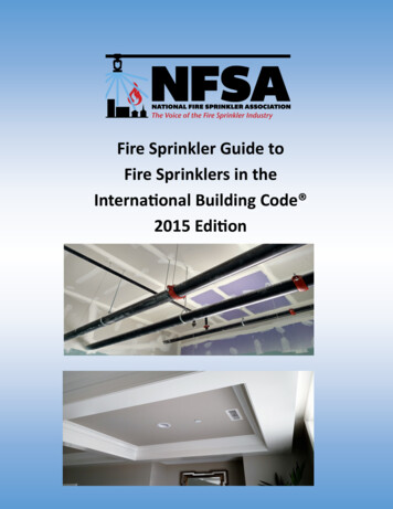
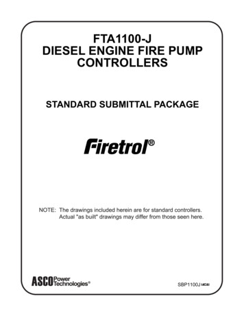
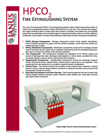
MULTIPLE CYLINDER ARRANGEMENTSDischargePressure Switch(P/N 18773)Discharge ManifoldManual Valve(supplied by installer)Actuator(P/N 19589) Solenoid ValveDischarge Flex Hosew/ Outlet Check Valve(P/N 99706)Assembly(P/N 19585)In multiple cylinder arrangements, eachprimary cylinder is actuated manually orelectrically, and then each slave cylinder isactuated by direct back pressure from thedischarge manifold.For cylinder arrangements composed oftwo cylinders, one primary cylinder is usedwith one slave cylinder. For cylinder arrangements composed of three or morecylinders, NFPA 12 requires two primarycylinders be used.Note: The minimum manifold pressure forslave actuation is 500 psi (34.5 bar).Primary PrimaryCylinder veCylinderTypical Primary and Slave Cylinder ArrangementMAIN/RESERVE CYLINDER ARRANGEMENTSDischargePressure Switch Manual Valve(P/N 18773)Actuator(P/N 19589)Solenoid ValveAssembly(P/N 19585) Vent Check(P/N 10173)Inline Check Valve(sized by JDSsoftware)Vent Check(P/N 10173)Discharge Flex Hosew/ Outlet Check Valve(P/N 99706)MRS-1Main/ReserveTransfer Station(P/N 18846)HPCO2 cylinders may be installedin a main/reserve arrangement. Ina main/reserve system, the number of cylinders required to protecta hazard are installed as the maincylinders. A second set of reservecylinders is installed and connectedto the same discharge piping as themain cylinders. This allows for cylinders to be removed for maintenancewithout taking the HPCO2 systemoffline.Discharge preference is shifted between the main and reserve cylinders using the Janus Fire Systems MRS-1 Main/Reserve Transfer Station (refer to datasheet DS1066).Primary PrimaryCylinder CylinderSlaveCylinderMAIN erRESERVE CYLINDERSTypical Main/Reserve Cylinder ArrangementDS1094Revised: 26-Sep-2018Page 6 of 20Inline check valves are implementedin the discharge manifold to preventthe discharge flow of the main cylinders from actua
The Janus Fire Systems HPCO 2 Fire Extinguishing System utilizes highly pressurized carbon di-oxide as the extinguishing medium. Carbon dioxide (CO 2) is a dry, inert, non-corrosive fire suppres-sion agent perfectly suited to protect high value assets in normally unoccupied and unoccupiable areas when an electrically non-conductive agent is required and where clean-up of other agents is .