Transcription
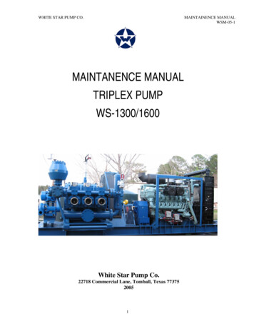
WHITE STAR PUMP CO.MAINTAINENCE MANUALWSM-05-1MAINTANENCE MANUALTRIPLEX PUMPWS-1300/1600White Star Pump Co.22718 Commercial Lane, Tomball, Texas 7737520051
WHITE STAR PUMP CO.MAINTAINENCE MANUALWSM-05-1CONTENTSECTION 1SECTION 2SECTION 3SECTION 4SECTION 5SECTION 6GENERALINSTATLLATIONLUBRICATION SYSTEMINSPECTION AND MAINTEANCEFLUID END REPAIRPOWER END REPAIR2PAGE3511151731-
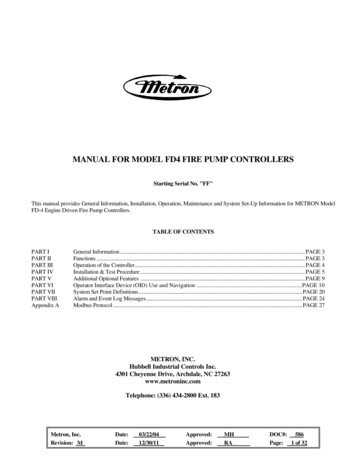
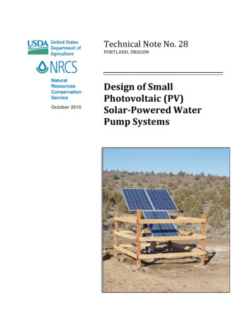
WHITE STAR PUMP CO.MAINTAINENCE MANUALWSM-05-1SECTION 1. GENERALThis section contains the instructions for the installations and startup of the pump at thedrilling site. The instructions presented in this section should be followed for the initialInstallation and startup of the pump, whenever the pump has been moved to a newlocation, or whenever major repairs have been made.Fig 1-1. White Star Triplex Pumpwith One Piece Module3-
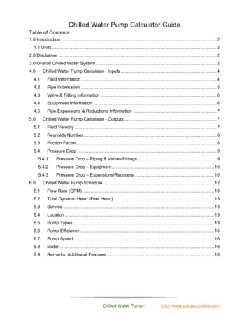
WHITE STAR PUMP CO.MAINTAINENCE MANUALWSM-05-1WARNINGSNEVER REACH INSIDE OPERAING PUMP.NEVER RUN PUMP AGAINST CLOSED VALVES (ALL DISCHARGE VALVES CLOSED).STOP PUMP OPERATION BEFORE ATTEMPTING REPAIRS.PROPERLY LOCK-OUT OR DISCONNECT MAIN POWER SOURCE TO THE PUMP BEFORECONDUCTING INSPECTION, MAINTENANCE OR REPAIR.COMPLETELY BLEED ALL PRESSURE FROM FLUID END BEFORE ATTEMPTING MAINTENANCEOR REPAIR.CAUTIONS A CHARGING PUMP IS ESSENTIAL FOR PROPER OPERATION. FAILURE TO USE ACHARGING PUMP WILL VOID THE PUMP WARRANTY. INSTALL A SUCTION DESURGER TO MINIMIZE MUD CAVITATION.Fig 1-2 Fluid End4-
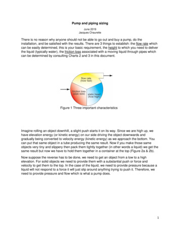
WHITE STAR PUMP CO.Figure 1-1-1MAINTAINENCE MANUALWSM-05-1White Star Triplex Pump with Split ModulesFigure 1-2-1Fluid End with Split Modules5-
WHITE STAR PUMP CO.MAINTAINENCE MANUALWSM-05-1SECTION 2. INSTALLATIONPUMP1. Be sure that the pump foundation is level and able to support the weight of the pump.2. Install the pump as close as possible to the mud tank or pit to reduce drop in suction line.SUCTION SYSTEM1. The diameter of the suction line must be equal to or exceed the diameter of the pump suctionconnection.2. Use as short a suction line as possible.3. Install the suction line in as straight a line possible. If turns are necessary use long radius ells.4. Install a section hose in the suction line to isolate vibration.5. Be sure there are no air traps or air leaks in the suction line.6. Install a charging pump in the suction line. (See CHARGING PUMPS.)7. Install a suction desurger to prevent mud cavitation. (Refer to FLUID END ACCESSORIES inSection 4 of this guide.)8. Fully open all valves in the suction line before operating the pump.DISCHARGE SYSTEMWARNINGTHE DISCHARGE SYSTEM IS SUBJECT TO HIGH PRESSURES.FAILURE TO FOLLOW APPROVED WELDING PROCEDURES ON ANY OF THE DISCHARGE PIPEMANIFOLDING; OR, PIPING BEYOND MANIFOLDING SUBJECTED TO INTERNAL PRESSURESFROM PUMP OPERATION COULD RESULT IN PIPING FAILURE CAUSING EQUIPMENT DAMAGEOR PERSONAL INJURY.1. Install a pressure relief valve in the discharge system. Be sure there are no valves or restrictions,including the strainer assembly, between the pump and the relief valve.6-
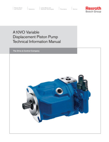
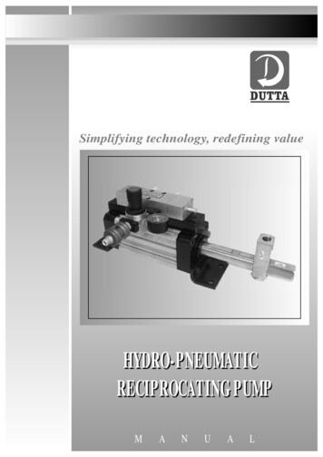
WHITE STAR PUMP CO.MAINTAINENCE MANUALWSM-05-1CAUTION THE PRESSURE SETTING OF THE VALVE MUST NOT EXCEED THE PRESSURE RATING OFTHE LINER SIZE INSTALLED IN THE PUMP.NOTE:The pressure ratings for the liners are listed in the specification charts at the back of this guide. Theyare also indicated on the pump serial number plate.2. Install a pulsation dampener in the discharge system to reduce vibration and increase componentservice life. (Refer to FLUID END ACCESSORIES in section 4 of this guide.)NOTE:The standard WHITE STAR strainer assembly has an API 4” 5000 psi WP RTJ flange for dampenerinstallation.DIRECTION OF THE PUMP ROTATION1. Be sure that the pump is set to rotate in the direction indicated by the arrow in the picture below the(Figure 1–3)2. Do not rotate the pump in the opposite direction of the arrow unless the oil pump suction anddischarge lines have been reversed.3. If it becomes necessary to use the back side of the gear teeth (because of normal wear), turn thepinion and crankshaft assemblies end for end and move the oil pump to the opposite side of thecrankcase.Fig. 1-3 Direction of Rotation7-
WHITE STAR PUMP CO.MAINTAINENCE MANUALWSM-05-1INITIAL OPERATIONTake special care when operating the pump for the first time or after major repairs have been made.Refer to the caution remarks under STARTUP, Page 1-4CAUTION PUMPS ARE SHIPPED FROM THE FACTORY WITHOUT LUBRICANT. BE SURE THE PUMP ISPROPERLY LUBRICATED BEFORE OPERATING.PREPARATION1. If the pump was not completely assembled at the factory, complete the assembly as required.2. Check to be sure the suction and discharge systems have been properly installed. (SEEINSTALLATION)3. Remove the cover plates from the power end.4. Inspect the power end for contamination. Clean as required.5. Drain all condensation from the power frame (Figure 1-4).DRAINPLUGFig. 1-4 Power end drain plugDo not attempt to drain condensation from power frame if unit has been filled with lubricant. (why?)6. Install cover plates.7. Check that crankcase drain plug is installed and tight.8. Fill the power end with correct lubricant.8-
WHITE STAR PUMP CO.MAINTAINENCE MANUALWSM-05-1NOTE:Lubricant specifications and quantities for the pump are listed in LUBRICATION section of this guideand on the pump name plate.9. Check and lubricate grease fittings on piston wash system.10. Make sure all covers are installed and all nuts and bolts are tightened to the torque specificationslisted at the back of the guide.11. Fill piston wash system with water and / or coolant.a. Slide reservoir cover open to fill reservoir.b. Replace cover.NOTE:Add anti-freeze to piston wash system if there is a possibility of freezing.CAUTION IF THERE ARE UNUSUAL NOISES OR OTHER INDICATIONS THAT THE PUMP IS NOTOPERATING CORRECTLY, STOP THE PUMP IMMEDIATELY AND CORRECT THE PROBLEMBEFORE CONTINUING OPERATION. IF OIL PRESSURE EXCEEDS 40 PSI OR FALLS BELOW 5 PSI STOP THE PUMP IMMEDIATELYAND CORRECT THE PROBLEM BEFORE CONTINUING.1. Operate pump slowly, 50 strokes per minute maximum, for 5 minutes with no fluid end pressure.2. Be sure that the oil pressure gauge indicates between 5 and 40 psi (Figure 1-5)Fig. 1-5 Oil pressure gauge9-
WHITE STAR PUMP CO.MAINTAINENCE MANUALWSM-05-13. Check each liner to ensure that the position wash system is operating properly.4. After 5 minutes of slow speed operation, stop the pump. Allow 10 minutes for oil to return to thecrankcase and check the lubricant level. If required, add oil until the level reaches the FULL markon the dipstick. (Refer to the LUBRICATION section of the guide.)5. Restart the pump. With no pressure on the fluid end, gradually increase the speed until the normaloperating speed is reached.CAUTION IF THERE ARE UNUSUAL NOISES OR OTHER INDICATIONS THAT THE PUMP IS NOTOPERATING CORRECTLY, STOP THE PUMP IMMEDIATELY AND CORRECT THE PROBLEMBEFORE CONTINUING.IF OIL PRESSURE EXCEEDS 40 PSI OR FALLS BELOW 5 PSI STOP THE PUMPIMMEDIATELY AND CORRECT THE PROBLEM BEFORE CONTINUING.6. Be sure the oil pressure gauge indicates between 5 and 40 psi.7. Check each liner to ensure that the piston wash system is operating properly.8. Gradually increase fluid end pressure until the desired pressure is reached.WARNINGDO NOT EXCEED THE MAXIMUM OPERATING PRESSURE INDICATED ON THE PUMP NAMEPLATE AND LISTED IN THE SPECIFIACTION CHARTS IN THIS GUIDE.DO NOT ATTEMPT TO PUMP AGAINST CLOSED DISCHARGE VALVES.9. Operate pump for 30 minutes at required operating pressure. As pump operates inspect around thenuts of the liners, the cylinders and the valves for leaks. If leaks are found, stop the pumpimmediately, make the necessary repairs and restart the pump.10. Stop the pump after 30 minutes of operation.11. Inspect all studs, nuts and cap screws. Tighten if necessary. Torque specifications are listed at theback of this guide.12. The pump is now ready for normal operation.CHARGING PUMPSCAUTION FAILURE TO USE A CHARGING PUMP WILL VOID PUMP WARRANTY.10-
WHITE STAR PUMP CO.MAINTAINENCE MANUALWSM-05-1The charging pump provides back pressure to the suction and prevents mud cavitations. This isessential to the flow and life of the fluid end.Existing mud circulation pumps can be piped into the suction line if they are capable of delivering themaximum rated flow rate of the triplex pump while maintaining a pressure of 40 psi. Refer to theperformance charts.NOTE:Maintain proper belt tension on charging system pump.SECTION 3 LUBRICATION SYSTEMWARNINGSNEVER REACH INSIDE OPERATING PUMP.NEVER RUN PUMP AGAINST CLOSED VALVES (ALLL DISCHARGE VALVES CLOSED).STOP PUMP OPERATION BEFORE ATTEMPTING REPAIRS.PROPERLY LOCK-OUT OR DISCONNECT MAIN POWER SOURCE TO THE PUMP BEFORECONDUCTING INSPECTION, MAINTENANCE OR REPAIR.COMPLETELY BLEED ALL PRESSURE FROM FLUID END BEFORE ATTEMPTING MAINTENANCEOR REPAIR.CAUTIONS PUMPS ARE SHIPPED FROM THE FACTORY WITHOUT LUBRICANT. BE SURE PUMP ISPROPERLY LUBRICATED BEFORE OPERATING. IF OIL PRESSURE EXCEEDS 40 PSI OR FALLS BELOW 5 PSI STOP THE PUMP IMMEDIATELYAND CORRECT THE PROBLEM BEFORE CONTINUING OPERATION.SYSTEM DESCRIPTIONWhite Star Triplex pumps have two independent lubrication systems which provide lubricating oil to allmoving parts of the pump. In addition to a pressure-fed primary system, each pump has a gravity –fedsecondary system that is supplied by splash from the main gear.Model WS1600 may have an external lubrication pump driven by motor on request.11-
WHITE STAR PUMP CO.MAINTAINENCE MANUALWSM-05-1Normal oil pressure for the primary lubrication system, as indicated by the pressure gauge, is 5 to 40 psidepending upon the temperature of the oil and the operating speed of the pump.PRIMARY SYSTEMOil in the crank case sump enters the strainer and supplies the pump through the suction line. The oil isthen pumped to the gearcase manifold which contains the pressure gauge connection, a relief valve (setto open at 40 psi), and outlets to main bearings, pinion bearings and crosshead manifold.Fig. 2-1 Oil pump locationOil pumped to the crosshead manifold is directed to each crosshead guide and onto each crosshead viagrooves. The oil lubricates the upper crosshead guides and crosshead and then flows into theconnecting rods, through holes in the rods and into the wrist pin bearings. The oil flows out of the wristpin bearings through hole in the bottom of the crossheads and onto the lower crosshead guides.Oil from the crosshead manifold also feeds an oil cup on each wrist pin retainer plate. This oil passesthrough a hole in each wrist pin to the inner race of the wrist pin bearings and then onto the lowercrosshead guides ensuring adequate lubrication of the bearings.The crosshead manifold also supplies a stream of oil to each extension rod as the rods pass throughthe stripper boxes.SECONDARY SYSTEMEach part lubricated by the primary system also receives oil from the gravity-fed secondary lubricatingsystem. Two reservoirs, one above the crosshead compartment and one behind the pinion (Figure 2-2)are supplied with oil by splash from the main gear.10-
WHITE STAR PUMP CO.MAINTAINENCE MANUALWSM-05-1RESERVOIRFig. 2-2 Secondary lubricating system.LUBRICANT LEVEL1. Check the lubricant level of the pump at regular intervals. The dipstick is located at the rear of thepower frame (Fig 2-3).OIL LEVELDIPSTICKFig. 2-3. DipstickNOTE:Every pump is equipped with two dipsticks (one on each side of the power frame) for convenience.11-
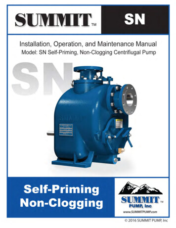
WHITE STAR PUMP CO.MAINTAINENCE MANUALWSM-05-12. If the Pump is operating, the lubricant level should be at the run mark on the dipstick.NOTE:If the lubricant level does not reach the RUN mark on the dipstick when checked, stop the pump.3. If the pump has been stopped for at least 10 minutes, the lubricant level should be between theADD and FULL marks on the dipstick.4. Add lubricant if necessary.RECOMMENDED LUBRICANTSNOTE:The recommended lubricants for the White Star mud pumps are shown in Fig. 2-6. Consult your WhiteStar service representative before using lubricants other than those listedLUBRICANT CHANGES1. Drain the old lubricant every 4 months or 1000 operating hours, whichever occurs first. The drainplug is located at the rear of the power frame (Figure 1-4).2. Fill the pump with fresh lubricant. (Fig. 2-6)CAUTIONCHANGE LUBRICANT IF CONTAMINATED BY DIRT,CONDENSATION OR OTHER FOREIGN SUBSTANCES.12DRILLINGFLUID,EXCESSIVE-
WHITE STAR PUMP CO.MAINTAINENCE MANUALWSM-05-1AMBIENT TEMPERATUREBRAND OF LUBRICANT- 20 Deg F to 15 Deg F 15 Deg. F to 125 Deg FAGMA NO.No. 1 EPNo. 4 EPGULF-EP Lubricant 75EXXONPen-O-Led EP 1Pen-O-LedSHELL-Spirax HD 90MOBILComp AAMobilgear 626Comp. BBMobilgear 629TEXXACOMeropa Lubricant 1Multigear Lubricant EP 80Meropa Lubricant 2NOTE: The Capacity of Oil for White Star WS-1300/1600 is 120 gal.Fig. 2-6. Recommended lubricants13-
WHITE STAR PUMP CO.SECTION 4MAINTAINENCE MANUALWSM-05-1INSPECTION AND MAINTENANCEWARNINGSNEVER REACH INSIDE OPERATING PUMP.NEVER RUN THE PUMP AGAINST CLOSED VALVES (ALLL DISCHARGE VALVES CLOSED).STOP PUMP OPERATION BEFORE ATTEMPTING REPAIRS.PROPERLY LOCK-OUT OR DISCONNECT MAIN POWER SOURCE TO THE PUMP BEFORECONDUCTING INSPECTION, MAINTENANCE OR REPAIR.COMPLETELY BLEED ALL PRESSURE FROM FLUID END BEFORE ATTEMPTING MAINTENANCEOR REPAIR.PREVENTIVE MAINTENANCEThe primary goal of a preventive maintenance program is to help the pump owner realize and controlfluid circulating equipment operating costs. It is possible to control mud pump cost if life of fluid endparts can be reasonably predicted so that they can be replaced before they fail. Parts that are run to thepoint of failure result in unscheduled downtime, damage to other parts and excessive man hours beingspent for pump repair.Besides following a program of scheduled inspection and maintenance, the owner should develop aplan for the timely replacement of expendable components based upon the average life expectancy ofthese components.By changing expendable parts in a group on a timely basis you can eliminate the need to continually gointo the pump for routine maintenance. Changing parts or performing other schedule inspections whileyou are shut down for some other event that does not require pump operation (making cement, logging,etc.) further reduces pump down time.SCHEDULE MAINTENANCEDAILY (8 HOURS)1.2.3.4.CHECK CRANKCASE OIL LEVEL.CHECK OIL PRESSURE.CHECK OIL FOR CONTAMINATION.CHECK STRIPPER BOX PACKING.14-
WHITE STAR PUMP CO.5.6.7.8.9.10.11.12.13.MAINTAINENCE MANUALWSM-05-1LUBRICATE CHARGING PUMP.CHECK DISCHARGE PRESSURE.CHECK FOR OIL LEAKS.CHECK FOR FLUID LEAKS.CHECK SUCTION DESURGER FOR PROPER PRESSURE.CHECK DISCHARRGE PULSATION DAMPENER FOR PROPER PRESSURE.CHECK PISTON LUBRICATION SYSTEM.CHECK PUMP FOR CLEANLINESS.CHECK WORK AREA FOR CLEANLINESS.WEEKLY (40 HOURS).1. CHECK ALL SAFETY CONTROLS.2. CHECK PISTON ROD CLAMPS.3. PERFORM ALL DAILY CHECKS.MONTHLY (200 HOURS).1.2.3.4.5.6.7.8.9.CHECK ALLL FLUID END AND POWER END BOLTS FOR PROPER TIGHTNESS.CHECK LINER AND PISTON WEAR.CHECK EXTENSION ROD FOR WEAR.CHANGE PISTON WASH SYSTEM WATER.CLEAN CRANKCASE BREATHERS.CLEAN OIL FILTER (S).CHECK VALVE SEATS AND VALVE SPRINGS.CHECK AVAILABILITY AND CONDITION OF SPECIIAL TOOLS.PERFORM ALL DAILY AND WEEKLY CHECKS.SIX MONTHS (1000 HOURS)1.2.3.4.5.6.7.8.CHECK CROSSHEAD CLEARANCE (SEE SPECIFICATIONS).CHECK FOUNDATIONS AND/ OR HOLD ON BOLTS.CHECK GEARS AND / OR CHAIN AND SPROCKETS FOR WEAR.CHECK SUCTION FLANGE BOLTING.CHECK DISCHARGE FLANGE BOLTING.CHECK PUMP SHEAVE, SPROCKET OR COUPLING.CHANGE OIL.PERFORM DAILY, WEEKLY AND MONTHLY CHECKS.15-
WHITE STAR PUMP CO.MAINTAINENCE MANUALWSM-05-1SECTION 5.FLUID END REPAIREXPENDABLESGaskets, valves, valve seats, valve springs, liners and pistons are considered expendable components.A liner davit (Figure. 4-1) is available to aid in handling heavy components.Figure 4-1 Liner davitWARNINGSNEVER REACH INSIDE OPERATING PUMP.NEVER RUN PUMP AGAINST CLOSED VALVES (ALL DISCHARGE VALVES CLOSED).STOP PUMP OPERATION BEFORE ATTEMPTING REPAIRS.PROPERLY LOCK-OUT OR DISCONNECT MAIN POWER SOURCE TO THE PUMP BEFORECONDUCTING INSPECTION, MAINTENANCE OR REPAIR.COMPLETELY BLEED ALL PRESSURE FROM FLUID END BEFORE ATTEMPTING MAINTENANCEOR REPAIR.Be sure to tighten fasteners to the proper torque value. Torque specifications for important fluid endfasteners are given at the back of this guide. Refer to standard SAE torque chart for any fasteners notlisted in this guide.16-
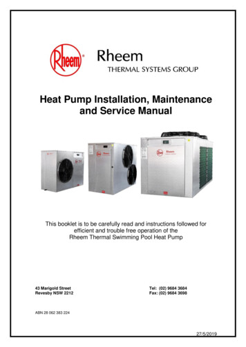
WHITE STAR PUMP CO.MAINTAINENCE MANUALWSM-05-1GASKET REPLACEMENT1. Use a hammer and steel bar to remove threaded cylinder head or discharge valve cover plugretainer. (Fig. 4-2)CYLINDER HEADPLUG RETAINERFigure 4-2 Removing cylinder head plug retainer2. Remove cylinder head or discharge valve cover plug and gasket. (Fig 4-3)Figure 4-3 Cylinder head plug and gasket3. Inspect gasket. Discard if damage or worn.4. Clean gasket groove and lubricate with multipurpose grease. (Fig. 4-4)17-
WHITE STAR PUMP CO.MAINTAINENCE MANUALWSM-05-1Figure 4-4 Gasket groove5. Install gasket. Use new gasket if necessary.6. Install cover plug and retainer. Tighten retainer with hammer and steel bar.NOTE:Threaded retainers are buttress fit and must be tighten completely.SUCTION VALVESREMOVAL1. Remove cylinder head plug retainer (Figures 4-2)2. Remove cylinder head plug and inspect gasket (Figure 4-3). Remove and discard gasket ifdamaged or worn.3. Pull wedge shaped valve retainer from slot in suction valve guide (Figures 4-5)Fig. 4-5 Removing suction valve retainer18-
WHITE STAR PUMP CO.MAINTAINENCE MANUALWSM-05-14. Rock valve guide slightly to loosen. Lift guide upward in vertical bore and rotate 90 degrees toremove (Figures 4-5, 4-6).Figure 4-6 Removing suction valve guide5. Remove suction valve and valve spring (Figures 4-7)Fig. 4-7 Removing suction valve and valve springINSTALLATION1. Position valve on valve seat.2. Place valve spring over valve.3. Insert valve guide lengthwise (with one of the curved surfaces facing the piston) until the center ofthe guide is over the valve stem and spring (Figure 4-8)19-
WHITE STAR PUMP CO.MAINTAINENCE MANUALWSM-05-1Figure 4-8 Installing suction valve guide4. Rotate the guide 90 degrees, mating the curved surfaces to the guide with the curved surfaces ofthe vertical bore.5. Push the guide down over the valve stem and spring.6. Push valve guide down and install wedge- shaped retainer in slot valve guide. (Figure 4-9)Figure 4-9 Installing suction valve retainerNOTE:Make sure valve guide retainer is all the way in.CAUTION VALVE GUIDE WILL BE DAMAGED DURING PUMP OPERATION IF COCKED ORMISALINGNED DURING INSTALLATION.7. Inspect the valve guide and retainer to be sure they are installed correctly. (Fig. 4-5)8. Install cylinder head gasket.9. Use pipe dope or grease for threads and install cylinder head plug and retainer.20-
WHITE STAR PUMP CO.MAINTAINENCE MANUALWSM-05-110. Tighten cylinder head plug retainer with hammer and steel bar.NOTE:Cylinder head plug retainer is buttress fit and must be tighten completely.DISCHARGE VALVESREMOVAL1. Remove the threaded cover plug retainer with hammer and steel bar.2. Remove the cover plug with valve guide (Figure 4-10).Figure 4-10 Cover plug with valve guideNOTE:The discharge valve guide for White Star-1600 is bolted to the cover plug. (Figure 4-10).3. Remove discharge valve and valve spring.INSTALLATION1. Position discharge valve on the valve seat.2. Place valve spring over valve.3. Inspect cover plug gasket. Replace if damaged or worn.21-
WHITE STAR PUMP CO.MAINTAINENCE MANUALWSM-05-14. Install cover plug making sure that the valve guide is correctly positioned over valve.5. Install threaded cover plug retainer. Tighten with hammer and steel bar. (Figure 4-11).Figure 4-11 Tightening thread retainerNOTE:Threaded cover plug retainer is buttress fit and must be tightened completely.VALVE SEATSREMOVALCAUTION NEVER USE A TORCH TO REMOVE VALVE SEATS. EXCESSIVE HEAT WILL DISTORTFORGINGS AROUND VALVES SEATS.1. Remove valve guide and valve (see section on appropriate valve).
Gradually increase fluid end pressure until the desired pressure is reached. WARNING DO NOT EXCEED THE MAXIMUM OPERATING PRESSURE INDICATED ON THE PUMP NAME PLATE AND LISTED IN THE SPECIFIACTION CHARTS IN THIS GUIDE. DO NOT ATTEMPT TO PUMP AGAINST CLOSED DISCHARGE VALVES. 9. Op