Transcription
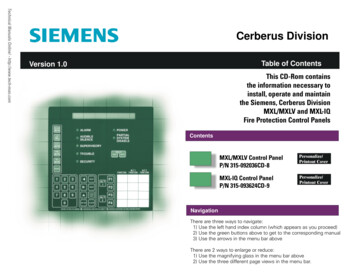
MANUAL FOR MODEL FD4 FIRE PUMP CONTROLLERSStarting Serial No. "FF"This manual provides General Information, Installation, Operation, Maintenance and System Set-Up Information for METRON ModelFD-4 Engine Driven Fire Pump Controllers.TABLE OF CONTENTSPART IPART IIPART IIIPART IVPART VPART VIPART VIIPART VIIIAppendix AGeneral Information . PAGE 3Functions . PAGE 3Operation of the Controller . PAGE 4Installation & Test Procedure . PAGE 5Additional Optional Features . PAGE 9Operator Interface Device (OID) Use and Navigation .PAGE 10System Set Point Definitions . PAGE 20Alarm and Event Log Messages. PAGE 24Modbus Protocol . PAGE 27METRON, INC.Hubbell Industrial Controls Inc.4301 Cheyenne Drive, Archdale, NC 27263www.metroninc.comTelephone: (336) 434-2800 Ext. 183Metron, Inc.Revision: OC#: 586Page: 1 of 32
THIS PAGE IS BLANKPage 2 of 32File Name: Doc#586m.doc
PART I: GENERAL INFORMATIONThe basic function of the model FD4 Fire Pump Controller for diesel engine driven fire pumps is to automatically start the engineupon a drop in pressure in the water main, or from a number of other demand signals. This controller provides automatic cycledcranking, alarm and/or alarm shutdown protection for various engine failures. Stopping of the engine after the demand period is overmay be either manual or automatic. This controller also includes an automatic weekly test starting feature.PART II: FUNCTIONSEquipment is provided in the Controller to provide the following functions:A. Automatic Starting From:a. Drop in water line pressureb. Loss of battery charger output (if enabled)c. Operation of optional remote start switches, such as remote start switch, deluge valve switch, fire alarm switch, etc.d. Weekly test timerB. OID – Operator Interface Device - Provided for display of alarm functions, system pressure, battery volts, battery charger amps,alarm conditions, etc. Includes a 4 line by 20 character LCD for display of system messages and programming.C. Auto-Off-Manual selector switch.D. Automatic Cranking - A microprocessor controlled crank cycle timer provides six (6) fixed crank periods separated by five (5)rest periods each of approximately 15 seconds duration.E. Alarms and Signal Lights - Fourteen (14) Standard lights are provided to give visual signals for; "System Fault”, "Battery #1Healthy”, Battery #2 Healthy", "Charger #1 Failure", Charger #2 Failure”, “AC Power Loss”, “Engine Running”,"Engine Failed to Start", "Engine Low Oil Pressure", "Engine High Water Temp", "Engine Overspeed", “Low Fuel”,“Pump On Demand”, ”Contactor Coil Failure”, ”ECM Alternate”,and ”ECM Failure”. In addition the mode buttonshave LED’s on the button indicating “Auto”, Manual”, “Test”, or “Off” mode. 8 additional lights, configurable by thefactory, can be provided for "Pump Room Alarms". An audible alarm horn is mounted on the front of the cubicle forsounding in the event of failure. Terminals are provided for remote failure indication of the following:"Automatic Mode""System Fault""Engine Running (2 sets)""Common Battery Fault"F.A data logger is provided as standard to record system pressure along with numerous alarm conditions and system events. Thedata can be displayed on the OID or can be downloaded to a PC through the RS485 port provided on the main system board.Data is stored on an SD Memory card. This card contains individual pressure files with each file containing one days worth ofpressure data. Each file is of the PressXXX.txt format. Each entry is stamped with the date and time and system pressure at thattime. The Events.txt file contains all of the logged events with each event stamped with date and time. The SD memory card canbe removed and files transferred directly to a PC using appropriate memory card reader. The controller will continue to operatenormally with the SD card removed. There will, however, be a visual and audible alarm when the card is removed. Events andpressure data will continue to be logged while the card is missing. The memory cards should be replaced within 12 hours toensure that no data is lost.G. A weekly test timer is supplied to automatically start the engine any set day of the week, at a set time of day, and a preset runtime. See Part IV below for more information and the System Config Screen 106.H. "Stop" Pushbutton - A pushbutton is provided to stop the engine in Auto at any time provided all starting demands havecleared. This returns the controller to the automatic position. The Auto-Off-Manual selector switch can also be put in the “Off”mode to stop the engine. Any starting commands will not start the engine in the “Off” mode.I.Integral Battery Chargers (Option J). There are two separate fully automatic, solid state chargers provided for maintaining fullcharge on the dual sets of engine batteries. An LED display is provided on each charger to indicate charger AC input voltage ispresent and DC output voltage is present.User Preferences Screen 218 and 219 are used to determine when the Charger Failure alarm will activate. When Screen 218 isset to No, the Charger Failure alarm will not be active while the engine is running. Should both chargers fail or switch off due toa high voltage output from the engine alternator, the AC Power Failure lamp may come on. This is normal. It will resetPage 3 of 32File Name: Doc#586m.doc
automatically once the engine stops running and the charger failure alarms reset. When Screen 218 is set to Yes, the ChargerFailure alarm will be active at all times when the Mode selector switch is in the Auto or Manual mode. Screen 219 is used todetermine the time delay between the failure contacts on the charger closing and the Charger Failure lamp and audible alarmsounding on the controller.J.Cabinet - A heavy gauge steel cubicle encloses the controller. The OID, the key operated Auto-Off-Manual (AOM) SelectorSwitch and manual start pushbuttons are mounted on the outer door. The battery circuit breakers are located inside the cabinet onthe main back panel of the unit. A key for the AOM switch is stored in a break-glass housing on the door of the cabinet. Anadditional key is located inside the cabinet.PART III: OPERATION OF THE CONTROLLERA. When the controller is the "Auto" mode and both circuit breakers are in the "On" position, the controller is in standbycondition ready to start the engine automatically. A green pilot light above the "Auto" button will illuminate in this mode.Also, Battery #1 Fault and Battery #2 Fault lights should be off indicating that battery power is available.When the water pressure drops below a level which is set in System Config Screen 101, the Controller will actuate the startermotor and the cranking cycle will commence. In addition the “Pump on Demand” light will illuminate. If the engine starts andruns, cranking will cease and the protective circuits will be operative. If the engine fails to start after six (6) crank periods,cranking will cease, the "Engine Failed to Start" light will illuminate, and the alarm horn will sound. The fuel solenoid willstay on for one hour however. This is to allow the engine to continue to run in the event the failed to start condition was due to afaulty speed switch signal from the engine. The battery alternating circuit alternates batteries on each crank attempt unless onebattery is in a discharged state and incapable of cranking the engine. In this instance, the control will lock onto the other batteryfor the remaining cranking attempts. Dry contacts for remote indication of "Battery Failure" are provided.The panel is wired so that optional remote start switches may be used, such as Deluge Valve, Remote Start pushbutton, ExternalPressure , These start switches will also cause the “Pump on Demand” light to illuminate.etc. In addition, when “PowerFailure Engine Startup” feature is enabled (System Config Screen 111), the Controller will automatically start the engine uponloss of Battery Charger output or AC Power loss, after an adjustable time delay (System Config Screen 112).While the engine is running, all protective circuits are operative. If the engine stops while running, and there is still an auto startdemand, the control will attempt to restart the engine. If the engine fails to start the "Engine Failed to Start" light willilluminate and the alarm will sound. If, while the engine is operating, the oil pressure drops below a safe limit, the “Low OilPressure” light will illuminate immediately. After approximately seven (7) seconds the alarm will sound. Should the enginetemperature exceed a safe limit while running, the “Engine High Water Temp.” light will illuminate after a seven (7) secondtime delay and the alarm will sound indicating engine overheating.In case of Overspeed, the engine will be stopped and the "Engine Overspeed" light will illuminate and the alarm will sound.The light and alarm will stay on until the Engine Speed Switch and the Controller are manually reset. To manually reset theController, turn the controller selector switch to Off, then press the Reset button. Then turn the selector switch back to “Auto”.The Controller may be configured as either "Manual" or "Automatic" stop as required (System Config Screen 104)."Manual" stop is set as standard. The current status of this setting is visible on the Main System Status Screen where the letter“A” will appear in the upper right hand corner of the screen when set to Automatic Stop and an “M” will appear when set forManual stop. When Automatic stop is enabled the stop timer is preset at the factory to 30 minutes. Longer time settings can beset in System Config screen 105 with a maximum setting of 60 minutes possible. When “Automatic Stop” is disabled, theengine will continue to run even though the pressure switch or other remote starting switch returns to its normal position. Theengine can be stopped immediately only by pressing the stop button or by turning the Auto-Off-Manual switch to the Offposition. On engines that do not use the “energize to stop” method (i.e. Caterpillar), the engine may also be stopped by turningthe circuit breakers BATT1 and BATT2 to OFF. If set up for "Automatic" stop, the engine will be stopped automatically uponrestoration to normal of whatever demand switch started the engine providing it has run at least 30 minutes or longer as set inSystem Config screen 105. If the demand period was less than the time set on the auto stop timer, the engine will continue torun until the timer times out and then will stop.B. When the "Test" mode button is pressed for two or more seconds, the engine will be started by causing a drop in waterpressure. Failure alarm circuits will be operative in the "Test" mode. This method of starting provides a test of the Controller,thereby assuring proper operation when required. The engine will run for the time set in Auto Weekly Test Length Of Run Time(System Config Screen 109) or until the "Stop" push button is pressed or the selector switch is turned to “OFF”.C. The "Manual" position of the Auto-Off-Manual switch is for manually starting the engine from either battery. The fuel andwater solenoids are energized in this position, and the engine must be cranked by pushing one of the buttons located below thePage 4 of 32File Name: Doc#586m.doc
OID. "Manual Crank 1" cranks from Battery 1, and "Manual Crank 2" cranks from Battery 2. Pressing both buttons willresult in cranking from both batteries simultaneously.D. When the engine is given a command to stop for any reason, terminal 12 will energize and will remain on for approximately 15seconds. The controller will not start until terminal 12 is de-energized again.E. Periodic Self Testing - The Test Run Timer can be set to give test runs on any day of the week and time of day desired. Atiming element is incorporated in the control so that when the engine starts in this manner, it will run for a definite time before itshuts down. See System Config Screens 106 through 109 to set the starting time and length of engine running.F.Provision for sequential starting is accomplished by the use of adjustable time delay on pressure drop starting or “Deluge Valve”starting. On Multiple Pump installations these timers are set sequentially and progressively longer in time to prevent more thanone (1) pump from starting simultaneously with another pump. Failure of the lead pump to start will not prevent subsequentpumps from starting. The time delay on starting is set in System Config Screen 103.G. The “Pump On Demand” alarm light is provided to indicate that there is a command to start and run the additive pumpcontroller. This includes a low pressure condition, deluge valve start signal etc. The alarm light will clear when the startcondition has been cleared such as the water pressure in the system rises above the high set point set in screen 102.H. The “Contactor
The basic function of the model FD4 Fire Pump Controller for dies el engine driven fire pumps is to automatically start the engi ne upon a drop in pressure in the water main, or from a number of other demand signals. This controller provides automatic cycled cranking, alarm and/or alarm shutdown protection for various engine failures. Stopping of the engine after the demand period is over
