Transcription
Installation, Operation and Maintenance ManualiiSUMMIT PUMP MODEL SN
Installation, Operation and Maintenance ManualWARRANTYPumping units assembled by Summit Pump, Inc., Green Bay, WI are guaranteed to befree from defects in material and workmanship for one year from date of shipment fromfactory in Green Bay, WI. The obligation under this Warranty, statutory or otherwise, islimited to replacement or repair at Green Bay, WI, of such part as shall appear to us uponinspection at such point, to have been defective in material or workmanship.This Warranty does not obligate Summit Pump, Inc. to bear the cost of labor ortransportation charges in connection with replacement or repair of defective parts; norshall it apply to a pump upon which repairs or alterations have been made unlessauthorized by Summit Pump, Inc.No warranty is made in respect to engines, motors, or trade accessories, such beingsubject to warranties of their respective manufacturers.No express implied or statutory warranty, other than herein set forth is made orauthorized to be made by Summit Pump, Inc.In no event shall Summit Pump, Inc. be liable for consequential damages or contingentliabilities arising out of the failure of any Summit Pump, Inc. pump or parts thereof tooperate properly.SUMMIT PUMP, INC. Green Bay, WILIABILITYSummit Pump, Inc. shall not be liable for personal physical injury, damage or delayscaused by failure to follow the instructions and procedures for installation, operation andmaintenance contained in this manual.The equipment is not for use in or with any nuclear facility or fire sprinkler system.Buyer accepts the responsibility for insuring that the equipment is not used in violationand Buyer shall indemnify and hold Seller harmless from any and all liability (includingsuch liability resulting from seller’s negligence) arising out of said improper use.COPYRIGHTThis Installation, Operation, and Maintenance Manual contains proprietary information,which is protected by copyright. No part of this Installation, Operation, and MaintenanceManual may be photocopied or reproduced without prior written consent from SummitPump, Inc.The information contained herein is for informational use only and is subject to changewithout notice. Summit Pump assumes no responsibility or liability for any errors orinaccuracies that may appear in this manual. 2016 by Summit Pump. All rights reservedSUMMIT PUMP MODEL SNiii
Installation, Operation and Maintenance ManualivSUMMIT PUMP MODEL SN
Installation, Operation and Maintenance ManualSUMMIT PUMP MODEL SNv
Installation, Operation and Maintenance NTENTSVI2INTRODUCTION22.1 SAFETY3433.1 LIFTING3.2 RECEIVING THE PUMP3.3 STORING THE PUMP3344.14.24.34.44.555557ASSEMBLY PROCEDURES10vi88991011IMPELLER CLEARANCE1111126.1 PROCEDURE TO SET 7.85LOCATIONFOUNDATIONPIPINGBYPASS LINEAUTOMATIC AIR RELEASEVALVE (AARV)4.6 ALIGNMENT4.7 DIRECT COUPLED PUMP4.8 BELT DRIVEN PUMP5.1 ROTATING ASSEMBLY5.2 FRONT COVER AND WEARPLATE ASSEMBLY5.2.1 SN03A, SN04A, SN06A,SN08A 1162RECEIPT AND STORAGEINSTALLATION5.2.2 SN10A SUCTION HEADASSEMBLY5.3 INSTALLING ROTATINGASSEMBLYIII8PRIMINGSTARTINGLINES WITH A BYPASSLINES WITHOUT A BYPASSLIQUID TEMPERATUREBACK FLUSHINGSHUTDOWNBEARING TEMPERATURELUBRICATION8.1 MAINTENANCE SCHEDULE8.2 SEAL ASSEMBLY8.3 BEARINGS9DISASSSEMBLY PROCEDURES131314141415161617181818181910 APPENDIX A – PUMP CROSSSECTION AND PARTS LIST2111 APPENDIX B – CARTRIDGEMECHANICAL SEAL CROSS SECTION2212 PUMP INFORMATION24SUMMIT PUMP MODEL SN
Installation, Operation and Maintenance ManualSUMMIT PUMP MODEL SN
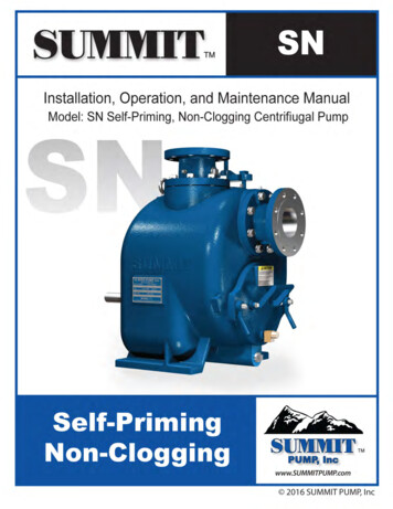
Installation, Operation and Maintenance Manual2INTRODUCTIONThis pump is a centrifugal, self-priming, non-clogging pump with a semi open impeller.It is designed to pump liquids, i.e. water, mild corrosive slurries including solids up to 3”diameter.It is imperative to your safety, and the safety of others, that the pump be used only inapplications for which it has been designed. If you have any questions regarding aspecific application, call Summit Pump, Inc at (920) 869-4800. It is equally as importantthat the pump is operated according to this manual and all personnel in contact with thispump fully understand it.For information or technical assistance on the power source, contact the power sourcemanufacturer’s local dealer or representative.2.1SAFETYThe following messages are used throughout this manual to alert maintenance andoperating personnel to procedures that require special attention for the protection andsafety of both personnel and equipment. Imminently hazardous situation which, if notavoided, will result in death or seriousinjury. Potentially hazardous situation which, if notavoided, could result in death or seriousinjury. Potentially hazardous situation which, if notavoided, may result in minor or moderateinjury. Includes Information on operation,maintenance, rules or directions. Mayindicate possible property damage.2SUMMIT PUMP MODEL SN
Installation, Operation and Maintenance Manual33.1RECEIPT AND STORAGELIFTING Inspect all lifting equipment and riggingbefore lifting pump. Rig the pump securelyensuring a proper safety factor. Refer toTable 3-1 for pump weightsTable 3-1Pump Size2"3"4"6"8"10"3.2ApproximateWeight in Lbs29243266493417101750RECEIVING THE PUMPImmediately upon arrival, carefully inspect the pump for evidence of damage duringtransit. Locate, read and understand the following tags:SUMMIT PUMP MODEL SN
Installation, Operation and Maintenance ManualImmediately report any damage or missing tags to your Summit Distributor.3.3STORING THE PUMPStore the pump in a clean dry place. Do not remove piping connection covers. If thepump has been used prior to storage, be sure to drain the casing. Rotate the pump shaft at least once perweek to avoid damage to bearings andshaft.Rotate the pump shaft at least once per week to maintain a protective film of oil onbearings and seals. Gaskets can dry out and become brittle over time. Check all jointswith gaskets before putting pump in service. If you anticipate long-term storage, specialtreatment is available for purchase from Summit Pump, Inc.4SUMMIT PUMP MODEL SN
Installation, Operation and Maintenance Manual4INSTALLATION Do not operate without proper guards andother safety devices in place.4.1 LOCATIONLocate the pump as close to the liquid supply as practical. This pump is designed tooperate with a negative suction supply, but also has the ability to operate with a positivesuction supply. The suction pressure must never exceed 50% of the maximum pressurepublished on the pump curve. Suction pressure must never exceed 50%of the maximum pressure published on thepump curve.Locate the pump for accessibility. The pump requires clearance in front of the backcover to permit removal of the cover and easy access to the pump for cleaning andservice. See Appendix A – Pump Drawings.4.2 FOUNDATIONUse a foundation that is sufficient to support pump and driver. It is recommended thatthe foundation mass be five times the equipment mass.4.3 PIPINGPipe or hose can be utilized for suction and discharge lines. Line material must becompatible with the liquid being pumped and able withstand the maximum pressure inthe system plus a conservative safety factor. If hose is used on the suction side it must berigid wall, reinforced type to prevent collapse when pump is operating.All piping must be independently supported and accurately aligned to the pump flanges.Never use force to align piping to the pump flanges. Never use force to align piping to the pumpflangesWhenever practical, run the system piping from the pump.SUMMIT PUMP MODEL SN
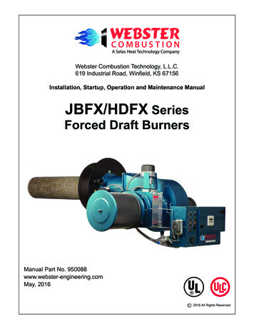
Installation, Operation and Maintenance ManualTable 4-1Pump Size2346810Max Solid1.5”2.5"3"Piping should be as short and straight as possible, while minimizing fittings whichincrease friction losses. Suction line size must be the same size of the pump suctionflange. If a reducer is used, it should be the eccentric type, and installed with the flatportion on top. The suction line should slope up to the suction flange to help reduce airpockets.Piping placed in a sump should be positioned away from any wall by a distance of at least1.5 times the diameter of the suction line. The submergence of the end of the suction lineis vital to efficient pump operation. Recommended submergence is shown in Figure 4-1.Minimum Suction Line SubmergenceMin Submergence in Feet181614121086420024681012141618Velocity in Feet per SecondFigure 4-1Velocity in feet per second Flow rate in GPM X .4085(Diameter in inches)2The discharge line should include a valve that can be used to throttle flow and shutoff.The size of this valve should be equal to the size of the largest discharge line. A checkvalve in the system should be installed to prevent excessive shock pressure and reverserotation flow which could cause pump damage6SUMMIT PUMP MODEL SN
Installation, Operation and Maintenance Manual A valve should never be used to throttle thesuction line4.4BYPASS LINE Do not operate pump with a closed valveother than the AARV (Automatic AirRelease Valve) in the bypass line. Doing somay result in an unsuccessful prime andpossible explosion.A bypass line is needed when a check valve is in the discharge line. During the primingcycle, air in the suction piping side must be vented to the atmosphere. If a check valve isinstalled in the discharge line, the discharge side of the pump must be opened to vent theair in the system. The pump will not prime if there is sufficient static head to keep thedischarge check valve closed.The bypass line should be at least 1 inch diameter to minimize plugging yet small enoughto prevent significantly impacting pump performance. Bypass line must discharge into intakereservoir or appropriate vessel to avoid ahazardous spill Bypass line discharge into intake reservoirshould be secured and far enough frompump intake to avoid cavitation.In applications with less than 30 feet of discharge head, the bypass line should run backto the wet well. Locate discharge end 6 to 8 inches below the minimum liquid level ofthe sump.In applications with more than 30 feet of discharge head a significant amount of liquidcould be bypassed. This will negatively impact pump efficiency. To improve thiscondition an automatic air release valve should be installed in the bypass line. Seesection Automatic Air Release Valve.SUMMIT PUMP MODEL SN
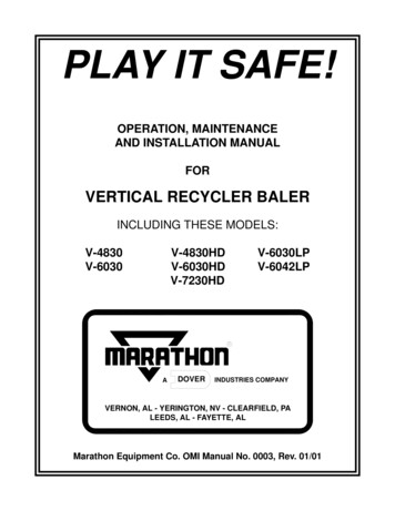
Installation, Operation and Maintenance Manual4.5 AUTOMATIC AIR RELEASE VALVE (AARV)The AARV is designed to allow ventilation of air during the priming cycle. Once thepump is primed, the AARV will close due to the discharge pressure generated by thepump. A small amount of liquid (1 to 5 gallons per minute) will still bypass when thevalve is in the closed position. Each AARV size must be chosen and adjusted for itsspecific application. Each AARV must be sized and adjusted forits specific applicationThe AARV is installed in the discharge line between the discharge flange and inlet sideof the check valve as shown in figure 2. The inlet must be installed below the center lineof the AARV. The discharge of the valve must be safely directed back to the sumpappropriate vessel through a bleed line. The bleed line must slope towards the sump orvessel and be one inch or larger in size.Figure 4-24.6 ALIGNMENTAlignment of the driver to the pump is imperative to the operating life of the equipment.Misalignment can lead to bearing failures, coupling wear, and shortened V-belt life.Power sources mounted by Summit Pump are aligned prior to shipment. Shipping andhandling may cause misalignment. Units must be checked prior to operation.Pump rotation is clockwise when viewed from driven end of the pump8SUMMIT PUMP MODEL SN
Installation, Operation and Maintenance Manual4.71.2.3.4.DIRECT COUPLED PUMPUse flexible spacer couplings to achieve proper alignment.Check and adjust the parallel and angular alignment to within .005 inches prior toconnecting the coupling halves.Check that driver rotation agrees with pump rotation. The pump shaft rotationshould be clockwise when viewed from the drive end.Install a coupling guard when alignment is complete.4.8BELT DRIVEN PUMPLocate driver shaft parallel to pump shaft. Aline the sheaves and belt tensioner toproperly set up V-belts. A solid shaft must be used in all enginedriven applications. Note: Solid shaftsrequire an extra spacer.SUMMIT PUMP MODEL SN
Installation, Operation and Maintenance Manual5ASSEMBLY PROCEDURES5.1 ROTATING ASSEMBLY(See Appendix A & B for Cross-Section of pump, rotating assembly and cartridgemechanical seal)To assemble a rotating assembly:1.Clean the disassembled bearing housing (199);2.Secure the bearing frame to bench or holding stand;3.Install vent, oil and cavity plugs (409, 410, 414, 415,416);4.Install sight glass (319)5.Install outboard bearing (118) on shaft (106) retaining ring towards end ofshaft;6.Install inboard bearing (116) on shaft (106);7.Install outboard lip seal (149) in bearing cap (237);8.Install inboard lip seal (147) in bearing housing (199);9.Slide shaft bearing assembly into bearing housing (199) from drive end offrame until outboard bearing retaining ring is in its groove in frame;10.Slide bearing cap (237) and gasket (601) over shaft (106);11.Insert bearing cap bolts through cap (237) and gasket (601).12.Install shaft o-ring (412).13.Slide gasket (606) and back seal plate (184) over impeller end of shaft;14.Install bolt (377) and lock washer (344) into bearing frame (199) and backseal plate (184) and tighten;15.To install mechanical seal (189), install the sleeve o-ring (412) to the step ofshaft (106). Lubricate stationary seat o-ring with P-80 Thix rubber lubricantgel. Using the recommended oil noted in the “Lubrication” section on page18, place one drop
SUMMIT PUMP MODEL SN iii WARRANTY Pumping units assembled by Summit Pump, Inc., Green Bay, WI are guaranteed to be free from defects in material and workmanship for