Transcription
Chilled Water Pump Calculator GuideTable of Contents1.0 Introduction . 21.1 Units . 22.0 Disclaimer . 23.0 Overall Chilled Water System . 24.0Chilled Water Pump Calculator - Inputs . 44.1Fluid Information . 44.2Pipe Information . 54.3Valve & Fitting Information . 64.4Equipment Information . 64.5Pipe Expansions & Reductions Information . 75.0Chilled Water Pump Calculator - Outputs . 75.1Fluid Velocity . 75.2Reynolds Number . 85.3Friction Factor . 85.4Pressure Drop . 95.4.1Pressure Drop – Piping & Valves/Fittings . 95.4.2Pressure Drop – Equipment . 105.4.3Pressure Drop – Expansions/Reducers . 106.0Chilled Water Pump Schedule . 126.1Flow Rate (GPM) . 136.2Total Dynamic Head (Feet Head) . 136.3Service . 136.4Location . 136.5Pump Types . 136.6Pump Efficiency . 156.7Pump Speed . 166.8Motor . 166.9Remarks, Additional Features . 18Chilled Water Pump-1http://www.engproguides.com
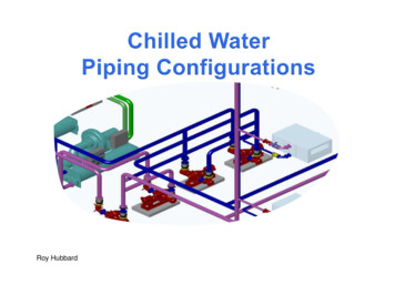
1.0 INTRODUCTIONThe purpose of this guide is to provide the necessary background information on the ChilledWater Pump calculator to be able to use the calculator and to fill out a chilled water pumpschedule. This guide covers the overall chilled water system, the calculator and the chilledwater pump schedule. The overall chilled water system will help you to visualize how the chilledwater pump fits within the overall system and will also help you to determine the hydraulicallyremote run for pressure drop calculations. Following the overall chilled water system, theinputs, outputs and references used in the calculator will be covered. The primary purpose ofthe calculator is to find the total dynamic head for use in the Chilled Water Pump Schedule.Lastly, each individual item within the Chilled Water Pump Schedule will be discussed in orderto give you more knowledge on how to complete the schedule for your specific chilled waterpump application.1.1 UNITSThe primary units that are used in the calculator are United States Customary System Units(USCS). As such, this guide focuses exclusively on the USCS. However, an SI version willalso be provided in the future.2.0 DISCLAIMERIn no event will Engineering Pro Guides be liable for any incidental, indirect, consequential,punitive or special damages of any kind, or any other damages whatsoever, including, withoutlimitation, those resulting from loss of profit, loss of contracts, loss of reputation, goodwill, data,information, income, anticipated savings or business relationships, whether or not EngineeringPro Guides has been advised of the possibility of such damage, arising out of or in connectionwith the use of this guide/software or any referenced documents and/or websites.This guide and calculator were created on the basis of helping engineers to increase theirefficiency in completing calculations. However, the book and calculator was not intended toreplace the engineering judgment necessary to interpret the results of any calculations. Theengineer is still responsible for the calculations and results within the calculator.3.0 OVERALL CHILLED WATER SYSTEMThis guide covers the design and selection of a chilled water pump. The chilled water pump is apart of an overall chilled water system that often includes a chiller, piping, valves/fittings,expansion tank, air handling units and fan coil units. The chilled water pump is used to circulatechilled water in a closed system. The chilled water pump circulates return chilled water from theair handling units & fan coil units back to the chiller. The chiller then cools the chilled water andthe chilled water is then supplied back to the air handling units and fan coil units.Chilled Water Pump-2http://www.engproguides.com
The chilled water pump must be sized properly to circulate the correct amount of flow at thecorrect pressure in order to achieve proper cooling within the building. If there is insufficientflow and pressure, then there will not be enough cooling and the building may get hot duringperiods of high cooling load. If there is too much pressure and flow, then the electrical systemwill be unnecessarily burdened and if there is no speed control, then electricity may be wasteddue to excess pumping.Figure 1: This figure shows an overall chilled water system. The chilled water pump circulates chilledwater through the system.Chilled Water Pump-3http://www.engproguides.com
4.0 CHILLED WATER PUMP CALCULATOR - INPUTSIn order to best use the chilled water pump calculator you should have an understanding of theinputs and how changes in the inputs will affect the output.4.1FLUID INFORMATIONThe fluid information required includes the fluid type, temperature, density andkinematic/dynamic viscosity.Figure 2: The fluid information section is the first set of inputs required for an output from the calculator.Fluid Type: There are several fluid types of available for use in the calculator, including water,propylene glycol mixtures and ethylene glycol mixtures. If you select a fluid type from the dropdown menu and a temperature, then the calculator will automatically fill in the properties fordensity, dynamic viscosity and kinematic viscosity. If your fluid type is not available in the dropdown menu, then you must manually input all the values into the calculator, in order for thecalculator to work.Temperature: The temperature is used by the calculator to automatically find the density,dynamic viscosity and kinematic viscosity from the fluid properties built-in to the calculator. Ifyou are not using one of the drop-down fluid types, then the temperature is not necessary to getan output from the calculator.The typical chilled water temperatures are shown below. You should select the lowest supplychilled water temperature. Supply Chilled Water: 42 F to 48 F/5.56 C to 7.78 CReturn Chilled Water: 52 F to 58 F/5.56 C to 7.78 CDensity: The density is used in the calculations to find the Reynolds Number. The ReynoldsNumber is used to find the friction loss coefficient.Chilled Water Pump-4http://www.engproguides.com
Dynamic Viscosity: The dynamic viscosity is used in the calculator to find the ReynoldsNumber.4.2PIPE INFORMATIONThe calculator requires you to insert the pipe section information which includes the flow rate,pipe material, pipe type, pipe size and length of pipe. A different pipe section should be used ifany of these variables are changed.Figure 3: The pipe information is used to find the inner area and relative roughness of the piping.There are various pipes available for use in the calculator but you can also add your own pipeinformation. The pipes built-in to the calculator include ASTM A53 Steel (Schedule 40 & 80),ASTM B88 Copper (Type K, L & M), ASTM D2241 PVC (SDR 26) and ASTM F2389Polypropylene (DR 9). These are the most common pipes used in chilled water pipeapplication. If you have a special case, then please use the references sheet to add in yourpipe information or contact Justin via email contact@engproguides.com.Figure 4: This figure is a sample of the pipe information built-in to the calculator, references tab.Each pipe material and pipe type within that pipe material have its own standard pipe sizes. Forexample, Schedule 40 Steel does not have a 5/8 inch pipe size. When you change pipeChilled Water Pump-5http://www.engproguides.com
materials and pipe types, please also change the pipe size to ensure the pipe size you want isavailable within the standard. The calculator will give you an error if you select a non-standardpipe size within the pipe material & type.4.3VALVE & FITTING INFORMATIONThe valves and fittings section requires you to put in the values for each fitting that are on acertain pipe section. A pipe section is defined as having the same flow rate and same pipeinformation.Figure 5: Inputting the valves and fittings on a piping section will help to determine the total loss throughthe piping section.The valve and fitting quantities are matched to 3-K values within the references tab. If you havea special valve and fitting, you can add in the 3-K values to the references tab. If you don’t havethe 3-K values you can either choose a similar valve/fitting or you can estimate the pressuredrop and add this to the equipment information section.4.4EQUIPMENT INFORMATIONThe equipment section requires you to insert the flow rate and pressure drop for each piece ofequipment. You should also indicate if the equipment is on the hydraulically remote run.Remember, only items listed as hydraulically remote will be used to calculate the pressure dropfor the chilled water pump.Figure 6: The pressure loss due to equipment is specific to the manufacturer of the equipment. Youshould check the manufacturer product data for this information, but you should also remember that theChilled Water Pump-6http://www.engproguides.com
pressure loss is specific to a certain flow rate. If your flow rate is different, then you will need to adjust thepressure drop to match your application.4.5PIPE EXPANSIONS & REDUCTIONS INFORMATIONPipe expansions and reductions use different equations to calculate pressure drops than thoseused for pressure loss through straight length of piping and through valves & fittings. Pipeexpansion and reductions are dependent on the ratio between the two different pipe diameters.For example, the pressure drop through a 4”- 6” pipe expansion is less than the pressure dropthrough a 2” – 6” pipe expansion.Figure 7: Pipe expansion and reductions are different from valves and fittings.5.0 CHILLED WATER PUMP CALCULATOR - OUTPUTSThis section covers the equations that use the inputs and references to create the outputs in thecalculator.5.1FLUID VELOCITYThe first equation uses the inputs from the pipe information section and the user input flow rateto find the fluid velocity in the pipe. When you choose the pipe material, pipe type and pipesize, the calculator will automatically determine the inner area from the table within thereferences. If the combination of pipe material, pipe type and pipe size is not in the calculatorthen a “N/A” will appear in the velocity column. You should double check to make sure thecombination exists before proceeding.Chilled Water Pump-7http://www.engproguides.com
7.481 160sec5.2REYNOLDS NUMBERThe first equation uses the inputs from the pipe information section and the user input flow rateto find the fluid velocity in the pipe. When you choose the pipe material, pipe type and pipesize, the calculatorThe next equation calculates the Reynolds Number. This equation uses the velocity from theprevious equation along with the pipe inner diameter and the fluid properties (density &viscosity). secThe Reynolds Number classifies the fluid flow into either (1) Laminar, (2) Transition or (3)Turbulent. The breakdown between these three classifications is defined below. The frictioncalculations are most accurate with fluid flow in the turbulent region. For this reason, thecalculator will highlight in red any Reynolds Number that is below the turbulent region. 2,000 5.32,00010,00010,000FRICTION FACTORThe friction factor is found through the Colebrook Equation. The Colebrook Equation relates thefriction factor to the Reynolds Number and the relative roughness.12 log2.513.72
pipe material, pipe type, pipe size and length of pipe. A different pipe section should be used if any of these variables are changed. Figure 3: The pipe information File Size: 1MBPage Count: 18