Transcription
Heat Pump Installation, Maintenanceand Service ManualThis booklet is to be carefully read and instructions followed forefficient and trouble free operation of theRheem Thermal Swimming Pool Heat Pump43 Marigold StreetRevesby NSW 2212Tel: (02) 9684 3684Fax: (02) 9684 3698ABN 28 062 383 22427/5/2019
TABLE OF CONTENTSINTRODUCTION .1SECTION 1INSTALLATION .2Site Location, Preparation & Unit Positioning . 2Plumbing . 3Chemical Treatment . 3Electrical . 4Control Design for Pool Heating . 4Link between Heat Pump, Water Pump and Thermostat for Pool Heating . 4Precautions . 5SECTION 2COMMISSIONING .6SECTION 3OPERATION .6Thermostat Operation . 7Heat Up Time . 7De-Icing. 7Pool Application . 7SECTION 4MAINTENANCE .7Heat Exchanger Care . 8Service Assistance . 8SECTION 5TROUBLESHOOTING .9Machine Will Not Start . 9Pool Will Not Heat . 9Compressor Will Not Run . 9Compressor Motor Hums But Will Not Start. 9SECTION 6INSTALLATION SCHEMATIC DRAWINGS .10Typical Single Pool Heat Pump Schematic For Pool Filtration .10Typical Single Pool Heating Schematic .10Typical Multiple Pool Heat Pump Installation .11SECTION 7WARRANTY .12
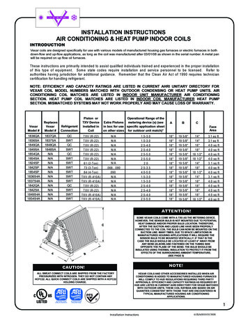
INTRODUCTIONRheem Thermal Pool Heat Pumps are available in sizes from 9kW to 540kW nominal output. Theunits are most commonly manufactured as air-to-water design, in which it extracts heat from ambientair and transfer it into the water, to provide the most cost efficient method of water heating. The unitscan also be manufactured as water-to-water or ground-coupled design.Each is a fully packaged unit, requiring only electrical and water connections to be made oninstallation.Each is factory charged, with refrigerant R407 being ideally suited for commercial or industrialsituations requiring 40 C for pool heating. Rheem Thermal also manufactures hot water heat pumpswith R410A and R134A may be used for special hot water applications.The Rheem Thermal heat pump is installed to a wide diversity of commercial and industrialapplications. The performance of the unit varies with ambient operating conditions, water flow, andwater temperature and as such, selection should be done in conjunction with an experienced heatpump dealer or the manufacturer.Each Rheem Thermal unit is manufactured to meet specific task/site requirements and a wide rangeof options is available in unit design.It is characteristic of heat pumps to form ice on the evaporator at cool ambient temperatures. Assuch, various de-ice mechanism options are provided.This manual includes important information in regards to installation, operation, maintenance andservicing and should be retained for the life of the heater. Correct installation and familiarity with theoperational guidelines is important.
SECTION 1INSTALLATIONFor validity of the Rheem Thermal warranty, installation must be carried out by registered tradeperson.Delivery Reference should be made to the unit specifications to determine weight and lifting requirements. Packaging materials should be removed upon delivery so to avoid any sweating of the electricalcompartment or potential staining to the case, particularly in tropical areas.Site Location, Preparation & Unit Positioning Heat Pump heating efficiency and output increases with the rise in entering air temperature andas such, it is not necessary for the unit to be placed in sunlight in the manner of a solar heatingsystem. On the other hand, direct sunlight to the evaporator may provide a marginal increase inheat transfer and would assist in the removal of ice formation in cold climate locations. Locating the Heat Pump close to other system equipment like filter, pump, tank, etc. will minimisefriction and heat losses. It is important that the Clearance Guidelines included in this Manual are read and understood.These guidelines set out the minimum clearance requirements in respect of air flow andservicing. Free circulation of air across the coil, requires no obstructions on the intake or fan discharge ofHeat Pumps. In addition, care should be taken to ensure that walls, eaves, etc. do not obstructthe release of discharge air such that this may recirculate in the incoming air stream of the unit. For the plant-room installation, make sure that sufficient fresh air is available via provision of inletgrills in building design, etc. Exhaust air from the Heat Pump must be discharged by a duct awayfrom the fresh air supply. Never install in an enclosed area. Service access is required at both ends of the Heat Pump as per the Clearance Guidelines (Seeattached) Where multiple units are to be installed, minimum clearance requirements increase. The Heat Pump requires a firm base, say concrete slab. Rubber mounts should be installedbetween the unit and slab. Drainage of condensate and entering rain water will occur at drainage points provided at theplumbing end of the unit. To ensure proper drainage, make sure that the unit is located at aslightly tilted angle with the drain on the downhill side of the unit. This can be done by makingthe concrete slab slightly higher at one end or lifting one end of the unit by rubber mounts,noting that the larger units include inbuilt 50mm fall. If the unit is to be installed internally, it isrecommended that it sit within a separate drip tray, with provision for drainage of this water to adrain, etc. Ideally, the condensate drain provision connected to the heat pump drip tray or tothe drainage points in the heat pump should be flexible and able to be readily removed forcleaning. Clear plastic connections at the drain will allow the owner to check that debris/dustetc. has not restricted the condensate drains. It is important that water is not allowed to pondwithin the unit so as to avoid corrosion to the base of the compressor or heat exchangers. Local building authorities should be consulted for regulations concerning minimum installationdistance from pool or other amenities. Units to be used in areas having corrosive atmospheres should be specified at time of ordering. Consideration should be given to the operating noise, wherever possible the exhaust should bedirected away from the occupied areas.2
Plumbing It is preferable that the heat pump is connected to filtered water. It is essential that the water recirculating pump and pipe sizes be engineered to suit the particularapplication, giving correct water flow through the heat pump as per the specification requirementsof the unit. Inadequate or excessive water flow detracts from heating efficiency and can lead todamage to the unit. Selection of the recirculating pump must be made in accordance with thedesign flow rate and pressure as per the pump manufacturer’s specification. If unsure, contact Rheem Thermal for recommendations on the optimum flow rate. Assistancewill be provided where possible in relation to plumbing design and pump selection. Water connections on the unit are clearly marked as water inlet and water outlet. The installation of breakable unions on both inlet and outlet pipes will facilitate maintenance andwater drainage of the system. If the unit is situated below the pool level or an open holding tank,shut off valves should be fitted on the water side of both unions so that removal of the machineis possible without draining the system. A separate circuit is generally the most desirable plumbing configuration with individual flow andreturn line and filter strainer. This may not always be possible particularly with established pools. Heat pumps may be plumbed in-line with existing filter equipment, although thought must begiven to correct flow, run time and possible over chlorinating and/or dosing by extended runningof automatic chlorinator, feeders, etc. Typical plumbing schematics for installation with existingfiltration and with a dedicated heating circuit are shown in Section 6. A one-way check valve should be installed on the outlet of the heat pump. Models without an internal water flow by-pass must have an external by-pass fitted. Where multiple units are installed, the heaters must be installed in parallel to equalise pressuredrops and balance flow through the heaters. Systems of two or more Heat Pumps require amanifold. All Plumbing should be carried out by qualified tradesman (plumber).Chemical TreatmentRheem Thermal heat pumps designed for swimming pool or spa heating will include a titanium heatexchanger. This material is impervious to chemical corrosion and as such, variations in water qualitywill not cause damage to the titanium tube. However, it is recommended as a matter of good poolmanagement that the correct chemical balance of the water be maintained as follows: pH to be kept between 7.2 and 7.8Alkalinity must not exceed 200 PPMFree available chlorine must not exceed 6.0 PPMChemicals must be added downstream side of the Heat Pump.In line chlorinator must be installed downstream of the Heat Pump.The maintenance of the above guidelines does not in itself ensure that water is in balance and noncorrosive. Various mechanisms are available to monitor water conditions and information on theLanglier Saturation Index is provided as a commonly applied industry standard.3
Electrical All electrical work must be carried out by licensed electricians and all the wiring should be carriedout to AS/NZS3000 latest edition wiring standards. Refer to the internal electrical wiring diagram supplied with the units before proceeding withelectrical work. As a minimum, cable and fuse sizing must be correct relative to the unit’sspecified requirements. Rheem Thermal’s technical specification for each model nominateselectrical demand information and minimum circuit size. An isolating switch must be fitted adjacent to the Heat Pump To connect power, remove the electrical service panel. Enter wire through the conduit entrance.Ground to lug. Line voltage to contactor terminals L1 and L2 and L3 if unit is three phase. L1and N for single phase. Water must be running through the unit before it is able to be switched on.Control Design for Pool HeatingHeat pumps intended for individual installation to a pool are manufactured with in-built thermostatcontrol and flow switch. The thermostat is mounted either on the outside panel or internally in the compressorcompartment. The controller displays entering water temperature, with the sensor being locatedin a well to the inlet water pipe inside the unit. The flow switch is a safety feature to ensure that the Heat Pump runs only when there is adequatewater flow. If water flow is disturbed by backwashing, etc., or inadequate, the unit will lock-outby this safety feature. The unit must be manually reset, by turning OFF, then ON. (SeeTroubleshooting). In commercial settings, it is important that the heat pump is isolated during backwashing to avoidlock-out or potential short-cycling. Ideally, the unit would be switched off, either at the mainswitch, the isolating switch located on or adjacent to the unit or at a control sub-board.For systems comprised of multiple Heat Pump units, the thermostat sensor and well may be providedas follows depending on client requirement: Provided loose to allow installation of thermostat controller display in heat pump control panel(located separately to the heat pumps) with well and probe installed in the pool pipe work on theinlet side of the heat pumps or balance tank. Provided in the nominated lead-unit (i.e. the control heat pump) with relays fitted to the lag unit(s)to allow control wiring to be run to these units.Link between Heat Pump, Water Pump and Thermostat for Pool HeatingThe thermostat sensor is the controlling device in the heating system. This determines whether theheat pump unit should run and is activated in response to the parameters set for pool temperaturecontrol. That is, the heat pump will run when the entering water temperature (EWT) is less than thedesired set point (normally with a -0.5 C split) and stop running when the EWT is a set point. Insimple terms, this means that the heat pump must be provided with constant water flow in order toachieve temperature measurement. Likewise the heat pump will not run without water flow.In situations where the heat pump is installed into the existing pool filtration system, the operation ofthe heat pump will be controlled by pool temperature at times when the recirculating pump is running.If the recirculating pump is time-clocked to suit filtration routines, then the period of power supply tothe filter pump may need to be progressively expanded with cooler air temperatures (as the heaterwill need to run longer hours than filtration needs in cooler months). If not automated, chlorinationsettings may also need adjustment.4
By contrast, in warmer months the heat pump will run less hours than the filter. The heat pump maybe left ON, (i.e. with power supply), as it will only run if the pool temperature falls below the desiredset point by -0.5 C.Where the Heat Pump is installed on a separate heating circuit (i.e. separate recirculating pump),the ideal scenario is that a control logic/interface is in place between the heat pump and therecirculating pump. That is, flow is provided only when heating is required so that the pump use islimited strictly to those hours needed to maintain the pool temperature.The Rheem Thermal heat pump may be provided with pump-call or a pump control function so thata run signal is provided to the pump via the heat pump’s controller based on temperature signals.PRECAUTIONSWhere damage to property can occur in the event of the heat pump leaking, the unit must beinstalled in a drained drip tray in accordance with AS/NZS3500.4 and local codes andregulatory authority requirements.The heat pump must be maintained in accordance with the Owners Guide and InstallationInstructions.If the heat pump is to be used in a commercial application, you should ensure that you haveadequate redundancy within the heating system. This should ensure the continuity of heatingin the event that the heat pump should become inoperable for any reason. We recommendthat you seek advice from your Rheem Thermal representative or your specifier about yourneeds and building redundancy into your heating system.In operating your heat pump, you should ensure that the hydraulic layout of the system iscorrect. Particular care should be given to ensure that excess pressure is not created to theheat pump’s internal heat exchanger(s).5
SECTION 2COMMISSIONINGThe Rheem Thermal heat pump is fully charged with refrigerant. The following checks should becarried out:1. Installation and operation instructions should be read prior to commissioning.2. The unit should have unrestricted supply of fresh air to the coil and exhaust air removed fromclosed in areas.3. The unit should stand on a firm level base but noting that it should have a small incline towardsthe condensate drainage inbuilt to the case (plumbing end).4. Noise should be directed away from living areas.5. Water connected correctly as indicated.6. Any chemicals are introduced downstream of unit.7. Condensate drain runs to waste.8. Unit is wired correctly.9. Unit is not to be started without flow of water.10. The thermostat is set to the required parameters.11. Three phase fans and scroll compressors are running in correct rotation.SECTION 3OPERATION1. The Heat Pump unit has an internal thermostat, located at the control panel, which maintains theoutlet water at the selected temperature. The normal operating temperature range is 25 C to40 C.2. Select a suitable temperature about 38 C for spa and 28 C for pools.3. The unit is fully automatic and after commissioning, the operation of the unit will be triggered bywater flow and the set temperature parameters.4. In low ambient temperature ice may form on the evaporator coil. If this occurs the machine willautomatically go into defrost operation.5. The unit can be controlled via time-clock through water pump. The unit has in-built waterflow/pressure switch and will sense water flow to start unit.6. Running Time The Heat Pump is controlled by a thermostat which will switch the unit off whenthe set temperature is reached. The running time will vary with the weather, amount of wind,length of time the pool cover is off and the pool usage. As this is an automatic operation, manualswitching is not necessary, i.e. allow the Heat Pump to monitor the pool temperature. Longperiods of being switched off will make the unit’s job more difficult, especially when a constanttemperature is desired.7. Backwashing – Always isolate the unit electrically prior to backwashing.8. Valve Setting – Do not adjust any valves whilst the pump is running.Note that the initial temperature rise for swimming pool heating may seem slow but the unit isprobably working. Heat pumps have a much lower KW/MJ per hour heat output capacity than gasand will need to operate for more time to deliver the same heat transfer.6
Thermostat OperationAs a guide, your heat pump is fitted with the Rheem IQ tariff intelligent control – Please refer to theRheem IQ Tariff Controller, user manual provided inside the unit. The relevant Carel Rheem IQ operating manuals should have been provided to you with deliveryof the heater. If these have not been received, please contact us directly and we will be pleasedto provide copies.Heat Up TimeHeat up time on pool and spa will vary depending on outside air temperature, wind speed over pool,amount of sun on pool, unit size and running time available.To maintain temperature and reduce running cost a heat retention blanket must be used overnightor whenever pool or spa is not in use.De-IcingPool ApplicationRefrigerant hot gas by-pass is intended for locations where ice build-up on cool
Heat Pump Installation, Maintenance and Service Manual This booklet is to be carefully read and instructions followed for efficient and trouble free operation of the Rheem Thermal Swimming Pool Heat Pump 43 Marigold Street Revesby
