Transcription
Simplifying technology, redefining valueHYDRO-PNEUMATICRECIPROCATING PUMPMANUAL
CONTENTSINTRODUCTIONGENERAL DESCRIPTIONPRINCIPLES OF OPERATIONTYPICAL APPLICATIONSINSTALLATION AND COMMISSIONINGPREVENTIVE MAINTENANCE &TROUBLESHOOTINGSECTION ASSEMBLY DRAWINGRECOMMENDED SPARES1
INTRODUCTIONWe are very much thankful to you to purchase our unique, simplified, newly developedHydro Pneumatic Reciprocating Pump. We are also very much thankful to you for keepingtrust in us by getting our indigenously developed product in your working area.Please read this Manual carefully before commissioning the pump.The Manual describes the working, installation, troubleshooting and other informationrequired for satisfactory performance and maintenance of our equipment.Our “DUTTA” make Hydro Pneumatic Reciprocating Pump is the result of extensive developmenteffort carried out to achieve well design, good overall service life and ease of maintenance.Our Hydro Pneumatic Reciprocating Pump is a very reliable product, which will run for severalyears with a minimum preventive maintenance. In the failure of product, we request you to studythe manual carefully in which troubleshooting instructions are given, before calling for service.We believe in constantly improving our product and we look forward to your valued Suggestions,critical comments and observations which will help us in improving our product further.The manual describes theory of working, installation, commissioning, trouble shooting andother information required for satisfactory performance and maintenance. In the event of failure/breakdown at Pump, please read this manual thoroughly before calling for Service.2
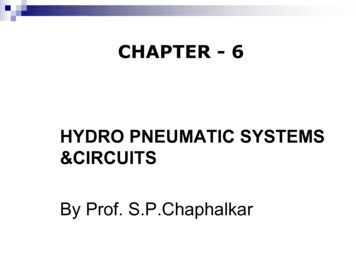
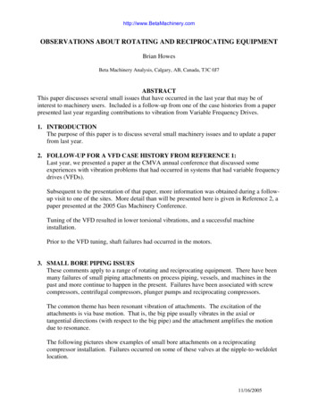
GENERAL LAYOUT OF PUMP INSTALLATIONWATER TANK MOUNT 100mmABOVE SUCTION N.R.V.5/2 PILOT-PILOTMASTER VALVESILENCERSREGULATOR FOR ADJUSTINGOUTPUT PRESSUREFRL-500 UNITSUCTIONSTRAINERTO LOCKPUSHTOLOCKP US H3/2 HANDSLIDE VALVESUCTION N.R.V.INBLEED HOLEOUTNOTE:DISCHARGE N.R.V.TO3/2 PILOTVALVEMARKED ITEMS ARE NOT SUPPLIED BY US.MARKED ITEMS ARE NOT PART OF PUMP& WILL BE BILLED SEPARATLY.SYSTEMFIG. -A3
GENERAL DESCRIPTIONThe general layout of components used in proper installation of our Hydro PneumaticReciprocating Pump is given in Fig. A. The principle of operation is given in Fig. B, Fig. C, Fig. D.NOTE:-Items marked * are not in our scope of supply for the pump assembly. The FRL isto be bought separately.ADVANTAGES OF DUTTA MAKE HYDRO-PNEUMATIC PUMPS:Dutta make Hydro-Pneumatic Reciprocating Pumps are an efficient, low cost alternative toMotorized & hand operated pumps. Our salient features are as follows: 4It is compact and lightweight in construction.4It has flexibility / adaptability for mounting in any direction.4It has low air consumption. When used in conjuction with a low pressure high dischargecentrifugal prefill pump, the energy consumption and time for building desired pressure is verylow. Once pressure has built up there is no further consumption of compressed air.4Once the desired set pressure is achieved, pump will stop & will run only to compensate theleakage if any. This action of pump is achieved automatically, thus preventing any excessivepressure than the desired pressure & there is no need of restarting pump in case of any leakage.4Pump can be operated in hazardous location as it is operated by compressed air.4It is designed for use with water & other non-corrosive liquids, as all wetted parts are made fromstainless steel.4
INTENSIFIER-SDIA. D2AREA A2DIA. D1AREA A1P2P1 x A1 P2 x A2. . P2 P1 x A1A2INTENSIFICATION RATIO A1A2P1AIR PRESSURE REGULATORAIR INLETFIG-BINTENSIFIER-DDIA. D2AREA A2DIA. D1AREA A1P1 x 2A1 P2 x A2P1. . P2 P1 x 2A1AIR PRESSURE REGULATORA2INTENSIFICATION RATIO 2A1A2FIG-CPNEUMATIC CIRCUIT DIAGRAMFOR HYDROPNEUMATIC RECIPROCATING PUMP3/2 PLUNGER SPRING PILOT VALVEWATER TANKSUCTION STRAINERA2A1SUCTION NON RETURN VALVEDISCHARGE NON RETURN VALVEP2P13/2 PLUNGER SPRING PILOT VALVESILENCER5/2 PILOT-PILOT MASTER VALVEAIR PRESSURE REGULATORFIG-D5
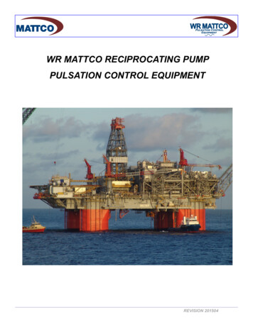
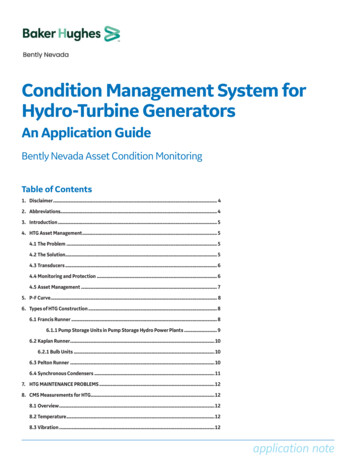
PRINCIPLES OF OPERATIONThe heart of DUTTA MAKE Hydro-Pneumatic Reciprocating Pumps is an air to liquid Intensifierwhich is diagrammatically shown in Fig. B.The Pneumatic cylinder of large diameter D1 is coupled to a hydraulic cylinder of small diameter D2.When regulated compressed air at pressure P1 is applied on D1, the pressure P2 of liquid in D2increases as per Pascal's Law.P1 x A1 P2 x A2Where A1 4 x D12.x D2and A2 . . P2 P1 x A1/A24The ratio A1/A2is called the intensification ratio.2For high ratio pumps, area A1 is increased by coupling two pneumatic cylinders D1 to a single hydrauliccylinder D2 as shown in Fig. C. Low pressure, low ratio pumps are called Intensifier-S (Fig. B.) andhigh pressure, high ratio pumps are called Intensifier-D (Fig. C.) pumps can be identify by the lastalphabetic in the model number.The air to liquid intensifier shown in Fig. B & Fig. C. is converted into a pump by automaticallyreciprocating the pneumatic cylinder by suitable valves as shown in Fig. D.When regulated air at pressure P1 is supplied through 5/2 pilot-pilot master Valve A, the cylinderpiston starts moving to the right. When the piston presses the 3/2 Valve B, a pilot signal is given to theright end of Valve A, causing it to reverse & the cylinder piston starts moving to the left. When the pistonpresses 3/2 Valve C, a pilot signal is given to left end of Valve A, causing it to reverse & the piston startsmoving to the right. Hence pneumatic piston starts reciprocating continuously as long as compressedair is supplied.On the liquid side of the pump, a suction & discharge non-return valve is fitted. When the pistonmoves to the left, vacuum is created in the hydraulic cylinder & liquid is sucked in due to theopening of suction non-return valve. When the piston moves to the right, the suction non returnvalve shuts & the sucked liquid is discharged through the discharge non-return valve. The constantreciprocation of the cylinder causes suction & discharge of liquid in pulses. The discharged liquid isfed into the product, which has to be pressurized.As liquid fills into product, pressure starts rising & when it reaches value P2, the forces in pump balance& pump stops reciprocating automatically to compensate for Leakaqe & maintain output pressure P2.6
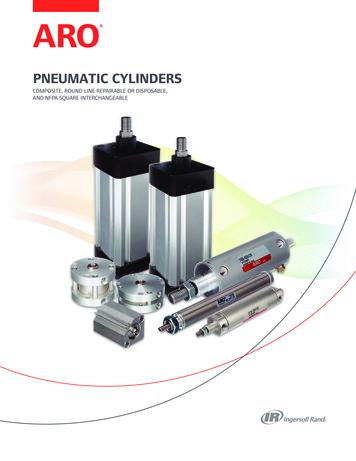
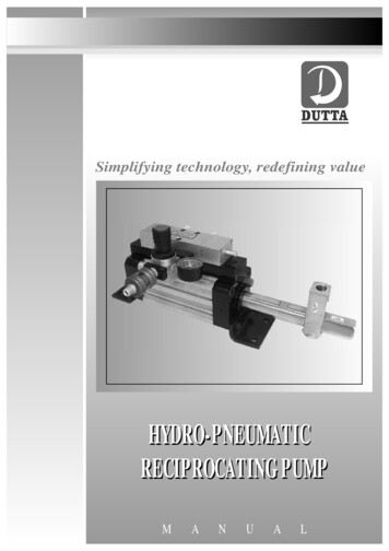
7HYDRO PNEUMATIC PUMPFRL UNITFIG-EP2PRODUCT UNDER TESTISOLATION VALVENON RETURN VALVENON RETURN VALVESUCTION STRAINERWATER TANKDRAIN VALVENON RETURN VALVEPREFILL CENTRIFUGAL PUMPTYPICAL PRESSURE TESTING UNIT
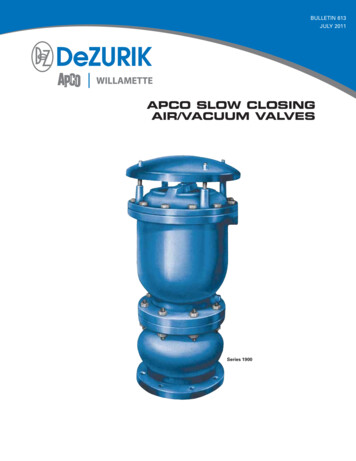
TYPICAL APPLICATIONS8HYDROSTATIC PRESSURE TESTING:One of the most popular applications of “DUTTA MAKE” Hydro Pneumatic Reciprocating pumps arefor pressure / burst testing of Castings, Valves, Hoses, Pressure Vessels etc. The general layout of ahydrostatic pressure testing setup is shown in Fig. E.The product under test (ex. Casting) is first prefilled with water using a high discharge“CENTRIFUGAL PUMP”. When all trapped air escapes & the casting is fully filled, the“DRAIN” valve& the “CENTRIFUGAL PUMP” are switched “OFF” & the “HYDRO PNEUMATIC PUMP” is switched“ON” When pressure in gauge P2 rises to the value set in regulator P1, the “ISOLATION” valve isclosed & after a slight delay the “HYDROPNEUMATIC PUMP” is switched “OFF”. Any leakage in theproduct is detected by drop in pressure gauge P2.The drain valve is opened to release pressure & drain the water after completion.8OTHER APPLICATIONS OF TESTING:Some of the applications where “DUTTA MAKE” Hydro Pneumatic Reciprocating Pumps can be used asa low cost alternative to hand operated & motorized hydraulic pumps: -Seat leakage test of control valves.4Burst Strength Testing of pressurized vessels such as LPG / Nitrogen / Oxygen gas cylinders,storage tanks, hoses, pipes etc.4Cyclic pressure / life testing of Pressure Gauges, Pressure Switches, Hoses etc4Metered filling of liquid products such as soft drinks, juices, medicines etc. in packaging machines.4Transferring of liquids from barrels, storage tank etc.4Operation of single acting hydraulic cylinders used in lifting platforms, hydraulic clamps,compression molding presses etc.4Isostatic pressing of powder metals & ceramics.4Pumping of oil or grease in centralized lubrication8
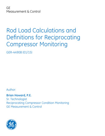
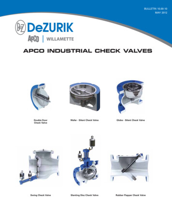
TECHNICAL SPECIFICATIONSAIR INLET"K" BSP"H" BSPDISCHARGE PORTM(MAX)"J" BSPSUCTION PORTDAE"L" 4HOLESφFOR MOUNTINGBFCGFIG - FOutput Pr. atMODEL NO. RATIO 5Kg/sq.cmABCDEFGHBSPJBSPKBSPφMLFREEFREE AIRDISCHARGE 1001931/2"1/2"1/2"172631.013309
INSTALLATION AND COMMISSIONING1.INSTALLATION:Refer to Fig. A for general installation layout and Fig. F. for overall dimensions1.1 Mount the pump using the four mounting holes provided. The Pump can be mountedhorizontally, vertically, or at any angle.1.2 Connect filtered, regulated, & lubricated ( FRL Set ) air supply to the inlet port on hand slide valve.CAUTION: - The pump will fail prematurely if proper lubrication is not provided.1.3 Ensure that the lubricator is filled with Hydraulic Oil. Set the lubricator in such a way that 2-3drops of oil falls for every minutes.The following grades of oil must be used: HYDROL 32(Bharat Petroleum)SERVO SYSTEM 32(Indian Oil Corporation)ENKLO 32(Hindustan Petroleum)CAUTION: - Do not use any oil other than those recommended above. The seals may reactchemically with some grades of oil.1.4 Ensure that the inlet air supply to the FRL unit & from FRL unit to inlet of Pump has a minimumI.D. of 6mm for series 80 & series 100 pumps & I.D. of 13 mm for series 160 pump. It should beNoted that the distance of FRL from pump should not be more than 2.5 meters.1.5 Connect inlet water / oil supply from an overhead tank mounted preferably at least 100mm abovepump. If applications demands that the tank has to be placed below the pump, then a footvalve has to be fitted in the suction line to avoid periodic priming.1.6 Ensure that a 100mm mesh suction strainer is fitted in the liquid inlet line.1.7 Ensure that the I.D. of the suction line is atleast 13mm for ½” BSP connection & 20mm for ¾”BSP connection. A smaller line or restricted suction line will create cavitation & the pump willrun inefficiently.1.8 Pipe the pump outlet to the system with suitable pipes / hoses which can withstandtwice the pressure generated by the pump.10
2 COMMISSIONING: -2.1 Slide 3/2 Hand Slide Valve backward to shut air supply to the pump.2.2Rotate Regulator knob Turn anti-clockwise fully to achieve zero pressure condition.2.3 Open main air supply. Set the regulator of FRL Unit to maximum of 6 Kgf/cm²2.4 Slide 3/2 Hand Slide Valve forward.2.5 Gradually rotate clockwise regulator knob again .As the pressure rises the pump will startreciprocating first slowly and then rapidly as the air pressure increases.2.6 After a few strokes water / oil will start flowing freely in pulses from outlet hose. Shut the outletline with a suitable valve. The pressure will immediately rise in the outlet line.2.7Adjust the regulator for the required value of outlet pressure.2.8 While the pump is reciprocating, observe the rate of oil flow from the lubricator. Set theLubricator as instructed in point 1.3 (1)2.9 After the testing is over, shut the air supply by sliding the hand slide valve backwards. Open thedrain valve in discharge line to release pressure.11
PREVENTIVE MAINTENANCE &TROUBLESHOOTINGPREVENTING MAINTENANCE8DAILY4Keep test & pump area clean. Wipe dry excess water /oil which might have splashed during testing.4Ensure that the water /oil in the tank is clean.4Observe oil level in the lubricator. The lubricator should be atleast ½ full.CAUTION: - Ensure that the pump is not operated if the lubricator is empty. The pump willfail prematurely if it is run without lubrication.4If the pump is used continuously and lubricator is set correctly as per instructions in point 1.3 (1)then lubricator should get empty in 1 week. If excess lubrication is released then a spray of oil willcome from two exhaust silencers of the pump. If this happens then shut the lubricator fully andrun the pump till spray of oil from valve exhaust ports stops. Now reset the lubricator as instructedin point 1.3 (1)4When the pump is not in use, switch off air supply by sliding the 3/2-hand slide valve backwards.8WEEKLY4Observe the leakage of liquid from bleed hole (Fig. A.). If there is excessive leakage then a sealwill need replacement & order the spare seal kit before total breakdown takes place.4Observe for leakage from joints in non-return valve assembly.8MONTHLY4Replace the water / oil in the tank.4Clean the tank and suction strainer before filling fresh water / oil.8YEARLY4Replace the 2 exhaust silencers.4Clean / Replace suction strainer in water / oil tank.4Check the condition of pneumatic and hydraulic hoses and replace if necessary.12
THREE YEARS84Replace the all rubber parts in the pump and valves. It is recommended that even though sealsare not leaking after three years of installation, they should be replaced as properties of rubberparts deteriorate with time.4Replaces bonded washer of Non return Valves. Check the i
Dutta make Hydro-Pneumatic Reciprocating Pumps are an efficient, low cost alternative to Motorized & hand operated pumps. Our salient features are as follows: - 4It is compact and lightweight in construction. 4It has flexibility / adaptability for mounting in any direction. 4It has low air consumption.