Transcription
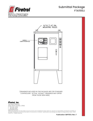
Submittal PackageFTA1100JMark IIXG Diesel EngineFire Pump Controllers(DRAWINGS INCLUDED IN THIS PACKAGE ARE FOR STANDARDCONTROLLERS. ACTUAL “AS BUILT” DRAWINGS MAY DIFFERFROM THOSE SEEN HERE).3412 Apex PeakwayApex, North Carolina 27502P 919 460-5200F 919 460 5250www.firetrol.comWhile every precaution has been taken to ensure accuracy and completeness herein, Firetrol, Inc. assumes no responsibility, and disclaims all liability, fordamages resulting from use of this information or for any errors or omissions. Specifications and drawings are subject to change without notice. 2019Firetrol, Inc., All Rights Reserved.Publication SBP1100J Rev. F
Firetrol Mark IIxg Diesel Engine Fire Pump ControllerFTA1100J - 12 or 24 VoltSpecifications1.0 Main Fire Pump ControllerThe main fire pump controller shall be a factory assembled, wired and testedunit. The controller shall be of the combined manual and automatic type designed for diesel engine operation of the fire pump.1.1 Standards, Listings & ApprovalsThe controller shall conform to all the requirements of the latest editions of:NFPA 20, Standard for the Installation of Stationary Pumps for Fire ProtectionNFPA 70, National Electrical CodeThe controller shall be listed by:Underwriters Laboratories, Inc., in accordance with UL218, Standard for Fire PumpControllers Canadian Standards Association CSA-C22.2, Standard for IndustrialControl Equipment (cUL)The controller shall be approved by:Factory Mutual (IEC 62091)1.2 EnclosureThe controller components shall be housed in a NEMA Type 2 (IEC IP22) dripproof, wall mounted enclosure.1.3 Operator InterfaceThe fire pump controller shall feature an operator interface with user keypad.The interface shall monitor and display motor operating conditions, including allalarms, events, and pressure conditions. All alarms, events, and pressure conditions shall be displayed with a time and date stamp. The display shall be a128x64 Backlit LCD capable of customized graphics. The display and interfaceshall be NEMA rated for Type 2, 3R, 4, 4X, and 12 protection and shall be fully accessible without opening the controller door. The display and user interface shallutilize multiple levels of password protection for system security. A minimum of 3password levels shall be provided.1.4 Digital Status/Alarm MessagesThe digital display shall indicate text messages for the status and alarm conditions of: Engine Run Remote Start Min. Run Time / Off Delay Time Manual EngineCrank Engine Fail To Start Electric Control Module (ECM) Warning Drive NotInstalled ECM Failure Disk Error Low Suction Pressure PLD (Pressure Limiting Driver) Sequential Start Time High Raw Water Temp. Crank/Rest TimeCycle Clogged Raw Water Strainer Low Engine Temp. Interstitial/FuelSpill Disk Near Full Pressure ErrorThe Sequential Start Timer and Minimum Run Timer/Off Delay Timer shall be displayed as numeric values reflecting the value of the remaining time.
1.5 LED Visual IndicatorsLED indicators, visible with the door closed, shall indicate: AC Power Available Alarm Main Switch in Auto Main Switch In Manual System Pressure Low Engine Running Engine Fail To Start Engine Temperature High Engine Oil Pressure Low Engine Overspeed Engine AlternateECM Engine Fuel Injector Malfunction Fuel Level Low Automatic ShutdownDisabled Charger Malfunction Battery #1 Trouble Battery #2 Trouble1.6 Data LoggingThe digital display shall monitor the system and log the following data: Motor Calls/Starts Pump Total Run Time Pump Last Run Time Total Controller Pwr On Time Last Pump Start Min/Max System Pressure Last High Temperature Last Low Oil Pressure Last Engine Overspeed Last Low Fuel Level Last Charger Fail Last Battery Trouble Battery #1 Volts(Min./Now/Max.) Battery #2 Volts (Min./Now/Max.) Battery #1 Amps (Min./Now/Max) Battery #2 Amps (Min./Now/Max.)1.7 Event RecordingMemory - The controller shall record all operational and alarm events to systemmemory. All events shall be time and date stamped and include an index number. The system memory shall have the capability of storing 3000 events andallow the user access to the event log via the user interface. The user shall havethe ability to scroll through the stored messages in groups of 1 or 10.1.8 USB Host ControllerThe controller shall have a built-in USB Host Controller. A USB port capable of accepting a USB Flash Memory Disk shall be provided. The controller shall save alloperational and alarm events to the flash memory on a daily basis. Each savedevent shall be time and date stamped. The total amount of historical datasaved shall solely depend on the size of the flash disk utilized. The controller shallhave the capability to save settings and values to the flash disk on demand viathe user interface.1.9 Serial CommunicationsThe controller shall feature a RS485 serial communications port for use with 2 or4 wire Modbus RTU communications.2.0 Solid State Pressure TransducerThe controller shall be supplied with a solid state pressure transducer with arange of 0-300 psi (0-20.7 bar) 1 psi. The solid state pressure switch shall beused for both display of the system pressure and control of the fire pump controller. Systems using analog pressure devices or mercury switches for operational control will not be accepted.The START, STOP and SYSTEM PRESSURE shall be digitally displayed and adjustablethrough the user interface. The pressure transducer shall be mounted insidethe controller to prevent accidental damage. The pressure transducer shall bedirectly pipe mounted to a bulkhead pipe coupling without any other supportingmembers. Field connections shall be made externally at the controller couplingto prevent distortion of the pressure switch element and mechanism.2.1 Seismic CertificationThe controller shall be certified to meet or exceed the requirements of the 2012International Building Code and the 2013 California Building Code for ImportanceFactor 1.5 Electrical Equipment for Sds equal to 1.88 or less severe seismic regions.Qualifications shall be based upon successful tri-axial shake-table testing inaccordance with ICC-ES AC-156. Certification without testing shall be unaccept-
able. Controller shall be clearly labeled as rated for installation in seismic areasand a Certificate of Conformance shall be provided with the controller.2.2 Controller OperationA digitally set On Delay (Sequential Start) timer shall be provided as standard.Upon a call to start, the user interface shall display a message indicating theremaining time value of the On Delay timer.The controller shall be field programmable for manual stop or automatic stop.If set for automatic stopping, the controller shall allow the user to select either aMinimum Run Timer or an Off Delay Timer. Both timers shall be programmablethrough the user interface.The controller shall include an AC Power Loss start timer to start the engine in theevent of AC Power failure.A weekly test timer shall be provided as standard. The controller shall have theability to program the time, date, and frequency of the weekly test. In addition,the controller shall have the capability to display a preventative maintenancemessage for a service inspection. The message text and frequency of occurrence shall be programmable through the user interface.A Lamp Test feature shall be included. The user interface shall also have theability to display the status of the system inputs and outputs.An Audible Test feature shall be included to test the operation of the audiblealarm device.2.3 Battery ChargersThe controller shall include two fully automatic, 200 amp hour, 4 step batterychargers. The chargers shall feature a qualification stage, in which the batteriesare examined by the charger to insure that they are not defective and are capable of accepting a charge. The battery charger shall feature: Selectable AC Power Voltage Selectable Battery Voltage Selectable Battery Type Charge Cycle Reset Push-button2.4 ManufacturerThe controller shall be a Firetrol brand.3412 Apex PeakwayApex, North Carolina 27502P 1 919 460 5200F 1 919 460 5250www.firetrol.comWhile every precaution has been taken to ensure accuracy and completeness herein, Firetrol, Inc. assumes no responsibility, and disclaims all liability, for damages resulting from use of this information or for any errors or omissions. Specifications and drawings are subject to change without notice. 2019 Firetrol, Inc., All Rights Reserved.Publication SP1100-50 Rev. F
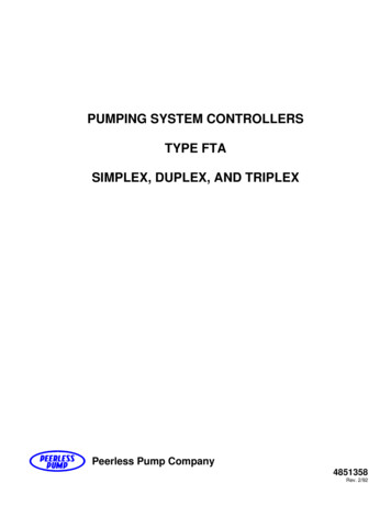
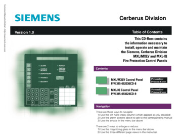
Product DescriptionMark IIxg Diesel Engine Fire Pump ControllerDescription – Firetrol combined automatic andmanual Mark IIXG based diesel engine fire pumpcontrollers are intended for starting and monitoring fire pump diesel engines. They are suitablefor use with both mechanical and electronictype engines. The controller is available for 12or 24 volt negative ground systems, using leadacid or Nickel-Cadmium batteries. The controllermonitors, displays and records fire pump systeminformation.Approvals – Firetrol fire pump controllers arelisted by Underwriters’ Laboratories, Inc., in accordance with UL218, Standard for Fire PumpControllers, CSA, Standard for Industrial ControlEquipment (cUL), and approved by FactoryMutual. They are built to meet or exceed therequirements of the approving authorities aswell as NEMA and the latest editions of NFPA 20,Installation of Centrifugal Fire Pumps, and NFPA70, National Electrical Code.Standard Features – The following are includedas standard with each controller: AC Line & Battery circuit breakers Manual-Off-Auto selector switch Manual test push-button Two manual crank push-buttons Two 10 Amp battery chargers with 4 stage charging cycle, selectable AC voltage (110 / 220),selectable DC voltage (12 / 24), and selectablebattery type (Lead Acid, Ni-Cad 9/18 Cell, Ni-Cad10/20 Cell) Door mounted display/interface panel featuringa 128 x 64 pixel backlit LCD graphical display,Membrane Type User Control Push-buttons andeasy to read LED Indicators for: AC POWER AVAILABLE ALARM MAIN SWITCH IN AUTO MAIN SWITCH IN MANUALFTA1100J SYSTEM PRESSURE LOW ENGINE RUNNING ENGINE FAIL TO START ENGINE TEMPERATURE HIGH ENGINE OIL PRESSURE LOW ENGINE OVERSPEED ENGINE ALTERNATE ECM ENGINE FUEL INJECTOR MALFUNCTION FUEL LEVEL LOW AUTOMATIC SHUTDOWN DISABLED CHARGER MALFUNCTION BATTERY #1 TROUBLE BATTERY #2 TROUBLE Minimum Run Timer / Off Delay Timer Programmable Daylight Saving Time Option Weekly Test Timer Engine Run Time Meter Digital Pressure Display USB Host Controller and Port Solid State Pressure Transducer Data Log Event Log (3000 events) Simultaneous Display of Battery Voltages, Charging Rates, AC Volts, Pressure and Alarm Messages Disk Error Message Disk Near Full Message Pressure Error Message Fail to Start Message Low Suction Pressure Message Crank Cycle Status Indication (Displays CrankingBattery, Number of Starting Attempts and Crank/Rest Time Remaining) 300 psi (20.7 bar) wet parts (solid state pressuretransducer, solenoid valve, plumbing) for freshwater applications NEMA Type 2 enclosure (IEC IP22) Each standard controller comes with user setoptions for: AC Power Loss Start Interlock Alarm Low Pressure Aud. Low Suction Main Sw. Mis-Set Manual Test Pump Run Alarm Remote Start User Defined Input Weekly Test Setup Low Pump Rm Temp Low Reservoir Relief Valve Open High Fuel Level High Reservoir Also included (as required) are Audible/Visiblealarm notifications for: Electronic Engine Control Module (ECM) Warning Electronic Engine Control Module (ECM) Failure Low Engine Temperature High Raw Cooling Water Temperature Low Raw Water Flow (Clogged Stainer) Fuel Spill (Interstitial Space Liquid Intrusion) Low Suction Pressure (At Variable Speed SuctionLimiting Engine Controls)
Product Description - Options & ModificationsSpecial Enclosures-EEnclosuer, NEMA Type 4 (IEC IP 66), Painted Steel-FEnclosure, NEMA Type 4X (IP66), #304 Stainless Steel,Brushed Finish-FDEnclosure, NEMA Type 4X (IP66), #316 Stainless Steel,Brushed Finish-FDBEnclosure, NEMA Type 4X (IP66), #316 Stainless Steel,12 Gauge, Seam Welded, Brushed Finish-FDPEnclosure, NEMA Type 4X, #316 Stainless Steel,Painted Finish-FXPEnclosure, NEMA Type 4X (IP66), #304 Stainless SteelPainted Finish-GEnclosure, NEMA Type 12 (IP54), Painted Steel-TEnclosure, NEMA Type 3R (IP24), Painted SteelMounting Legs-N31 Mounting Legs, Standard 12 Inch, Painted Steel-N31S Mounting Legs, Standard 12 Inch, Stainless SteelAnti-Condensation Space Heaters-HSpace Heater, 120V Externally Powered with CircuitBreaker-JSpace Heater, 120V Externally Powered with CircuitBreaker and Thermostat-KSpace Heater, 120V Externally Powered with CircuitBreaker and Humidistat-LSpace Heater, 240V Externally Powered with CircuitBreaker-M Space Heater, 240V Externally Powered with CircuitBreaker and Thermostat-N Space Heater, 240V Externally Powered with CitcuitBreaker and HumidistatPressure Transducers, Solenoid Valves, Plumbing-BWetted Parts Including Pressure Sensor, 600 PSI (42 Bar),Fresh Water-C Wetted Parts Including Pressure Sensor, 300 PSI (21 Bar),Sea Water-D Wetted Parts Including Pressure Sensor, 600 PSI (42 Bar),Sea WaterAlarms-AC Alarm Output Contacts, Extra, Engine Running (3 Sets)-AJ Alarm Output Contacts, Engine Overspeed-AK Alarm Output Contacts, Low Oil Pressure-ALAlarm Output Contacts, High Water Temperature-AM Alarm Output Contacts, Fail To Start-AN Alarm Output Contacts, Battery / Charger Failure-AP Alarm Output Contacts, Main Switch In Manual-AR Alarm Output Contacts, Main Switch In Off-AS Alarm Output Contacts, Main Switch In Auto-AT Alarm Output Contacts, Pump Room Trouble1-AV Alarm Output Contacts, Low Pump Room Temperature1-AW Alarm Output Contacts, Reservoir Low1-AY Alarm Output Contacts, Low Suction Pressure1-COM Alarm, Audible/Visible/Output Contacts, Low SuctionPressure with Manual Reset Option. P
Description – Firetrol combined automatic and manual Mark IIXG based diesel engine fire pump controllers are intended for starting and monitor - ing fire pump diesel engines. They are suitable for use with both mechanical and electronic type engines. The controller is available for 12 or 24 volt negative ground systems, using lead