Transcription
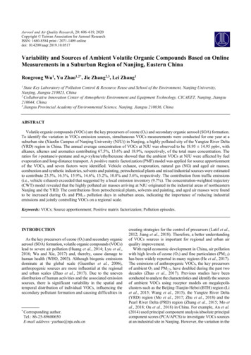
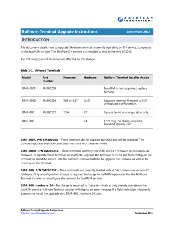
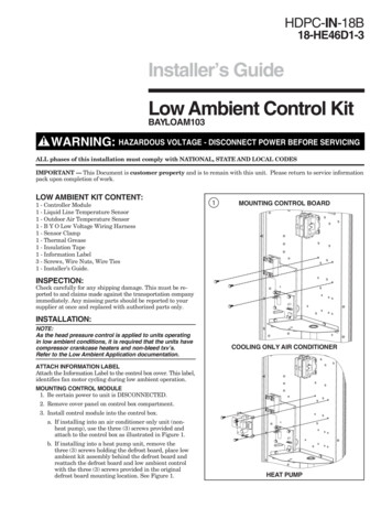
HDPC-IN-18B18-HE46D1-3Installer’s GuideLow Ambient Control KitBAYLOAM103WARNING: HAZARDOUS VOLTAGE - DISCONNECT POWER BEFORE SERVICINGALL phases of this installation must comply with NATIONAL, STATE AND LOCAL CODESIMPORTANT — This Document is customer property and is to remain with this unit. Please return to service informationpack upon completion of work.LOW AMBIENT KIT CONTENT:1 - Controller Module1 - Liquid Line Temperature Sensor1 - Outdoor Air Temperature Sensor1 - B Y O Low Voltage Wiring Harness1 - Sensor Clamp1 - Thermal Grease1 - Insulation Tape1 - Information Label3 - Screws, Wire Nuts, Wire Ties1 - Installer’s Guide.1MOUNTING CONTROL BOARDINSPECTION:Check carefully for any shipping damage. This must be reported to and claims made against the transportation companyimmediately. Any missing parts should be reported to yoursupplier at once and replaced with authorized parts only.INSTALLATION:NOTE:As the head pressure control is applied to units operatingin low ambient conditions, it is required that the units havecompressor crankcase heaters and non-bleed txv’s.Refer to the Low Ambient Application documentation.COOLING ONLY AIR CONDITIONERATTACH INFORMATION LABELAttach the Information Label to the control box cover. This label,identifies fan motor cycling during low ambient operation.MOUNTING CONTROL MODULE1. Be certain power to unit is DISCONNECTED.2. Remove cover panel on control box compartment.3. Install control module into the control box.a. If installing into an air conditioner only unit (nonheat pump), use the three (3) screws provided andattach to the control box as illustrated in Figure 1.b. If installing into a heat pump unit, remove thethree (3) screws holding the defrost board, place lowambient kit assembly behind the defrost board andreattach the defrost board and low ambient controlwith the three (3) screws provided in the originaldefrost board mounting location. See Figure 1.HEAT PUMP
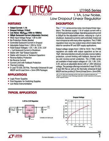
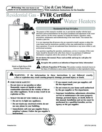
Installer’s GuideMOUNTING LIQUID LINE TEMPERATURE SENSOR4. Remove the service access panel to the left side of thecontrol box of the air conditioner or heat pump.6. Route the sensor leads through the low voltage accesshole and attach to the two (2) pin connector provided onthe control board. See Figure 3.5. Attach the liquid line sensor to the liquid line:a. If installing on a cooling only air conditioner unit,attach the liquid line sensor to the liquid line near thedrier assembly. Apply thermal grease (supplied) to theliquid line, where the sensor will be mounted. Usingthe clamp provided, attach the sensor as shown;Figure 2A. When completed, wrap the completeassembly with the insulation tape.3b. If installing on a heat pump unit, attach the liquidline sensor to the liquid line running vertically,directly behind the control box. Apply thermal grease(supplied) to the liquid line, where the sensor will bemounted. Using the clamp provided, attach the sensorassembly as shown; Figure 2B. When completed, wrapthe complete assembly with the insulation tapeprovided.2LIQUID LINE TEMPERATURE SENSORCONTROL BOX SENSOR WIRING ROUTINGA) COOLING ONLY AIR CONDITIONERB) HEAT PUMP 2004 American Standard Inc. All Rights ReservedAPPLY CLAMP TO SENSOR AND LIQUID LINE18-HE46D1-3
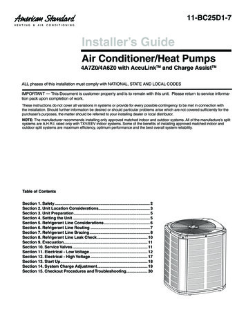
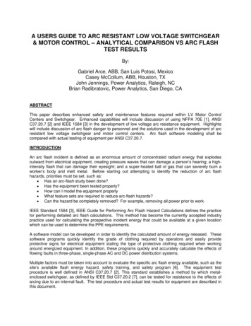
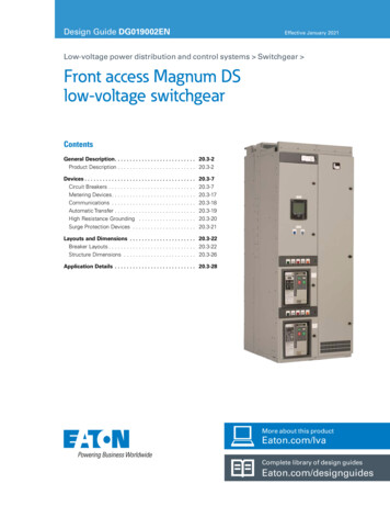
Installer’s GuideMOUNTING OUTDOOR TEMPERATURE SENSOR7. Using pliers, bend the corner of the control box basedownward, to create an opening for the sensor leads. SeeFigure 4.4OUTDOOR TEMPERATURE SENSOR8. Route the sensor, from the control board, down throughthe opening created in the control box base. With wire tieprovided, secure the sensor to the low voltage wiring orconduit below the control box base. Place the wire tie onthe sensor wires (not on the sensor) and dress so that thetemperature sensing area is not in direct contact withany surrounding surfaces and is not in direct sunlight.WIRING CONTROL MODULE9A) Cooling Only Air Conditioner Models: See Figure 5Disconnect the black fan motor lead from the contactor(This wire is attached to contactor terminal “T2”, with aquick connect terminal). Reconnect this fan motor lead tothe black wire from the solid state relay on the controlmodule. This wire has a sleeved, 1/4" male tab forattaching to the fan motor wire terminal.Connect the other black wire from the solid state relay tothe contactor terminal “T2” (from where the fan motorlead was disconnected).Low voltage wires:Connect the 3-pin wire assembly to J5 on the controlboard (3-pin male connector).BEND CONTROLBOX CORNERSENSOR WIRE ROUTINGConnect the yellow lead wire to a 1/4" male tab on theright hand side of the main contactor (low voltagecontactor coil terminal).Connect the blue lead wire to the wire nut junction of theblue wire.Connect the orange wire to the wire nut junction of theyellow wire.(New wire nuts are provided)NOTE:To ease the insertion of the connector housing ontothe J5 header, place the connector on the tips of thethree header pins. Angle the connector upward towardthe header latch while pushing connector over theheader pins.518-HE46D1-3AIR CONDITIONING / COOLING ONLY3
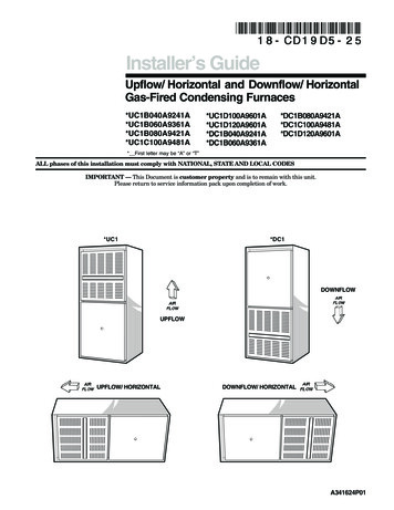
Installer’s Guide9B) 200/230 Volt Heat Pump: See Figure 6Disconnect the black fan motor lead from the defrostboard relay (The black wire is attached to the “N.C.”terminal of the relay).!CAUTIONFIRMLY HOLD RELAY WHEN REMOVING WIRE.Reconnect this fan motor lead to the black wire from thesolid state relay on the control module (This wire has asleeved, 1/4" male tab for attaching to the fan motor leadwire terminal).Connect the other black wire from the solid state relay tothe “N.C.” terminal on the defrost board relay (fromwhere the fan motor was disconnected).Low voltage wires:Connect the 3-pin wire assembly to J5 on the controlboard (3-pin male connector).64NOTE:To ease the insertion of the connector housing on tothe J5 header, place the connector on the tips of thethree header pins. Angle the connector upward towardthe header latch while pushing connector over theheader pins.Connect the yellow lead wire to a 1/4" male tab on theright hand side of the main contactor (low voltagecontactor coil terminal).Connect the blue lead wire to the wire nut junction of theblue wire.Connect the orange lead wire to the wire nut junction ofthe orange wire.(New wire nuts are provided.)200 / 230 VOLT HEAT PUMP18-HE46D1-3
Installer’s Guide9C) 460 Volt Heat Pump Models: See Figure 7Disconnect the black fan motor lead from the fan relay(terminal #6). Reconnect this black motor lead to theblack wire from the solid state relay on the controlmodule (This wire has a sleeved, 1/4" male tab forattaching to the fan motor lead wire terminal).Connect the other black wire from the solid state relay toterminal #6 of the fan relay (from where the fan motorwire was disconnected).Connect the yellow lead wire to a 1/4" male tab on theright hand side of the main contactor (low voltagecontactor coil terminal).Connect the blue lead wire to the wire nut junction of theblue wire.Connect the orange lead wire to the wire nut junction ofthe orange wire.(New wire nuts are provided.)Low voltage wires:Connect the 3-pin wire assembly to J5 on the controlboard (3-pin male connector).NOTE:To ease the insertion of the connector housing ontothe J5 header, place the connector on the tips of thethree header pins. Angle the connector upward towardthe header latch while pushing connector over theheader pins.718-HE46D1-3460 VOLT HEAT PUMP5
Installer’s GuideSYSTEM SETUP10. The control board contains a momentary test switch (S1)and a 4-position installer selectable dip switch (S2).Both components are located in the lower right handcorner of the control board. See Figure 8.Manual Mode (S2 dip switch 4 in “On” position) –The S2 dip switch 1, 2, 3 settings are read by thecontroller and used to determine the liquid temperatureset point whenTEST SWITCH2. and after initial start-up mode completion, i.e., duringthe system control mode (no sooner than six minutesafter Y is applied). The liquid temperature set pointwill not change during system start-up.The test switch provides a means of verifying that the fanmotor is under the control of the Low Ambient Controller. A“Y” signal must be present in order to test the control.Depressing the test switch causes the fan to alternately cycleon (for 3 seconds) and off (for 3 seconds) for a total time of12 seconds. The on/off fan operation may be observed bywatching the fan once the test function has been invoked orby monitoring the head pressure using a gauge set. The LEDon the solid state relay should light when voltage is beingapplied to the fan motor. Once the 12-second test period iscomplete the control resumes normal control operation.DIP SWITCHESThe controller will control to a liquid temperature set pointas determined by the dip switch settings. The dip switch isused:1. To select either Automatic Mode or Manual Modeoperation (S2 dip switch 4 setting).2. To select the liquid temperature set point (S2 dip switch1, 2 and 3 settings).Automatic Mode (S2 dip switch 4 in “Off” position) –The controller determines the approach temperaturebased upon the liquid and ambient temperature readings. The approach temperature liquid temperature –ambient temperature. The approach temperature iscalculated only when the ambient temperature is in therange of 65 to 75 deg. F. and the outdoor fan is oncontinuously. If the controller has not yet acquired anapproach temperature, S2 dip switch 1, 2 & 3 settingsare used for determining the liquid temperature setpoint the same as in Manual Mode. If the controller hasacquired an approach temperature, then the liquidtemperature set point is determined as follows:Liquid Temperature Set Point Approach Temperature 70 deg. F.61. Y is first appliedThe dip switches should be set prior to initial applicationof the Y signal to the controller.The dip switches should be set for each specific HVACsystem based upon the following instructions:Determine Liquid Temperature Set PointReference appropriate high side charging chart for theunit; liquid pressure for cooling units and head pressurefor heat pump units.Locate the high side pressure for 70 deg. F. outdoortemperature at the expected indoor wet bulb temperature. Correct the high side pressure according to thespecific indoor unit being used. For Heat pumpssubtract 7 psi, for cooling only units subtract zero psi.Using the refrigerant properties chart, find the saturation temperature for the calculated liquid pressure.Subtract the anticipated sub-cooling temperature(typically 12 degrees) from the saturation temperature toobtain an estimate of the liquid temperature. Set S2 dipswitch 1, 2 and 3 settings to the nearest liquid temperature set point in the table below.S2 Dip Switch 4;Off – Automatic Mode(recommended setting)On – Manual ModeLIQUID TEMPDIPDIPDIPSET POINT F SWITCH 1 SWITCH 2 SWITCH 370 FOFFOFFOFF76 FOFFOFFON82 FOFFONOFF88 FOFFONON94 FONOFFOFF100 FONOFFON106 FONONOFF112 FONONON18-HE46D1-3
Installer’s Guide8CONTROL TS2-1,2,3,4DIP SWITCHESS1TESTSWITCHLEDSThe control board contains two LEDs; one green and one redsurface mount. The green LED is a status indicator labeledLitePort on the control board and flashes at a 1/2 second on(plus fast blink at the end for LitePort data) and 1/2 secondoff rate in the cooling mode. In the heating mode the greenLED is full on with a blink/flicker OFF (LitePort datatransmission) every second.SYSTEM CHECK-OUT – COOLING UNITS ONLYVerify that the control module is installed and wired per theinstructions contained within this installer’s guide. (J5-Blueconnected to “B”, J5-Yellow connected to “Y”, J5-Orangeconnected to “Y”, Liquid sensor installed and connected,ambient sensor installed and connected).If uncertain about S2 dip switch 1, 2, 3, 4 settings, leave inthe factory preset position.The red LED is a small surface mount component locatednear the end of the large capacitor. The red LED is labeledALERT on the control board. The red LED indicator isnormally off. If the red LED is on or flashing then a fault isindicated according to the following:Apply power to the unit. Apply “Y” control signal.Red LED Flashing 1/10 Second ON – 1/10 Second Off –Liquid Sensor FaultThe fan should run continuously for a minimum of 10 seconds after “Y” is applied. After 10 seconds the control maybegin to cycle the fan if the ambient outdoor temperature is70 deg. or below. If the fan is cycling and the outdoor temperature is below 70 deg., the control is working. If after10 seconds of “Y” application the fan is on continuously, theTEST Switch (S1) may be used to verify the Control Modulehas control over the fan. Momentarily depress the TESTSwitch (S1) on the control board. The fan should then cycle3 seconds on then 3 seconds off for 12 seconds.Red LED Flashing 1/2 Second ON – 1/2 Second Off – AmbientSensor FaultRed LED continuously ON – I2C EEPROM Fault boardfailure which cannot be field repairedIf the cause of a fault is cleared or repaired then the red LEDfault indication will clear with the removal and reapplicationof 24 VAC power (Y) to the control.The solid state relay on the control module also contains agreen LED indicator. This LED indicates when the solidstate relay is energized by the control. If the control is cyclingthe fan then this LED will be on/off accordingly.18-HE46D1-3Verify the green LED is flashing at 1/2 second ON 1/2 secondOFF rate.Verify no red LED faults are present.NOTE:If the green LED on the control board is full on with a blink/flicker OFF every second make certain the orange wirefrom the control board is connected to “Y” per theseinstructions.7
Installer’s GuideSYSTEM CHECK-OUT – HEAT PUMPVerify that the kit is installed and wired per the instructionscontained within this installer’s guide. (J5-Blue connected to“B”, J5-Yellow connected to “Y”, J5-Orange connected to “O”,Liquid sensor installed and connected, Ambient sensorinstalled and connected).If after 10 seconds of “Y” application the fan is on continuously, the TEST Switch (S1) may be used to verify theControl Module has control over the fan. Momentarilydepress the TEST Switch (S1) on the Control board. The fanshould then cycle 3 seconds on then 3 seconds off for12 seconds.If uncertain about dip switch settings (S2-1, 2, 3, 4), leave inthe factory preset position.NOTE:If the green LED is full on with a blink/flicker OFF everysecond make certain the orange wire from the controlboard is connected to “O” per these instructions and the“O” signal is present.Apply power to the unit. Apply “Y” and “O” control signal.Verify the green LED is flashing at 1/2 second ON 1/2 secondOFF rate.Verify no red LED faults are present.The fan should run continuously for a minimum of 10 seconds after “Y” and “O” have been applied. After 10 secondsthe control may begin to cycle the fan if the ambient outdoortemperature is 70 deg. or below. If the fan is cycling and theoutdoor temperature is below 70 deg., the control is working.The control board will leave the fan ON continuouslyduring heating mode, i.e., No “O” signal present. Thegreen LED is full on with a blink/flicker off every second inthe heating mode.Literature Order NumberHDPC-IN-18BFile NumberUN-SV-ACC-HDPC-IN-18B 07/04SupersedesHDPC-IN-18A 07/03American Standard Inc.6200 Troup HighwayTyler, TX 75711Stocking LocationP.I. Louisville & Webb/Mason-HoustonFor more information contactyour local dealer (distributor)Since the manufacturer has a policy of continuous product and product data improvement, it reserves the rightto change design and specifications without notice.P.I.
a. If installing into an air conditioner only unit (non-heat pump), use the three (3) screws provided and attach to the control box as illustrated in Figure 1. b. If installing into a heat pump unit, remove the three (3) screws holding the defrost board, pl