Transcription
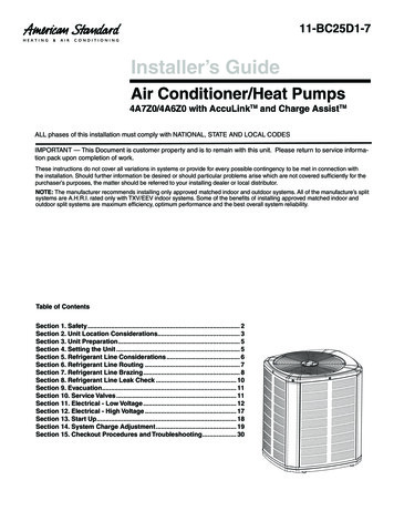
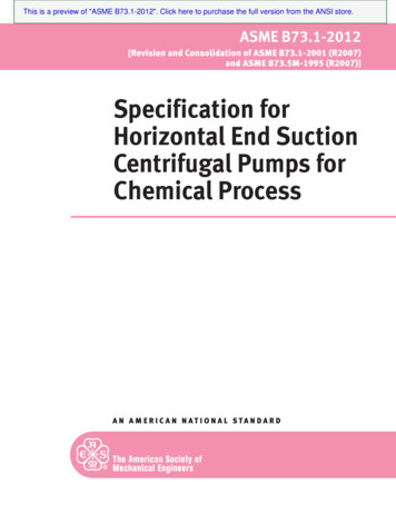
1 8 - CD1 9 D5 - 2 5Installer’s GuideUpflow/ Horizontal and Downflow/ HorizontalGas-Fired Condensing C1D120A9601A* First letter may be “A” or “T”ALL phases of this installation must comply with NATIONAL, STATE AND LOCAL CODESIMPORTANT — This Document is customer property and is to remain with this unit.Please return to service information pack upon completion of work.*UC1*DC1DOWNFLOWUPFLOWUPFLOW/ HORIZONTALDOWNFLOW/ HORIZONTALA341624P01
Installer’s GuideSAFETY SECTIONThe following safety practices and precautions must befollowed during the installation, servicing, and operation of this furnace.1. Use only with the type of gas approved for this furnace. Refer to the furnace rating plate.2. Install this furnace only in a location and position asspecified in “Location and Clearances” (page 4), ofthese instructions.3. Provide adequate combustion and ventilation air tothe furnace space as specified in “Air for Combustion and Ventilation” (pages 8-9), of these instructions.4. Combustion products must be discharged outdoors.Connect this furnace to an approved vent systemonly, as specified in the “Venting” section (pages 1626), of these instructions.5. Never test for gas leaks with an open flame. Use acommercially available soap solution made specifically for the detection of leaks to check all connections, as specified in “Gas Piping” (page 32), of theseinstructions.6. Always install the furnace to operate within thefurnace’s intended temperature-rise range with aduct system which has an external static pressurewithin the allowable range, as specified on the unitrating plate. Airflow with temperature rise for cfmversus static is shown in the Service Facts accompanying this furnace.7. When a furnace is installed so that supply ductscarry air circulated by the furnace to areas outsidethe space containing the furnace, the return airshall also be handled by a duct(s) sealed to the furnace casing and terminating outside the space containing the furnace.8. A gas-fired furnace for installation in a residentialgarage must be installed as specified in “Locationand Clearances” section (page 4), of these instructions.9. The furnace may be used for temporary heating ofbuildings or structures under construction onlywhen the following conditions have been met:a. The furnace venting system must be completeand installed per manufacturers instructions.b. The furnace is controlled only by a room thermostat (no field jumpers).c. The furnace return air duct must be completeand sealed to the furnace and clean air filtersare in place.d. The furnace input rate and temperature risemust be verified to be within nameplate marking.e. 100% of the furnace combustion air requirement must come from outside the structure. 2009 TraneAll Rights Reservedf.The furnace return air temperature range isbetween 55 and 80 degrees Fahrenheit.g. Clean the furnace, duct work, and componentsupon substantial completion of the constructionprocess, and verify furnace operating conditionsincluding ignition, input rate, temperature riseand venting, according to the manufacturer'sinstructions.10. This product must be gas piped by a LicensedPlumber or Gas Fitter in the Commonwealth of Massachusetts.Safety signal words are used to designate a degree orlevel of seriousness associated with a particular hazard.The signal words for safety markings are DANGER,WARNING, and CAUTION.a. DANGER indicates an imminently hazardous situation which, if not avoided, will result in death or serious injury. This signal word is limited to the most extreme situations.b. WARNING indicates a potentially hazardous situationwhich, if not avoided, could result in death or seriousinjury.c. CAUTION indicates a potentially hazardous situationwhich, if not avoided, may result in minor or moderate injury. It is also used to alert against unsafe practices and hazards involving only property damage.! WARNING CARBON MONOXIDE POISONING HAZARDFailure to follow the steps outlined below for each appliance connected to the venting system being placed intooperation could result in carbon monoxide poisoning ordeath.The following steps shall be followed for each applianceconnected to the venting system being placed into operation, while all other appliances connected to the venting system are not in operation:1. Seal any unused openings in the venting system.2. Inspect the venting system for proper size and horizontal pitch, as required in the National Fuel GasCode, ANSI Z223.1/ NFPA 54 or the CAN/ CGA B149Installation Codes and these instructions. Determinethat there is no blockage or restriction, leakage, corrosion and other deficiencies which could cause anunsafe condition.3. As far as practical, close all building doors and windows and all doors between the space in which theappliance(s) connected to the venting system are located and other deficiencies which could cause anunsafe condition.4. Close fireplace dampers.5. Turn on clothes dryers and any appliance not connected to the venting system. Turn on any exhaustfans, such as range hoods and bathroom exhausts,so they are operating at maximum speed. Do not operate a summer exhaust fan.6. Follow the lighting instructions. Place the appliancebeing inspected into operation. Adjust the thermostat so appliance is operating continuously.18-CD19D5-25
7. If improper venting is observed during any of theabove tests, the venting system must be correctedin accordance with the National Fuel Gas Code,ANSI Z221.1/ NFPA 54 and/ or CAN/ CGA B149 Installation Codes.8. After it has been determined that each applianceconnected to the venting system properly ventswhere tested as outlined above, return doors, windows, exhaust fans, fireplace dampers and anyother gas-fired burning appliance to their previousconditions of use.! WARNING FIRE OR EXPLOSION HAZARDFailure to follow the safety warnings exactly could result in serious injury, death or property damage.Improper servicing could result in dangerous operation, serious injury, death, or property damage.GENERAL INSTALLATION INSTRUCTIONSThe manufacturer assumes no responsibility for equipment installed in violation of any code or regulation.It is recommended that Manual J of the Air Conditioning Contractors Association (ACCA) or A.R.I. 230 be followed in estimating heating requirements. When estimating heating requirements for installation at altitudes above 2000 ft., remember the gas input may needto be reduced (See High Altitude Installation).Material in this shipment has been inspected atthe factory and released to the transportationagency without known damage. Inspect exteriorof carton for evidence of rough handling in shipment. Unpack carefully after moving equipmentto approximate location. If damage to contents isfound, report the damage immediately to the delivering agency.Codes and local utility requirements governing theinstallation of gas fired equipment, wiring, plumbing,and flue connections must be adhered to. In the absence of local codes, the installation must conform withlatest edition of the National Fuel Gas Code ANSIZ223.1 National Installation Code, CAN/CGA B149.1.The latest code may be obtained from the American GasAssociation Laboratories, 400 N. Capitol St. NW,Washington D.C. 20001.1-800-699-9277 or www.aga.orgThese furnaces have been classified as CATEGORY IVfurnaces in accordance with latest edition of ANSIZ21.47 CAN/ CGA 2.3 standards.Category IV furnaces operate with positive vent staticpressure and with a flue loss less than 17 percent.These conditions require special venting systems, whichmust be gas tight and water tight. These Category IVDirect Vent furnaces are approved for installation inManufactured/ Mobile housing when used withBAYMFGH100A.18-CD19D5-25Installer’s GuideContentsINSTALLATION INSTRUCTIONSGeneral Installation InstructionsLocation and ClearancesOutline DrawingsUpflow InstallationDownflow InstallationHorizontal InstallationAir For Combustion and VentilationDuct ConnectionsReturn Air FiltersGeneral Venting InstructionsVenting MaterialVenting TablesHorizontal VentingVenting Through The WallVenting Through The RoofDownward VentingVenting Through a Masonry ChimneyCondensate Drain InstructionsElectrical ConnectionsField Wiring DiagramsGas PipingCombustion Input Checks3457778101116161821212525262729293233Start Up and Adjustment35Preliminary InspectionsLighting InstructionsSequence Of OperationControl And Safety Switch AdjustmentsAirflow Adjustment3536363637Abnormal Conditions37IFC Error Flash Code39! CAUTION To prevent shortening its service life, the furnaceshould not be used as a “Construction Heater” duringthe finishing phases of construction until the requirements listed in item 9, a-g of the safety section of thispublication have been met. Condensate in the presence of chlorides and fluorides from paint, varnish,stains, adhesives, cleaning compounds, and cementcreate a corrosive condition which may cause rapid deterioration of the heat exchanger.! CAUTION Do NOT install the furnace in a corrosive or contaminated atmosphere.3
Installer’s GuideLOCATION AND CLEARANCESThe location of the furnace is normally selected by thearchitect, the builder, or the installer. However, beforethe furnace is moved into place, be sure to consider thefollowing requirements:1. Is the location selected as near the vent and as centralized for heat distribution as practical?2. Do all clearances between the furnace and enclosure equal or exceed the minimums shown in theTable 1.3. Is there sufficient space for servicing the furnaceand other equipment? A minimum of 24 inchesfront accessibility to the furnace must be provided.Any access door or panel must permit removal ofthe largest component.4. Are there at least 3 inches of clearance between thefurnace front panel and any closed panel or doorprovided?5. Are the vent pipe and combustion air inlet pipewithin vent table lengths? Will the pipes remain unobstructed?46. Allow sufficient height in supply plenum above orbelow the furnace to provide for cooling coil installation if the cooling coil is not installed at the time ofthis furnace installation.7. A furnace shall be installed so electrical componentsare protected from water.8. If the furnace is installed in a residential garage,it must be installed so that the burners and the ignition source are located not less than 18 inches (46cm) above the floor and the furnace must be locatedor protected to avoid physical damage from vehicles.IMPORTANT:The furnace must be installed level. The only allowablevariation would be slightly to the left and/or forward in upflow installations or slightly toward the front in horizontal installations. This is necessary for proper condensate drainage.18-CD19D5-25
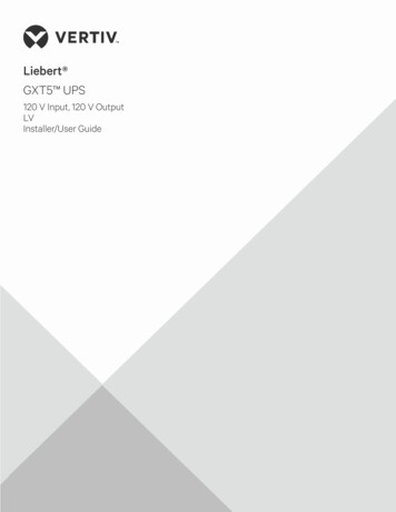
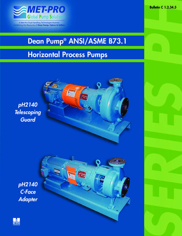
18-CD19D5-25*UC1 OUTLINE DRAWING(ALL DIMENSIONS ARE IN INCHES)Installer’s Guide5
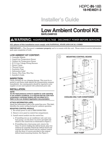
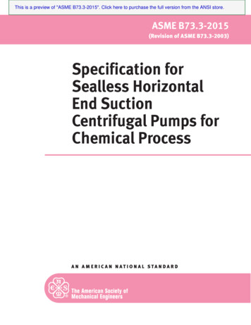
(ALL DIMENSIONS ARE IN INCHES)Installer’s Guide6*DC1 DOWNFLOW/ HORIZONTAL OUTLINE DRAWING18-CD19D5-25
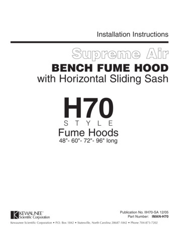
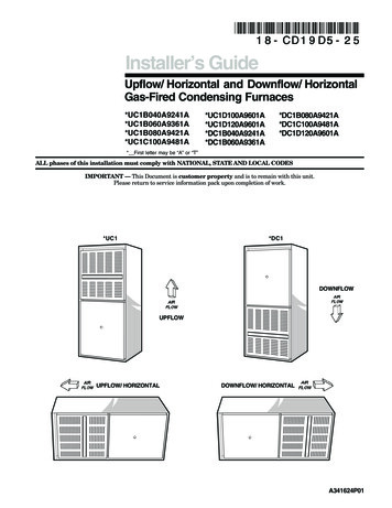
Installer’s GuideTABLE 1UPFLOW INSTALLATIONStandoffs and screws (See Figure 1) are included withthe cased coils for attachment to the furnace. There areclearance alignment holes near the bottom of the coilwrapper. Drill screws are used to engage the furnacetop flanges. The standoff is inserted into the cabinetalignment hole. The drill screws are inserted throughthe standoffs then screwed into the furnace flange.The coil is always placed downstream of the furnace airflow.1DRILL SCREWS (4)STANDOFFS (4)CASECO DILFOR VERTICALINSTALLATIONS:CABINETRETURNWIDTH DUCT WIDTH17-1/2"21"24-1/2"16-1/4"19-3/4"23-1/4"FLOOR OPENING PLENUM /8"HORIZONTAL INSTALLATIONThe coil and furnace must be fully supported when usedin the horizontal position. It is always recommendedthat an auxiliary drain pan be installed under a horizontally installed evaporator coil or 90% gas furnace. Connect the auxiliary drain line to a separate drain line (notrap is needed in this line).Three brackets (with screws) are included with downflow furnaces for installation to stabilize and secure thefurnace and 2/4TXC cased coil in the horizontal position. See Figure 3.IMPORTANT:The 2/4TXC cased coil must be placed downstream of thefurnace. In horizontal installations, the apex of the coilmay point either toward or away from the furnace. Seethe 2/4TXC coil Installer's Guide for more details.4 CASED COIL CONNECTIONSCREWS(BOTH SIDES)UPFU FLORN WACESTANDOFFSBRACKET FOR DOWNFLOWFURNACE IN HORIZONTALDOWNFLOW ONLY(BOTH SIDES)DOWNFLOW INSTALLATIONS! WARNING Do NOT install the furnace directly on carpeting, tile orother combustible material other than wood flooring.For vertical downflow application, subbase (BAYBASE205) must be used between the furnace and combustible flooring. When the downflow furnace is installedvertically with a cased coil, a subbase is not required.Required floor opening:2SUBBASE CROSS 6789012345678901234567890121234567890123456A 456B 6
Duct Connections 10 Return Air Filters 11 General Venting Instructions 16 Venting Material 16 Venting Tables 18 Horizontal Venting 21 Venting Through The Wall 21 Venting Through The Roof 25 Downward Venting 25 Venting Through a Masonry Chimney 26 Condensate Drain Instructions 27 Electrical Connections 29 Field Wiring Diagrams 29 Gas Piping 32 Combustion Input Checks 33 Start Up and