Transcription
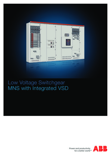
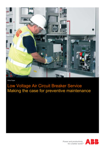
Design Guide DG019002ENEffective January 2021Low-voltage power distribution and control systems Switchgear Front access Magnum DSlow-voltage switchgearContentsGeneral Description. . . . . . . . . . . . . . . . . . . . . . . . . . . . 20.3-2Product Description. . . . . . . . . . . . . . . . . . . . . . . . . . . 20.3-2Devices. . . . . . . . . . . . . . . . . . . . . . . . . . . . . . . . . . . . . .Circuit Breakers . . . . . . . . . . . . . . . . . . . . . . . . . . . . . .Metering Devices. . . . . . . . . . . . . . . . . . . . . . . . . . . . .Communications . . . . . . . . . . . . . . . . . . . . . . . . . . . . .Automatic Transfer. . . . . . . . . . . . . . . . . . . . . . . . . . . .High Resistance Grounding . . . . . . . . . . . . . . . . . . . .Surge Protection Devices . . . . . . . . . . . . . . . . . . . . . youts and Dimensions . . . . . . . . . . . . . . . . . . . . . . . 20.3-22Breaker Layouts. . . . . . . . . . . . . . . . . . . . . . . . . . . . . . 20.3-22Structure Dimensions . . . . . . . . . . . . . . . . . . . . . . . . . 20.3-26Application Details . . . . . . . . . . . . . . . . . . . . . . . . . . . . 20.3-28More about this productEaton.com/lvaComplete library of design guidesEaton.com/designguides
Design Guide DG019002ENFront Access Magnum DS Low-Voltage Switchgear General DescriptionProduct DescriptionProduct Offering Front Access Switchgear UL 1558UL 8912000–6000 A bus800–6000 A breakers100, 150 and 200 kA bus bracing600 Vac classNEMAT 1 indoor (corner sectionavailable for layout flexibility)NEMA 3R outdoor, both aisle andaisleless enclosuresEffective January 202120.3-2Features Application Description Commercial—Office buildings, highrise and convention centersIndustrial—Automotive, petrochemical, pharmaceutical, pulpand paper, utility and data centersInstitutional—Universitiesand hospitalsGovernment—Water treatment,federal buildings and municipalitiesCritical Power OEMs—Generator andUPS manufacturers Standard 40.20-inch (1021.0 mm)switchgear depthUp to 4-high Magnum DS breakerarrangementUp to 8-high Series NRX breakerarrangementBreaker sections are 18, 22, 24 or44 inches (457.2, 558.8, 609.6 or 1117.6mm) wide depending on breaker typeand frame sizesCable compartments are 18, 22, 24, 30or 44 inches (457.2, 558.8, 609.6, 762.0or 1117.6 mm) wide depending on cableor conduit sizesSubstation arrangement, with closecoupling to dry-type or liquid-filledtransformers, where requiredCan be close-coupled to traditionalrear-access switchgearRatingsTable 20.3-1. Voltage Ratings (AC)System VoltageMaximum Voltage208/240480600254508635Table 20.3-2. Available Bus RatingsCross Bus AmpacityMagnum DS Front-Accessible Switchgear40.20-Inch (1021.0 mm) Deep EnclosureThe front-accessible switchgear offer ingallows mounting against a wall, or inother tight locations, where a standardrear-accessible switchgear lineup wouldnot normally fit.Bus Bracing kA200032004000100, 150, 20050006000800010,000100, 150, 200Eaton’s Magnum DS front-accessibleswitchgear combines the robustness ofULT 1558 low-voltage switchgear with theflexibility of UL 891 switchboard design.The three divisions of rear-accessibleswitchgear are redistributed into twovertical sections, with the breaker and thebus in one half and cable and bus in theother half on the right-hand side. Bothsections can be easily accessed byoperators and maintenance personnelfrom the front of the switchgear.EATON www.eaton.com
Front Access Magnum DS Low-Voltage Switchgear General DescriptionOverviewEaton’s Magnum DST power circuitbreaker switchgear is backed by 40 yearsof power circuit breaker and switchgeardevelopment that have set the industrystandards for quality, reliability, maintainability and extended operating life, whenit comes to protecting and monitoringlow-voltage electrical distributionsystems. Magnum DS switchgear isdesigned to meet the changing needsof our customers by providing: Lower installation andmaintenance costsHigher interrupting ratings andwith stand ratingsBetter coordination capabilityIncreased tripping sensitivityEnhanced safety measuresHigher quality, reliability andmaintainabilityCommunications and power qualitymonitoring and measuring capabilitiesFlexible layouts that maximizeuse of capital by minimizingequipment footprintMagnum DS switchgear can meet theneeds of general applications, serviceentrances, harsh environments, multi plesource transfers, special groundingsystems and many others.With a modern design, Magnum DSmetal-enclosed low-voltage switchgearand power circuit breakers provide: 100% rated, fully selective protectionIntegral microprocessor-based breakertripping systemsTwo-step stored-energy breaker closingStandard 100 kA short-circuitbus bracingOptional 150 and 200 kA short-circuitbus bracingOptional metal barriers to isolatethe cable compartment from thebus compartmentBoth indoor and outdoor aisle andaisleless enclosuresFull range of safety solutions dealingwith arc flash hazard and operator errorMany other features for coordinated, safe,convenient, trouble-free, and economicalcontrol and protection of low-voltagedistribution systems are also provided.Magnum DS breakers are designed to:ANSI Standards C37.13, C37.16,C37.17, C37.50 UL 1066 Magnum DS switchgear conforms to thefollowing standards: CSAT C22.2, No. 31-10ANSI C37.20.1ANSI C37.51ULT Standard 1558 and ULStandard 891American Bureau of Shipping (ABS)Built in an ISOT certified facilityDesign Guide DG019002ENEffective January 202120.3-3Through-the-door design: The followingfunctions may be performed without theneed to open the circuit breaker door—lever the breaker between positions,operate manual charging system andview the spring charge status flag,close and open breaker, view andadjust trip unit and read the breakerrating nameplate.Maximum ratings for Magnum DSswitchgear are 600 Vac, 10,000 Acontinuous cross bus and 200,000 Ashort-circuit capacity.Seismic QualificationRefer to www.eaton.com/seismic forinformation on seismic qualification forthis and other Eaton products.Structure FeaturesStandard finish: Gray paint finish(ANSI 61) using a modern, completelyautomated and continuously moni toredelectrostatic powder coating. Thiscontinually monitored system includesspray de-grease and clean, spray rinse,iron phosphate spray coating sprayrinse, non-chemical seal, oven drying,electrostatic powder spray paint coatingand oven curing.Integral base: The ruggedly formed basegreatly increases the rigidity of thestructure, reduces the possibility ofdamage during the installation of theequipment, and is suitable for rolling,jacking and handling. A lifting angleis permanently welded into the buscompartment structure for increasedstrength. The bottom frame structuremembers are indented to allow theinsertion of a pry bar.Through-the-Door DesignCassette design: The breaker cassettesupports the breaker in the cell, as well ason the movable extension rails when thebreaker is placed into or removed fromthe cell. The extension rails allow thebreaker to be drawn out without having tode-energize the entire switchgear lineup.Accessibility: When the door is open orremoved, each breaker compartmentprovides front access to isolated, verticalwireways, primary discon nects, cellcurrent transformers and other breakercompartment accessories for easeof field wiring and trouble shootingfield connections.Heavy-duty door hinges: Each breakerdoor is mounted with hinge pins.Removal of the door is easilyaccomplished by just lifting thehinge pin. This allows easy accessto the breaker internal compartmentfor inspection and maintenance.Breaker CellEATON www.eaton.com
Front Access Magnum DS Low-Voltage Switchgear General DescriptionFour-position drawout: Breakers canbe in connected, test, disconnected orremoved position. The breaker can bemoved between the connected, testand disconnected positions while thecompartment door is closed.Closing spring automatic discharge:Mechanical interlocking automaticallydischarges the closing springs whenthe breaker is removed from itscompartment.Optional safety shutters: Positive actingsafety shutters that isolate the breakerconnections to the main bus when thebreaker is withdrawn from the cell is anoption offered for addi tional safetybeyond our standard design. They reducethe potential of accidental contact withlive bus. Insulating covers (“boots”)are furnished on live main stationarydisconnecting contacts in compart mentsequipped for future breakers.Breaker inspection: When withdrawnon the rails, breaker is completelyaccessible for visual inspection; tiltingis not necessary. The rails are permanentparts of every breaker compartment.Interference interlocks: Supplied onbreakers and in compartments where thecompartments are of the same physicalsize. Interference interlocks ensure anincorrect breaker cannot be inserted.Optional key interlock (switchgearmounted): This mechanism holds thebreaker cell mechanically trip-free toprevent electrical or manual closing.Breaker can be stored in compartment,and completely removed for mainte nanceor for use as a spare without disturbingthe interlock. Modification of the breakeris not required.Optional mechanical interlock: Availablebetween adjacent breakers to ensure theproper sequence of operation betweentwo circuit breakers.Bus FeaturesBuses and connections: Vertical andcross bus ratings in Magnum DSswitchgear are based on a UL and ANSIstandard temperature rise of 65 C abovea maximum ambient air temperatureof 40 C.Bus ampacities: Vertical and main busratings in Magnum DS are 2000, 3200,4000 and 5000 A. In addition, a 6000 mainbus rating is available. Vertical section busis sized per main cross bus maximumrating or by ANSI C37.20.1 to a maximumof 5000 A.Bus bracing: Standard bracing is100,000 A. Unique vertical busconfiguration provides an optionalindustry-leading short-circuit with standrating of 200,000 A. The “U” shaped baris the heart of the Magnum DS verticalbus. This configuration provides a muchhigher mechanical strength. To furtherdemonstrate the strength and rigidityof this bus system, it has been verifiedthrough testing to withstand 85,000 Ashort-circuit for a full 60 cycles.Design Guide DG019002ENEffective January 202120.3-4Optional epoxy bus coating: Forapplications requiring additional busprotection in harsh environments,Magnum DS switchgear is designedfor the addition of optional conductorinsulation covering, in addition toproviding full UL air clearance withoutinsulation. This material is applied duringthe assembly of the bus, and covers allvertical and horizontal phase bus bars.Removable boots provide access tosection-to-section bus joints forinspection and maintenance purposes.Silver and tin plating: Bolted, silver-platedcopper bus is standard. The plating isover the entire length of the bar, not justat the joints. Optional tin-plated copperbus is available.Bus joints: All joints are bolted andsecured with Belleville-type springwashers for maximum joint integrity.These washers reduce the potential ofjoint hardware loosening during thechange of joint temperature associatedwith variations of the loads. Maintenancefree hardware is also provided.Full neutral: For four-wire applications,the neutral bus is rated 100% of mainbus rating as standard.Ground: A ground bus is furnished thefull length of the switchgear assemblyand is fitted with terminals for purchaser’sconnections.Glass reinforced polyester and UltramidTstandoff insulation system: Glassreinforced polyester has been used onboth low and medium voltage switchgearfor decades. By combining this industryproven material with Ultramid insulation,a total system providing exceptionalmechanical and dielectric withstandstrength, as well as high resistance toheat, flame and moisture, is produced.Substantial testing to demonstrateaccelerated effects of heating and coolingon the mechanical and dielectricproperties of this system prove it toprovide superior performance fordecades of trouble-free operation.Optional Insulated BusBarriers: Optional grounded metalbarriers isolate the main bus andconnections from the cable compart mentproviding added safety to the workerswhile reducing the potential of objectsfalling into the bus compart ment. Inaddition, vertical barriers between cablesections can be added to reduce potentialhazards. Barriers are removable to giveaccess to the bus compartment forinspection and maintenance. Barrierscan be either solid metal or vented forease of infrared scanning.Optional Bus Compartment andVertical Section BarriersEATON www.eaton.com
Design Guide DG019002ENFront Access Magnum DS Low-Voltage Switchgear General DescriptionWiring FeaturesCable compartment: The cablecompartment gives ample room forterminating the power cables. Removabletop roof sheets allow for easy conduithub installation. The floor of the cablecompartment is open to allow cable entryfrom underground duct banks. Optionalfloor plates are available.In addition to cable, Pow-R-WayT bus wayand nonsegregated bus duct can beterminated in the compartment.Lug pad: The lugs are located on thebreaker run-backs to accommodate lugorientations at a 45 angle to reduce thebending radius of the cable needed formaking the connections, thus reducinginstallation and maintenance time.Mechanical setscrew type lugs arestandard. Optional NEMA two-holecompression lugs are available asan option.Control wireway: An isolated verticalwireway is provided for routing of factoryand field wiring in each switchgearsection. Breaker secondary terminalblocks are mounted as standard aboveeach circuit brea
ANSI Standards C37.13, C37.16, C37.17, C37.50 operate manual charging system and UL 1066 Magnum DS switchgear conforms to the following standards: CSAT C22.2, No. 31-10 ANSI C37.20.1 ANSI C37.51 ULT Standard 1558 and UL Standard 891 American Bureau