Transcription
A USERS GUIDE TO ARC RESISTANT LOW VOLTAGE SWITCHGEAR& MOTOR CONTROL – ANALYTICAL COMPARISON VS ARC FLASHTEST RESULTSBy:Gabriel Arce, ABB, San Luis Potosi, MexicoCasey McCollum, ABB, Houston, TXJohn Jennings, Power Analytics, Raleigh, NCBrian Radibratovic, Power Analytics, San Diego, CAABSTRACTThis paper describes enhanced safety and maintenance features required within LV Motor ControlCenters and Switchgear. Enhanced capabilities will include discussion of using NFPA 70E [1], ANSIC37.20.7 [2] and IEEE 1584 [3] in the development of low voltage arc resistance equipment. Highlightswill include discussion of arc flash danger to personnel and the solutions used in the development of arcresistant low voltage switchgear and motor control centers. Arc flash software modeling shall becompared with actual testing of equipment per ANSI C37.20.7.INTRODUCTIONAn arc flash incident is defined as an enormous amount of concentrated radiant energy that explodesoutward from electrical equipment, creating pressure waves that can damage a person’s hearing; a highintensity flash that can damage their eyesight; and a super-heated ball of gas that can severely burn aworker’s body and melt metal. Before starting out attempting to identify the reduction of arc flashhazards, priorities must be set, such as: Has an arc-flash study been done? Has the equipment been tested properly? How can I model the equipment properly What feature sets are required to reduce arc-flash hazards? Can the hazard be completely removed? For example, removing all power prior to work.IEEE Standard 1584 [3], IEEE Guide for Performing Arc Flash Hazard Calculations defines the practicefor performing detailed arc flash calculations. This method has become the currently accepted industrypractice used for calculating the prospective incident energy that could be available at a given locationwhich can be used to determine the PPE requirements.A software model can be developed in order to identify the calculated amount of energy released. Thesesoftware programs quickly identify the grade of clothing required by operators and easily provideprotective signs for electrical equipment stating the type of protective clothing required when workingaround energized equipment. In addition, these programs quickly and accurately calculate the effects offlowing faults in three-phase, single-phase AC and DC power distribution systems.Multiple factors must be taken into account to evaluate the specific arc flash energy available, such as thesite’s available flash energy hazard, safety training, and safety program [6]. The equipment testprocedure is well defined in ANSI C37.20.7 [2]. This standard establishes a method by which metalenclosed switchgear, as defined by IEEE Std C37.20.2 [7], can be tested for resistance to the effects ofarcing due to an internal fault. The test procedure and actual test results for equipment are described inthis document.
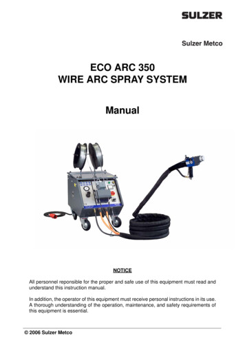
Conclusions are drawn based on theoretical modeling compared to actual test results of low voltagemotor control center arc flash testing.IEEE 1584 9-STEP PROCESS FOR ARC FLASH ANALYSIS [8]Published by the Institute of Electrical and Electronics Engineers and titled "Guide to Performing ArcFlash Calculations," IEEE 1584 provides empirical formulas for determining arcing fault current, flashprotection boundaries, and incident energy. The formulas are valid for systems ranging from 208 V to 15kV. Theoretical formulas are provided for conditions outside this range.ARC FLASH ANALYSIS PROCESSIEEE 1584 establishes a nine-step process for gathering information and calculating arc flash hazards.The steps are:1. COLLECT ELECTRICAL SYSTEM DATACollecting system data is the most difficult and time-intensivestep in performing an arc flash hazard analysis, but accurate information is vital to correctly calculatingflash boundaries. A relatively small error at this point can invalidate all further calculations.Information collected should be recorded on a one-line diagram of the facility's electrical system. Thisdiagram should be updated whenever modifications are made to the system, and a typical diagram isshown in Figure #1.Figure 1: Typical One-Line Diagram
2. DETERMINE MODES OF OPERATIONMany electrical systems, especially in smaller facilities, have only a single mode of operation. In largefacilities, however, it is common to find a number of operating modes, possibly including: emergencymodes in which only backup generators provide power; multiple utility sources or generators that areswitched in or out; and motors or portions of the system that may start or cease operation. All of thesedifferent modes cause changes in current at various points in the system, altering incident energy andflash boundaries.3. DETERMINE BOLTED FAULT CURRENTSThe bolted fault current is the current that would flow through a short circuit consisting of two conductorsbolted together. It is the maximum current available to flow through a short circuit. This information isused to calculate the arc fault currents. Bolted fault currents should be determined for each piece ofequipment likely to require maintenance or inspection while energized.4. DETERMINE ARC FAULT CURRENTSThe current that flows through an arcing fault is usually significantly less than the bolted fault current, dueto greater resistance. Arc fault current calculations are based on voltage, bolted fault current, conductorgap distance, and other factors. IEEE 1584 presents two formulas for calculating arc fault currents, onefor use with 0.208-1 kV systems, and the other for systems between 1 and 15 kV.For systems between 0.208 and 1 kV:lg Ia K 0.662(lg Ibf) 0.0966(V) 0.000526(G) 0.5588(V)(lg Ibf) - 0.00304(G)(lg Ibf)For systems between 1 and 15 kV:lg Ia 0.00402 0.983(lg Ibf)Where Ia arc fault current in kA; K -0.153 for open-air arcs and -0.097 for enclosed arcs; Ibf 3-phasebolted fault current in kA; V voltage in kV; G conductor gap in mm5. DETERMINE PROTECTIVE DEVICE CHARACTERISTICS AND DURATION OF ARCSThe time-current curves of upstream protective devices are a major factor in determining how long an arcfault will last. An effort should be made to determine the actual settings rather than relying on standardvalues, as these may cause incident energy to vary greatly.Another consideration when analyzing protective devices is that incident energy depends on both faultcurrent and time. Since protective devices are slower at lower currents, minimum fault currents often posethe worst-case arc flash scenario.6. DOCUMENT VOLTAGES AND EQUIPMENT CLASSESVoltage and equipment class determine what equationshould be used to find the flash boundary, as well as the bus gap distances required by the equations.Systems operating at 1 kV use a different equation than those operating between 1 kV and 15 kV. In
addition, IEEE 1584 recognizes six equipment classes, as shown in table #1. The bus distances used tohelp determine the arcing fault current.Classes of equipmentTypical bus gaps, mmOpen Air10 – 40Low-voltage switchgear3215kV switchgear1525kV switchgear104Low-voltage MCCs and panelboards25Cable13Table 1: Classification of Equipment with typical bus gaps7. ESTABLISH WORKING DISTANCESThe working distance is the distance from a potential arcsource to a worker’s face and chest. It is a critical quantity in determining the flash hazard boundary, aseven an increase of a few inches in working distance can cause a significant drop in incident energy. 18inches is the working distance most commonly assumed in calculations, but efforts should be made todetermine actual working distances. Some usual working distances are shown in table 2.Classes of equipmentTypical working distance, inLow-voltage switchgear2415kV / 5kV switchgear36Low-voltage MCCs and panelboards18Cable18Table 2: Typical Working Distances.8. DETERMINE INCIDENT ENERGIESIncident energy is defined in NFPA 70E as "the amount of energy impressed on a surface, a certaindistance from the source, generated during an electrical arc event." In an arc flash hazard study, the"surface" is the worker's body at the assumed working distance. Incident energy is expressed in cal/cm2.IEEE 1584 uses the following formulas:(1) E 4.184(Cf)(En)(t/0.2)(610x/Dx)
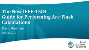
Where E incident energy in joules/cm2; Cf is a calculation factor (1.0 for voltages above 1 kV, and 1.5for voltages below 1 kV); En normalized incident energy (from equation (2) below); t arc duration inseconds; D distance from arc in mm; x distance exponent (see table 3 below)Equipment TypeD (Distance Exponent)Open air2.0Low-voltage (.208-1 kV) switchgear1.473High-voltage (1-15 kV) switchgear0.973Low-voltage MCCs and panels1.641Cables2.0Table 3: Distance Exponent(2) lg En K1 K2 1.081(lg Ia) 0.0011(G)Where En energy normalized for distance of 610 mm and arc duration of 0.2 seconds, in joules/cm2; K1 -0.792 for open-air arcs and -0.555 for enclosed arcs; K2 0 for ungrounded/high-Z systems and 0.113 for grounded systems; G arc gap in mm; Ia predicted 3-phase arc fault current in kA9. DETERMINE FLASH PROTECTION BOUNDARY (FPB)The FPB is the distance at which incident energy is 1.2 cal/cm2, which is the amount of heat needed tocause second-degree burns. [8] The IEEE formula for calculating FPB isDB [4.184(Cf)(En)(t/0.2)(610x/EB)]1/xWhere EB is the desired incident energy at the boundary (usually 1.2 cal/cm2, but occasionally set at avalue matching proposed PPE rating), with other variables defined as for the incident energy equationsabove.ARC FLASH SOFTWARE MODELINGThere is very few credible arc flash software modeling tools available on the market. In order to besuccessful in modeling an arc flash event, three critical items are required. Precise information for everyaspect of the power system with an extensive library of devices to easily add to the model, softwarecompliance to national standards such as IEEE 1584, and expert service available to support anyquestions or enhancement requirements to the model.An arc flash calculation study requires calculating the equivalent arcing short circuit current at eachlocation under study. The arcing current is used to evaluate the time current characteristicof the upstream overcurrent device that would interrupt the arc flash.Electrical network modeling software was used to model the simple circuit for testing the low voltagemotor control center at the lab prior to actual testing. Generator parameters and breaker output
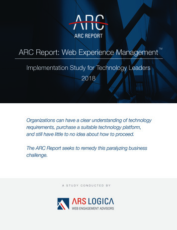
characteristics were provided by the testing power lab, including the bus connection sizing and ampacityrating. This allowed a model to be created as shown in figure 2.Figure 2: Software modeling for arc-flash testingBased on the modeling from software, the electrical system model is graphed comparing incident energy(cal/cm2) with arc flash duration (cycles) [9]. Various characteristics are entered into the model and canhave dramatic changes on the incident energy released as shown in figure 3.350300cal/cm2Incident Energy vsDuration (cycles)25020065 kA 480V BUS150100 kA 480V BUS10065 kA 600V BUS5001351015203050100
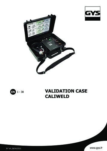
Figure 3: Software modeling analysis results for arc-flash testingOnce the arcing current and clearing time have been established, the IEEE 1584 formulas providemethods to calculate the incident energy in cal/cm2 which can be used for the selection of personalprotective equipment (PPE) as shown in table 4. The incident energy, flash protection boundary andcategory of PPE along with approach limits for shock protection can become part of the detailed arc flashlabel.Min Incident Energy, Max Incident Energy,cal/cm 2cal/cm 2Required Min Ratingof PPE, cal/cm 2Risk Category0Eb*0Eb* 0.0014144.0018288.0012532525.0014044040.001and aboveNot AvailableN/A* Eb is Incident Energy to second degree burn for bare skin exposure.Table 4: Hazard Risk CategoriesAnother important feature of the software shows a comparison of arc duration vs. PPE level required asshown in figure 4. It is clear to see that faster clearing times significantly reduce the PPE requirements.876cal/cm2PPE Level(Above 4 isDANGER)PPE Level vsDuration (cycles)565 kA 480V BUS4100 kA 480V BUS365 kA 600V BUS2101351015203050100Figure 4: PPE level vs. Duration (cycles) – In order to graphically show above Category 4 PPE – this graph maximumvalue is 8 for anything greater than 4.
Once the arc flash study has been completed from your software model, a detailed analysis can beperformed. This analysis includes providing all information for required labels on equipment and shouldprovide a function of printing labels directly from the software as shown in figure 4.Figure 5: Typical Arc flash label required on equipmentAlthough NFPA 70E does not mandate calculations be performed according to the IEEE 1584 methods, itis the method most people use. In addition, a credible software modeling tool can provide valuableinsight into your electrical system performance.ARC FLASH TESTING SETUPArc flash risk factors within a low voltage motor control center or switchgear lineup are generallyassociated with the modular design of the gear. A particular risk concern is the primary connection pointsknown as “stabs” which consists of a moveable breaker or unit - connector that engages a vertical bus inthe section. The connection is made during the removal and plugging in of the bucket at 480/600Vaclevels. The testing comprised of creating an arc flash incident by placing a 10AWG bare copper wireacross the three phases creating a bolted fault condition. Testing parameters for this series of tests weredefined as:1. Voltage – Rated maximum voltage of the equipment – 480V or 600V2. Current ( 5, -0%) Tolerance – Applies for prospective SCCR current – 65kA (68.2 x 65kA).3. (480V@65kA, 480V@100kA and 600V@65kA)a) 600V@65kAb) 480V@100kAc) 480V@65kA4. Peak Current ( 5, -0%) Tolerance – 2.3 Times the values of the internal arcing short-circuitcurrent at 60 Hza) 65kA x 2.3 149.5kA
IEEE Standard 1584 [3], IEEE Guide for Performing Arc Flash Hazard Calculations defines the practice for performing detailed arc flash calculations. This method has become the currently accepted industry practice used for calculating the prospective incident energy that could be available at a given location which can be used to determine the PPE requirements. A software model can be developed .